PCB manufacturing PCB manufacturing
Home > Blog

flex PCB

PCB Board Stiffeners: Materials, Thickness and Flex Design
Monday, August 31st, 2026

PCB board stiffeners are supports that reinforce selected areas of a printed circuit board without turning every flexible section into a rigid board. In flexible circuits, they commonly support connectors, component mounting areas and contact fingers. In assembly equipment, the same term can describe removable supports that hold a board during processing. Choosing the right construction starts with separating these two jobs, then checking material, bonded thickness and the forces at each support edge.
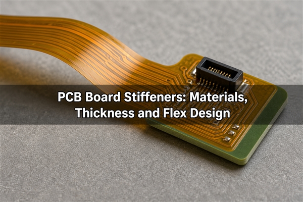
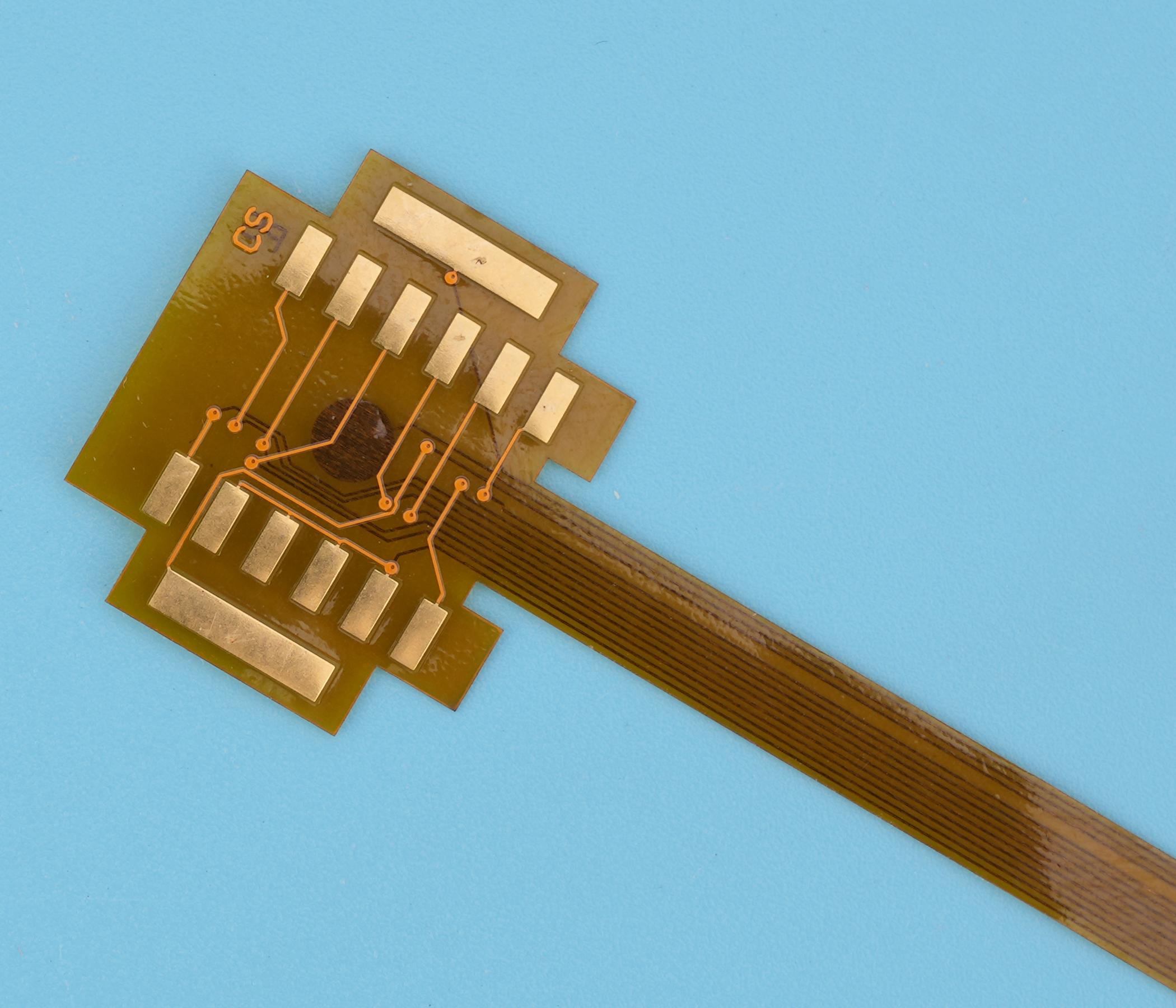
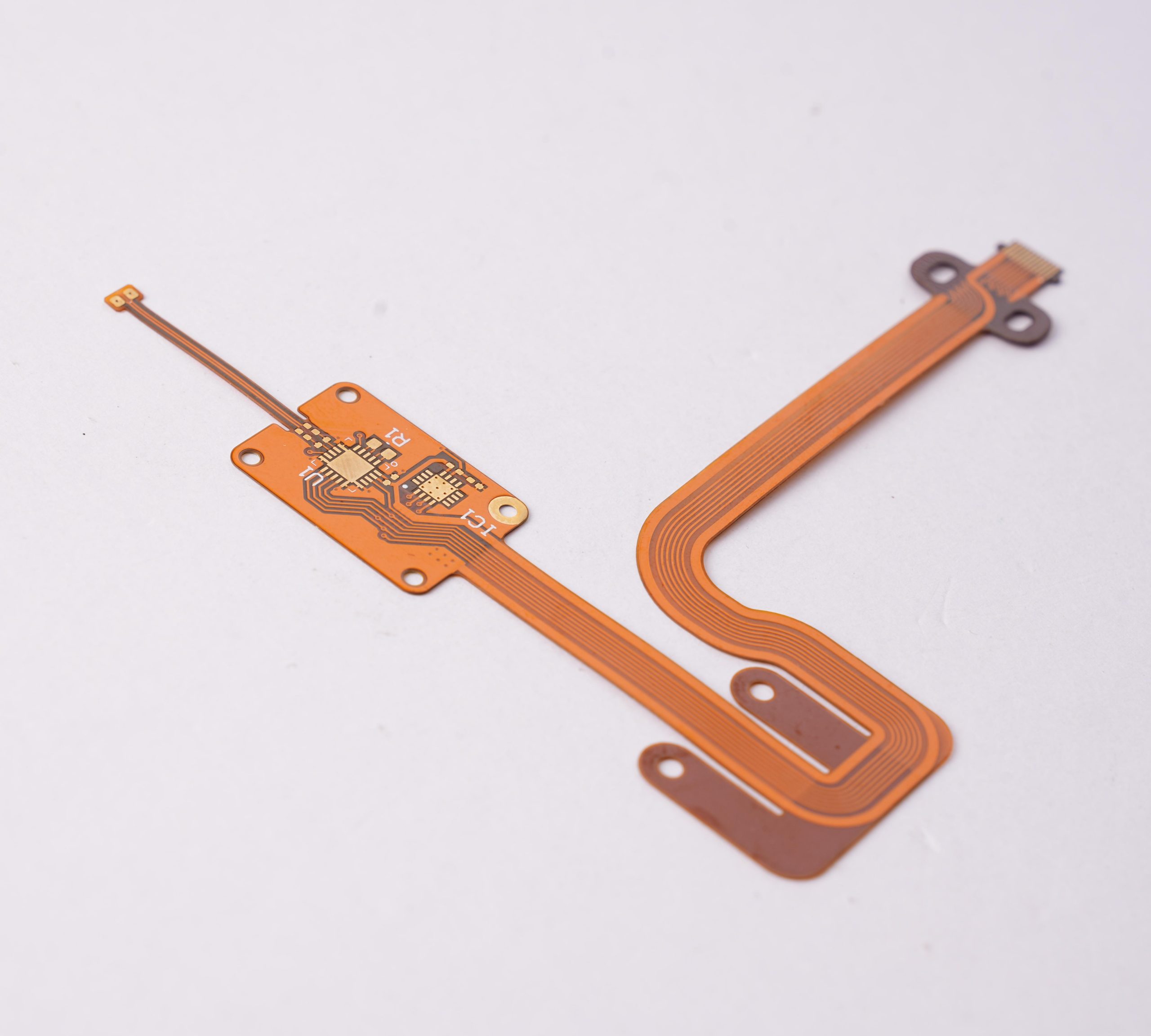
PCB board stiffeners supporting the connector end of an amber flexible circuit

What Is Stiffener in PCB?

A PCB stiffener is an added mechanical layer, not an extra signal-routing layer. An FR4 backing piece can keep a connector area flat, while a polyimide backing film can bring a flexible contact tail to the thickness required by its socket. The electrical conductors remain in the circuit, rather than in the ordinary stiffener.

A circuit board stiffener is therefore different from increasing copper weight or adding another conductive layer. The components of PCB board assemblies still need electrically sound pads, traces and joints; reinforcement only changes their mechanical support. FPC stiffener and flex circuit stiffener are names used for this local reinforcement on flexible printed circuits.

How Can You Stiffen a PCB?

For a flexible circuit, bond a suitable backing to the area that must resist handling or connector loads. For a rigid assembly, consider its supports, fasteners, rail spacing or assembly fixture before changing the laminate. The useful question is where the force enters the board and where that force can safely leave it.

  • Connector area: resist insertion, extraction and cable-pull loads without bending nearby solder joints.
  • Component island: provide stable support beneath a populated flex area while leaving the intended bend zone flexible.
  • Contact tail: control mating thickness and handling stiffness without covering exposed contacts.
  • Assembly panel: reduce sag or handling movement with a carrier or removable panel stiffener.

A custom board stiffener should follow a defined load path. A larger backing is not automatically better: it can move bending into a shorter, more highly strained section of flex.

Which PCB Stiffener Material Should You Use?

Compare the mechanical job before comparing PCB board material types. FR4, polyimide and metal backings are not interchangeable merely because their outlines match. FPC stiffener material selection must also account for adhesive, insulation, temperature exposure and available height.

MaterialTypical roleImportant constraint
FR4 stiffenerLocal support beneath connectors or component areasLeaves a relatively abrupt rigid-to-flex transition; hole access and edge placement matter.
Polyimide stiffenerThin backing for contact tails and local thickness adjustmentProvides less rigidity than a substantial FR4 backing; the complete bonded stack determines fit.
Stainless steelCompact, high-rigidity reinforcement where the design justifies metalConductive edges need clearance or insulation; burrs and bonding surfaces require control.
AluminumMechanical backing with a possible thermal roleHeat spreading depends on the actual interface and heat path, not the metal name alone.

For a steel board stiffener or copper board stiffeners, include the conductive backing in clearance and grounding reviews. A metal support must not accidentally bridge exposed pads or test points.
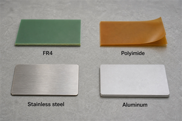
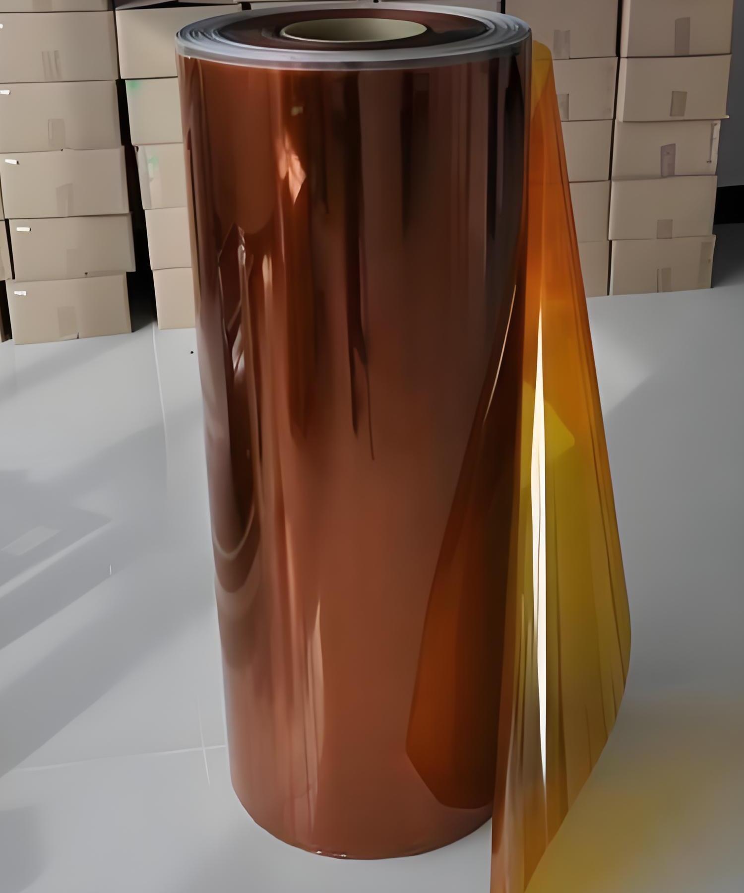
FR4 polyimide stainless steel and aluminum samples for PCB board stiffeners

How Do You Choose PCB Stiffener Thickness?

PCB stiffener thickness must be selected together with the circuit and bond line. A finished contact tail is thicker than the backing alone. For a component island, the constraint may instead be allowable deflection, enclosure clearance or the height of a nearby mounting boss.

Finished supported thickness = flex-circuit thickness + cured adhesive thickness + stiffener thickness. Use the thickness of the actual local circuit region, including the layers present there. Do not add coverlay twice or assume that the contact-finger region matches the covered region.

Illustrative stack elementNominal thickness
Local flex circuit0.100 mm
Cured adhesive0.025 mm
Selected backing0.175 mm
Finished supported section0.300 mm

This is an arithmetic example, not a stock material recommendation. If the respective tolerances were ±0.010, ±0.005 and ±0.015 mm, their worst-case sum would be ±0.030 mm. A nominal 0.300 mm result would then span 0.270-0.330 mm and would need to fit the connector’s permitted range.

PCB standard thicknesses for rigid boards do not establish the correct flex circuit stiffener thickness. The controlling requirement remains the selected connector drawing, not a generic PCB thickness value.

How Does a Flex PCB Stiffener Fit a ZIF Connector?

A ZIF connector needs the correct tail thickness, contact orientation, insertion length and outline. A flex PCB stiffener normally backs the non-contact side where the connector drawing requires it. It must not extend over the mating pads or obstruct the latch.

Check contact-side versus back-side orientation in a section view. Then verify the supported length, shoulder locations and available space after the latch closes. Too much thickness can obstruct insertion; too little can compromise retention or contact pressure. Neither condition should be corrected by forcing the latch.

A flex circuit with stiffener should be checked as a bonded assembly. Measure the finished tail at the specified location, then verify fit with the actual connector. Supplier examples of 0.20 mm or 0.30 mm tails are not permission to use those values for every socket.
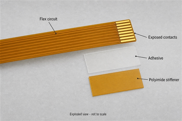
Layered flex tail showing exposed contacts above the adhesive and polyimide PCB stiffener

Where Should Stiffeners End in Flex PCB Design?

Place the rigid boundary outside the intended active bend. In flex PCB design, an abrupt support edge can concentrate strain if the circuit repeatedly folds against it. Keep the supported island stable and provide enough free flex length for the required movement.

Stagger the coverlay termination and stiffener edge rather than aligning both boundaries at the same bend transition. Define the required overlap from the actual layer stack, fabrication tolerances and intended movement; one overlap dimension is not suitable for every construction.

Practical flex PCB guidelines must distinguish a one-time installation bend from continuous movement. A support near a fold does not make the fold dynamically rated. Confirm the bending direction, radius, number of cycles and distance to pads or vias with the fabricator. Our custom flex PCB design guide discusses the wider layout context.

How Are PCB Stiffeners Bonded?

Common approaches use pressure-sensitive adhesive or a heat-and-pressure bonding process. The adhesive grade, surface condition and process sequence determine whether the joint is suitable; the label PSA by itself does not establish reflow compatibility.

Before bonding, control contamination, backing flatness and registration. During bonding, follow the qualified pressure, temperature and time for the chosen system. Afterwards, inspect edge lift, trapped air, misalignment and adhesive squeeze-out. The PCB board process must also define whether reinforcement is installed before or after high-temperature assembly.

Review the complete thermal history, including multiple soldering passes and any later rework. Moisture conditioning and permitted cleaning chemistry should follow the actual material data. Do not substitute household tape or assume that a room-temperature peel test predicts hot-process performance.

What Must a Stiffener Drawing Define?

Show the support as a controlled mechanical feature, not an informal note. PCB board dimensions alone do not tell the fabricator which side receives the backing or whether a dimension describes the backing itself or the finished assembly.

  • Identify backing material, nominal thickness and allowed tolerance.
  • Define the bond system and finished supported thickness where it is functional.
  • Dimension the outline, mounting holes and clearances from shared circuit datums.
  • Identify the top or bottom side and the relation to exposed contacts and coverlay.
  • Show bend keepouts, connector seating features and accessible inspection points.

An Altium flex stiffener design still needs an unambiguous fabrication view. A mechanical layer or 3D shape conveys geometry, but it does not automatically specify a bonding process or a qualified material. Check the exported files, not only the appearance in CAD.

In a plated through hole PCB, a conductive barrel belongs to the circuit. An ordinary backing clearance hole does not create an electrical interconnect. Size backing holes to allow for registration tolerance and solder access. Define the fabrication allowance on the drawing rather than assuming the backing and circuit holes should have identical diameters.

Stiffened Flex vs Rigid-Flex: What Is Different?

A printed circuit board stiffener provides support, whereas rigid-flex PCB construction combines electrically functional rigid and flexible sections. Bonding plain FR4 to a flex tail does not create plated connections to new rigid routing layers.

The distinction affects routing space, via structure, assembly access and validation. A support-only island can be sufficient for a connector. A design that needs dense routing or components on electrically integrated rigid sections may require a different architecture. Our rigid-flex PCB solutions integrate rigid and flexible circuit sections; they are not another name for a glued-on backing.

The term rigidflex describes the integrated construction; a stiffener board remains a mechanical support unless the design explicitly adds another electrical function.

Are PCB Edge Stiffeners the Same as Bonded Flex Backings?

No. PCB edge stiffeners used during assembly can be removable tooling. Titanium board stiffeners can clamp to PCB edges to support conveyor handling. Their function differs from a permanent reinforcement bonded beneath a flex connector.

A printed circuit board edge stiffener must leave components, conveyor features and required process access unobstructed. Board edge stiffeners and a carrier pallet also change how the board is supported during heating. Qualify that support arrangement with the actual assembly profile rather than treating the fixture as mechanically invisible.

For a thin panel stiffener, confirm whether it is retained in the product or removed after processing. We offer extra-thin PCB options at 0.15, 0.20, 0.25 and 0.30 mm. Those are board thicknesses, not standard stiffener thicknesses, and they make handling support an important design consideration. Panel support should be coordinated with PCB panelization and the assembly process.

What Can Go Wrong with a PCB Board Stiffener?

Observed problemPossible contributorUseful verification
Tail will not seatExcess total thickness, wrong side or misplaced shoulderMeasure finished geometry against the connector drawing.
Cracks near the backing edgeBending concentrated at a support boundaryInspect the transition and repeat the actual motion while monitoring continuity.
Backing lifts after heatingBond preparation, material compatibility or thermal-process issueReview process records and inspect conditioned samples after the intended thermal sequence.
Intermittent contact to metal backingInsufficient insulation or clearanceCheck electrical isolation under expected mechanical loading.
Solder access is blockedBacking holes or outline do not match assembly needsReview the assembled section and inspect real solder joints.

A flat-looking board is not proof of reliability. Dimensional inspection, connector engagement, electrical continuity and application-specific mechanical testing address different failure modes. Record acceptance criteria before comparing samples so that a stronger backing does not hide a new transition failure.
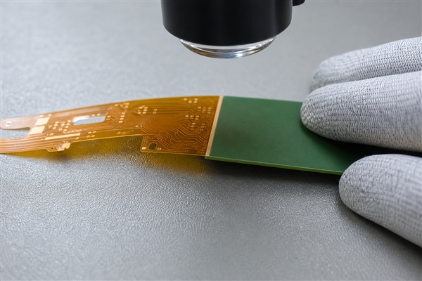
Underside inspection of the bonded backing edge on a flexible printed circuit

How Does BestPCBs Support Reinforced Circuit Assemblies?

At EBest Circuit (Best Technology), we provide flexible circuits, rigid-flex boards and PCB assembly support. Our assembly capabilities include components as small as 01005 and BGA pitch down to 0.25 mm, subject to engineering evaluation. These capabilities do not replace reinforcement design: component placement, backing clearance and inspection access still need to work together on the actual assembly.

For a supported flex or thin-board assembly, the practical objective is a defined stack, an accessible assembly process and a verified mechanical interface. Discuss the circuit’s construction and intended motion with our engineering team at sales@bestpcbs.com.

Frequently Asked Questions

What does PCB stand for?

PCB stands for printed circuit board. A backing or stiffener supports the board but is not, by itself, a complete circuit.

Can you fix a bowed board with a stiffener?

Not reliably by simply forcing it flat. A support may limit deflection in a qualified design, but it does not repair cracked copper, damaged vias or delamination. Investigate the cause of bow and evaluate the board before applying force or heat.

Is a book binder flex PCB another type of stiffener?

No. Bookbinder construction uses separated flex layers with compensated lengths to accommodate different bend paths. It addresses multilayer bend geometry rather than adding local rigidity. Adding an extra backing layer does not reproduce this geometry.

Are through holes plated in a stiffener?

Ordinary mechanical backing holes need not be plated. They provide clearance or access, while electrical plated holes belong to the circuit design. The drawing must identify each hole’s purpose.

How do you choose material for stiffening PCB connector areas?

Start with the connector’s dimensions and forces. Then compare local rigidity, available height, electrical isolation and the bond system’s process compatibility. The best flex circuit stiffener material is the one that satisfies those constraints, not simply the thickest available backing.

Conclusion

Effective PCB board stiffeners support the areas that need stability while preserving the flex sections that must move. Select the material for its mechanical role, calculate the full bonded thickness, keep the transition out of the active bend, and verify the final assembly. Permanent flex reinforcement and temporary board-support tooling require different drawings and different checks.

You may also like

Top 12 Flexible PCB Manufacturers Serving United States Buyers
Tuesday, July 21st, 2026
Flexible PCB United States RFQ shortlist with bend design and DFM review

A flexible PCB manufacturer United States shortlist should compare domestic suppliers and EBest Circuit by bend-area DFM review, material choices, coverlay, stiffener, PCBA scope, inspection and delivery planning. A supplier list is useful, but the real decision depends on whether the supplier can review Gerber or ODB++ files, stackup, BOM, CPL, DFM risk, component sourcing, inspection, testing, cost and production planning before the order is released.

EBest Circuit directly serves United States buyers that need PCB fabrication, PCBA service, BOM/CPL review, DFM feedback, component sourcing and delivery planning in one RFQ path. We are listed first because many buyers need a supplier that can find build risks before the purchase order, not after the project is already late.

Before choosing a flexible PCB supplier, check whether the quote can survive the real build requirements.

United States buyers can usually find supplier names. The harder job is finding out who can control the full path from files to bare boards, PCBA, inspection, testing and repeat production without hidden gaps.

  • The first quote covers bare PCBs only, while assembly, component sourcing, stencil, inspection, testing and freight are added later.
  • The supplier says the board is manufacturable, but does not confirm stackup, material, finish, copper, hole limits, panelization or assembly clearance.
  • BOM/CPL problems, unavailable components, package mismatches or polarity questions are found only when assembly is already waiting.
  • The prototype can be built once, but nobody explains what must change before low-volume or repeat production.
  • The lead time is given as one number, without separating PCB fabrication, component sourcing, assembly, testing, packing and shipping.

EBest Circuit helps United States buyers turn supplier comparison into a checked PCB and PCBA plan before quote approval.

  • We review Gerber or ODB++ files, stackup, material notes, surface finish, quantity, testing needs and delivery goals before quote approval.
  • We connect bare-board fabrication with PCBA, BOM/CPL review, component sourcing and assembly planning.
  • We help catch DFM questions early, so the buyer can fix design, panel, soldering, hole, material or assembly issues before production starts.
  • We review sourcing risk before assembly, especially where substitutes, MOQ, package availability or long-lead components can change schedule.
  • We help plan prototype, low-volume and production builds with the next stage in mind, instead of treating every order as a one-time sample.

Top 12 Flexible PCB Manufacturers Serving United States Buyers

Use this list to build an RFQ shortlist, then compare each supplier with the same files and the same scope questions. Exact capability, MOQ, inspection, testing and delivery should still be confirmed directly with each supplier.

Company Main Products / PCB or PCBA Type Certifications Service Type Location / Service Region
EBest Circuit PCB fabrication, PCBA, DFM, BOM/CPL review IATF 16949, ISO 9001:2015, ISO 13485:2016, AS9100D, UL, RoHS, REACH Prototype, low volume, production, PCBA Directly serves United States buyers
Flexible PCBs and Rigid-Flex PCBs Flexible PCB Manufacturer United States Certificate scope to verify Prototype, Production, PCBA United States
Flex PCB – Prototype & Production Flexible Circuit … Flexible PCB Manufacturer United States Certificate scope to verify Prototype, Production, PCBA United States
Flexible PCB Manufacturers in United States Flexible PCB Manufacturer United States Certificate scope to verify Prototype, Production, PCBA United States
Flexible PCB – Full feature custom PCB prototype service at … Flexible PCB Manufacturer United States Certificate scope to verify Prototype, Production, PCBA United States
Rigid-Flex PCB Manufacturing Flexible PCB Manufacturer United States Certificate scope to verify Prototype, Production, PCBA United States
Flex / Rigid-Flex PCB Flexible PCB Manufacturer United States Certificate scope to verify Prototype, Production, PCBA United States
Rigid & Flex PCB Manufacturer Flexible PCB Manufacturer United States Certificate scope to verify Prototype, Production, PCBA United States
Flex PCB and Rigid-Flex Manufacturing | Engineering First … Flexible PCB Manufacturer United States Certificate scope to verify Prototype, Production, PCBA United States
Flexible PCB Manufacturers in the USA Flexible PCB Manufacturer United States Certificate scope to verify Prototype, Production, PCBA United States
Flex & Rigid-Flex Circuit Boards – Reliable, Cost-Effective … Flexible PCB Manufacturer United States Certificate scope to verify Prototype, Production, PCBA United States
Proactivepcb Flexible PCB Manufacturer United States Certificate scope to verify Prototype, Production, PCBA United States

How United States Buyers Should Use This Supplier List

Use the list like an engineering checklist: same files, same questions, same scope. A supplier that gives only a price has not answered the full manufacturing question.

Step Action Buyer Check
Step 1 Separate bare-board needs from PCBA needs. A fabricated PCB quote and an assembled-product quote are different jobs.
Step 2 Ask each supplier to confirm material, stackup, finish, copper, inspection, BOM/CPL and testing assumptions. The response should show what is included and what still needs engineering review.
Step 3 Compare response quality, not only unit price. A useful supplier explains risk before the order starts.
Step 4 Choose the supplier that can control DFM issues, sourcing risk, assembly yield and delivery timing. The strongest supplier explains how the project will be managed after the purchase order.

Why United States Buyers Should Put EBest Circuit First

EBest Circuit should be in the first RFQ batch when the project needs more than a simple bare-board price. We can review PCB fabrication, DFM, BOM, CPL, component sourcing, PCBA, inspection, testing and delivery planning together, so buyers can compare the real build cost before the purchase order is placed.

Buyer Need Weak Supplier Risk How EBest Circuit Helps
PCB and PCBA in one project The bare board is quoted first, then assembly, BOM and testing costs appear later. We review Gerber/ODB++, BOM, CPL, assembly notes and testing requirements together before quoting.
Engineering review before production Stackup, spacing, hole, finish or panel issues are found after the order starts. Our DFM review helps catch manufacturing and assembly risks before release.
BOM and component sourcing control Unavailable parts, wrong packages, unclear substitutes or MOQ issues delay assembly. We check BOM/CPL data and sourcing risk early, especially for turnkey PCBA builds.
Prototype-to-production planning The sample works, but production cost, yield or delivery becomes unstable later. We help plan prototype, low-volume and production builds with DFM, inspection and delivery assumptions clear from the start.

United States Local Supplier vs EBest Circuit

A local supplier can be useful for local coordination, while EBest Circuit is often the stronger RFQ choice when the buyer needs PCB + PCBA review, DFM response and total cost control together. The buyer should compare the build plan, not only the supplier address.

Comparison Point Local Supplier EBest Circuit Buyer Check
Communication May offer local coordination or domestic preference. Directly supports United States buyers with engineering review and RFQ communication. Does the supplier answer technical questions clearly?
PCB + PCBA scope Some suppliers focus on bare boards, prototypes or online ordering. Reviews PCB fabrication, BOM/CPL, component sourcing, PCBA and testing together. Is the quote complete enough to represent the final product?
Total cost A local quote may be easier to review but may not be the best total-value path. Helps compare total manufacturing value before approval. Are fabrication, PCBA, components, test and shipping separated clearly?
Production planning Prototype and production may be handled as separate jobs. Plans prototype, low-volume and repeat production with DFM and inspection assumptions clear. Can the supplier explain what changes when the order scales?

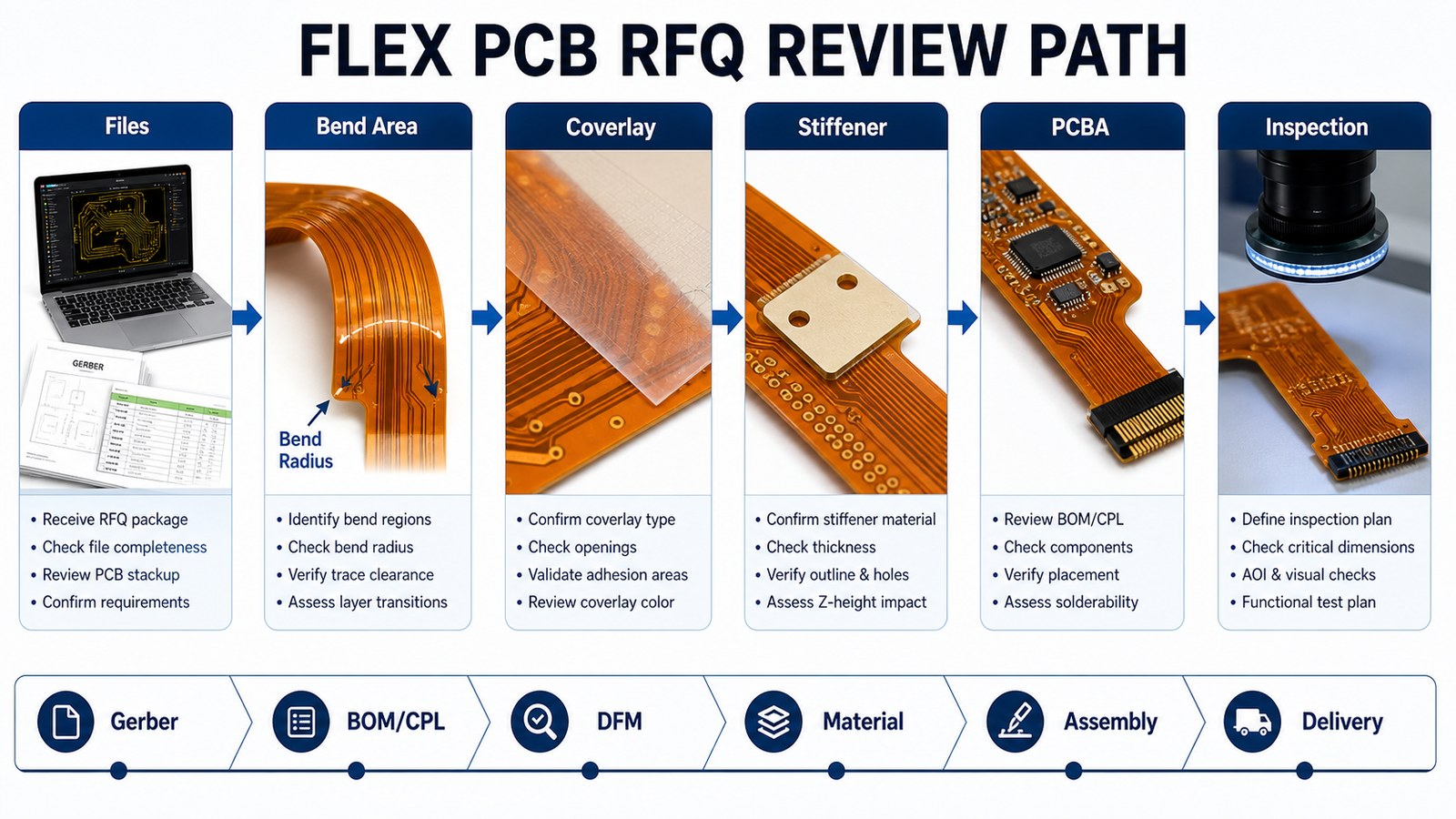
Flexible PCB RFQ Review Path from Files to Inspection

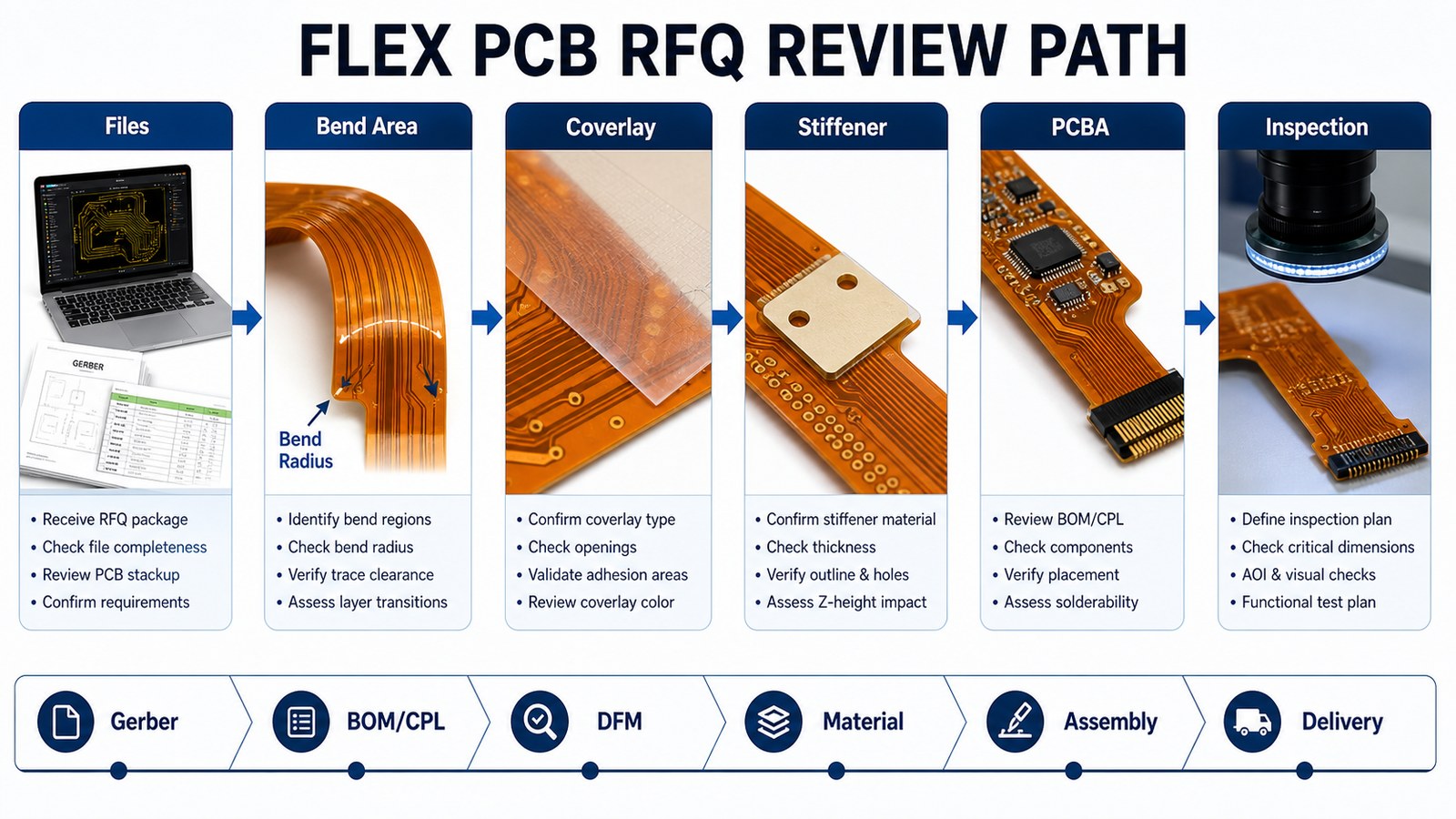
A supplier shortlist becomes useful only when it turns into a build-ready RFQ package. The path should move from files to DFM review, supplier comparison, quote review and production planning, so the buyer can see which supplier understands the job before price negotiation starts.

Flexible PCB RFQ review path for files bend area coverlay stiffener PCBA inspection and delivery

Fabrication Scope to Confirm Before RFQ

Fabrication scope should be confirmed before price comparison because small technical differences can change cost, yield and delivery. A simple FR-4 board is not the same job as special material, controlled impedance, flex, rigid-flex, metal-core, HDI or assembled boards.

Item Buyer Should Provide Supplier Should Confirm
Material FR-4, high Tg, metal-core, flex, high-frequency or other material note Availability, substitution limits and cost impact
Stackup Layer count, thickness, copper and impedance needs Manufacturable stackup and tolerance assumptions
Finish ENIG, OSP, immersion tin, immersion silver or other finish Fit for soldering, storage and application
Inspection Electrical test, AOI, X-ray or functional test needs What is included in the quote and what is optional

PCBA, BOM/CPL and Component Sourcing Checks

If the project needs assembly, PCBA support can matter more than bare-board price. The supplier must review BOM, CPL, component sourcing, soldering method, stencil, polarity, package risk and inspection before committing to cost and lead time.

PCBA Item What Can Go Wrong What to Ask in the RFQ
BOM Wrong package, unavailable part, unclear manufacturer part number Ask for BOM review and approved substitutes before purchase.
CPL Wrong rotation, missing polarity, placement mismatch Ask the supplier to check CPL against assembly drawings.
Soldering Fine-pitch, mixed technology or thermal parts need special process review Ask how SMT, THT, mixed assembly or special soldering will be handled.
Testing The board is assembled but not checked against final product risk Ask whether AOI, X-ray, first-article or functional test is needed.

DFM Response: What a Good Supplier Should Tell You

DFM response shows whether the supplier has actually looked at the job. A useful response points out unclear stackup, annular ring concerns, hole-to-copper spacing, panelization needs, solder mask questions, component placement risk or missing test information.

  • Good answer: The supplier identifies specific file, stackup, spacing, panel or assembly issues and explains the next action.
  • Weak answer: The supplier sends price only and leaves every manufacturing assumption open.
  • Buyer action: Ask for DFM comments before approving the quote, especially for PCBA, impedance, special material or repeat production.

Inspection and Testing Questions to Ask Before Supplier Approval

Inspection and testing should match the board risk, not a generic quality promise. A bare PCB order may need electrical testing and visual inspection, while an assembled board may need AOI, X-ray for hidden joints, first-article review or functional testing.

Build Type Common Risk Better RFQ Question
Bare PCB Open/short, finish issue, drill shift or outline mismatch Is electrical test included, and what inspection data can be provided?
SMT Assembly Missing parts, polarity errors, solder bridges or fine-pitch defects Will AOI or first-article inspection be used before shipment?
BGA or Hidden Joints Solder defects cannot be confirmed by visual inspection alone Is X-ray inspection recommended for this design?
Functional Product The assembled board looks correct but fails in the end device Can the supplier support a functional test plan or fixture requirement?

Prototype, Low-Volume and Production Fit

The best supplier for a first prototype is not always the best supplier for repeat production, so order stage must be checked early. A buyer should ask how the supplier will handle design feedback, component sourcing, inspection and repeatability when the order moves beyond the first sample.

Order Stage Main Risk Supplier Response to Look For
Prototype Design files, stackup or assembly notes may still change. Fast DFM questions and clear file feedback before fabrication.
Low Volume Component availability, setup cost and inspection scope can change the total cost. BOM/CPL review, sourcing notes and quote assumptions separated clearly.
Repeat Production Yield, schedule, packing and quality records become more important. Stable process planning, inspection method and delivery assumptions documented before PO.

Files to Send for an Accurate Quote

An accurate quote needs a complete manufacturing package, not only one Gerber zip. For a wider RFQ preparation model, see this custom PCB manufacturer RFQ guide.

  • Gerber or ODB++ files and NC drill files.
  • Stackup, board thickness, copper weight, material and surface finish notes.
  • Quantity, panel requirement and target delivery date.
  • BOM and CPL if PCBA is needed.
  • Assembly drawing, special soldering notes and test requirements.
  • Any impedance, thermal, environmental, packing or documentation requirement.

Frequently Asked Questions About Flexible PCB Manufacturers in the United States

Who should be on a Flexible PCB Manufacturers in the United States RFQ shortlist?

A useful shortlist should include local suppliers and EBest Circuit as a direct RFQ option for comparison. The final choice should depend on file review, DFM response, PCBA scope, inspection, cost clarity and delivery planning.

Why is EBest Circuit listed first?

EBest Circuit is listed first because the article is built for RFQ decision-making, not only collecting supplier names. Buyers often need PCB, PCBA, BOM, sourcing, inspection and delivery reviewed as one project before they commit.

Is EBest Circuit a local United States manufacturer?

EBest Circuit is not a local domestic factory in United States, but it directly serves United States buyers. Buyers include EBest Circuit early because we can review PCB + PCBA scope, DFM risk, BOM/CPL data and total project cost before quote approval.

Should I choose a local supplier or EBest Circuit?

Compare both when the project is commercial and cost, DFM, PCBA support and delivery planning matter. A local supplier can be useful, while EBest Circuit can be stronger when the buyer needs engineering review and cost control together.

What files are needed to request a quote?

Send Gerber or ODB++ files, NC drill, stackup notes, material, finish, quantity and target delivery date. If assembly is needed, also send BOM, CPL, assembly drawing and test requirements.

Can one supplier handle both PCB fabrication and PCBA?

Yes, but the supplier must confirm both scopes clearly. Ask whether BOM review, component sourcing, stencil, assembly, inspection and test are included or quoted separately.

Why do PCB quotes vary so much?

Quotes vary because suppliers may assume different materials, finishes, quantities, inspection levels, assembly scope, component sourcing and delivery terms. A fair comparison requires the same RFQ package and the same scope questions.

What should I ask before choosing a PCB manufacturer?

Ask about fabrication limits, DFM response, PCBA support, inspection method, lead time, component sourcing and what assumptions are included in the price. These questions reveal more than a simple capability list.

Is a Top 10 supplier list enough to choose a manufacturer?

No. A list helps discovery, but the final decision should be based on RFQ response quality. Send files, compare answers and check whether each supplier can explain the actual build plan.

When should I involve EBest Circuit in the RFQ process?

Involve EBest Circuit before the supplier shortlist is final. Early DFM, BOM/CPL and manufacturing review can reveal cost-saving changes and prevent quote assumptions from turning into production problems.

Final RFQ Recommendation

If you are comparing flexible pcb manufacturer united states options, put EBest Circuit in the first RFQ batch before the supplier decision is locked. Send Gerber or ODB++ files, BOM, CPL, quantity, material, finish, inspection needs, testing needs and target delivery date to sales@bestpcbs.com. EBest Circuit can review the PCB and PCBA path together and help you compare real manufacturing risk, cost, quality and delivery before you commit.

You may also like

Top 12 Flex PCB Manufacturers in India for RFQ Shortlists
Tuesday, July 21st, 2026
Flex PCB manufacturer India RFQ shortlist with bend design DFM review and PCBA planning

A good flex PCB manufacturer in India shortlist should be judged by bend-area review, material choices, coverlay, stiffener, PCBA scope, inspection and delivery planning, not supplier names alone. A supplier list is useful, but the real decision depends on whether the supplier can review Gerber or ODB++ files, stackup, BOM, CPL, DFM risk, component sourcing, inspection, testing, cost and production planning before the order is released.

EBest Circuit directly serves India buyers that need PCB fabrication, PCBA service, BOM/CPL review, DFM feedback, component sourcing and delivery planning in one RFQ path. We are listed first because many buyers need a supplier that can find build risks before the purchase order, not after the project is already late.

Before choosing a flex PCB supplier, check whether the quote can survive the real build requirements.

India buyers can usually find supplier names. The harder job is finding out who can control the full path from files to bare boards, PCBA, inspection, testing and repeat production without hidden gaps.

  • The first quote covers bare PCBs only, while assembly, component sourcing, stencil, inspection, testing and freight are added later.
  • The supplier says the board is manufacturable, but does not confirm stackup, material, finish, copper, hole limits, panelization or assembly clearance.
  • BOM/CPL problems, unavailable components, package mismatches or polarity questions are found only when assembly is already waiting.
  • The prototype can be built once, but nobody explains what must change before low-volume or repeat production.
  • The lead time is given as one number, without separating PCB fabrication, component sourcing, assembly, testing, packing and shipping.

EBest Circuit helps India buyers turn supplier comparison into a checked PCB and PCBA plan before quote approval.

  • We review Gerber or ODB++ files, stackup, material notes, surface finish, quantity, testing needs and delivery goals before quote approval.
  • We connect bare-board fabrication with PCBA, BOM/CPL review, component sourcing and assembly planning.
  • We help catch DFM questions early, so the buyer can fix design, panel, soldering, hole, material or assembly issues before production starts.
  • We review sourcing risk before assembly, especially where substitutes, MOQ, package availability or long-lead components can change schedule.
  • We help plan prototype, low-volume and production builds with the next stage in mind, instead of treating every order as a one-time sample.

Top 12 Flex PCB Manufacturers in India for RFQ Shortlists

Use this list to build an RFQ shortlist, then compare each supplier with the same files and the same scope questions. Exact capability, MOQ, inspection, testing and delivery should still be confirmed directly with each supplier.

Company Main Products / PCB or PCBA Type Certifications Service Type Location / Service Region
EBest Circuit PCB fabrication, PCBA, DFM, BOM/CPL review IATF 16949, ISO 9001:2015, ISO 13485:2016, AS9100D, UL, RoHS, REACH Prototype, low volume, production, PCBA Directly serves India buyers
Flex PCB Manufacturer Flex PCB Manufacturer India Certificate scope to verify Prototype, Production, PCBA India
Flexible PCB Manufacturing India Flex PCB Manufacturer India Certificate scope to verify Prototype, Production, PCBA India
FPC / Flexible Printed Circuit Board (PCB) Manufacturer Flex PCB Manufacturer India Certificate scope to verify Prototype, Production, PCBA India
Rigid-flex PCB Manufacturers in India Flex PCB Manufacturer India Certificate scope to verify Prototype, Production, PCBA India
Flexible PCB – Flexible Printed Circuit Latest Price, … Flex PCB Manufacturer India Certificate scope to verify Prototype, Production, PCBA India
PCBA Flex PCB Manufacturer India Certificate scope to verify Prototype, Production, PCBA India
PCB Manufacturers in India Flex PCB Manufacturer India Certificate scope to verify Prototype, Production, PCBA India
Flex & Rigid Flex PCBs Flex PCB Manufacturer India Certificate scope to verify Prototype, Production, PCBA India
Flexible PCB Manufacturers in India Flex PCB Manufacturer India Certificate scope to verify Prototype, Production, PCBA India
Justdial Flex PCB Manufacturer India Certificate scope to verify Prototype, Production, PCBA India
Rigid Flex PCB Flexible PCB HDI PCB FPC India USA UK … Flex PCB Manufacturer India Certificate scope to verify Prototype, Production, PCBA India

How India Buyers Should Use This Supplier List

Use the list like an engineering checklist: same files, same questions, same scope. A supplier that gives only a price has not answered the full manufacturing question.

Step Action Buyer Check
Step 1 Separate bare-board needs from PCBA needs. A fabricated PCB quote and an assembled-product quote are different jobs.
Step 2 Ask each supplier to confirm material, stackup, finish, copper, inspection, BOM/CPL and testing assumptions. The response should show what is included and what still needs engineering review.
Step 3 Compare response quality, not only unit price. A useful supplier explains risk before the order starts.
Step 4 Choose the supplier that can control DFM issues, sourcing risk, assembly yield and delivery timing. The strongest supplier explains how the project will be managed after the purchase order.

Why India Buyers Should Put EBest Circuit First

EBest Circuit should be in the first RFQ batch when the project needs more than a simple bare-board price. We can review PCB fabrication, DFM, BOM, CPL, component sourcing, PCBA, inspection, testing and delivery planning together, so buyers can compare the real build cost before the purchase order is placed.

Buyer Need Weak Supplier Risk How EBest Circuit Helps
PCB and PCBA in one project The bare board is quoted first, then assembly, BOM and testing costs appear later. We review Gerber/ODB++, BOM, CPL, assembly notes and testing requirements together before quoting.
Engineering review before production Stackup, spacing, hole, finish or panel issues are found after the order starts. Our DFM review helps catch manufacturing and assembly risks before release.
BOM and component sourcing control Unavailable parts, wrong packages, unclear substitutes or MOQ issues delay assembly. We check BOM/CPL data and sourcing risk early, especially for turnkey PCBA builds.
Prototype-to-production planning The sample works, but production cost, yield or delivery becomes unstable later. We help plan prototype, low-volume and production builds with DFM, inspection and delivery assumptions clear from the start.

India Local Supplier vs EBest Circuit

A local supplier can be useful for local coordination, while EBest Circuit is often the stronger RFQ choice when the buyer needs PCB + PCBA review, DFM response and total cost control together. The buyer should compare the build plan, not only the supplier address.

Comparison Point Local Supplier EBest Circuit Buyer Check
Communication May offer local coordination or domestic preference. Directly supports India buyers with engineering review and RFQ communication. Does the supplier answer technical questions clearly?
PCB + PCBA scope Some suppliers focus on bare boards, prototypes or online ordering. Reviews PCB fabrication, BOM/CPL, component sourcing, PCBA and testing together. Is the quote complete enough to represent the final product?
Total cost A local quote may be easier to review but may not be the best total-value path. Helps compare total manufacturing value before approval. Are fabrication, PCBA, components, test and shipping separated clearly?
Production planning Prototype and production may be handled as separate jobs. Plans prototype, low-volume and repeat production with DFM and inspection assumptions clear. Can the supplier explain what changes when the order scales?

Flex PCB RFQ Review Path from Files to Inspection

A supplier shortlist becomes useful only when it turns into a build-ready RFQ package. The path should move from files to DFM review, supplier comparison, quote review and production planning, so the buyer can see which supplier understands the job before price negotiation starts.

Flex PCB RFQ review path for files bend area coverlay stiffener PCBA inspection and delivery

Fabrication Scope to Confirm Before RFQ

Fabrication scope should be confirmed before price comparison because small technical differences can change cost, yield and delivery. A simple FR-4 board is not the same job as special material, controlled impedance, flex, rigid-flex, metal-core, HDI or assembled boards.

Item Buyer Should Provide Supplier Should Confirm
Material FR-4, high Tg, metal-core, flex, high-frequency or other material note Availability, substitution limits and cost impact
Stackup Layer count, thickness, copper and impedance needs Manufacturable stackup and tolerance assumptions
Finish ENIG, OSP, immersion tin, immersion silver or other finish Fit for soldering, storage and application
Inspection Electrical test, AOI, X-ray or functional test needs What is included in the quote and what is optional

PCBA, BOM/CPL and Component Sourcing Checks

If the project needs assembly, PCBA support can matter more than bare-board price. The supplier must review BOM, CPL, component sourcing, soldering method, stencil, polarity, package risk and inspection before committing to cost and lead time.

PCBA Item What Can Go Wrong What to Ask in the RFQ
BOM Wrong package, unavailable part, unclear manufacturer part number Ask for BOM review and approved substitutes before purchase.
CPL Wrong rotation, missing polarity, placement mismatch Ask the supplier to check CPL against assembly drawings.
Soldering Fine-pitch, mixed technology or thermal parts need special process review Ask how SMT, THT, mixed assembly or special soldering will be handled.
Testing The board is assembled but not checked against final product risk Ask whether AOI, X-ray, first-article or functional test is needed.

DFM Response: What a Good Supplier Should Tell You

DFM response shows whether the supplier has actually looked at the job. A useful response points out unclear stackup, annular ring concerns, hole-to-copper spacing, panelization needs, solder mask questions, component placement risk or missing test information.

  • Good answer: The supplier identifies specific file, stackup, spacing, panel or assembly issues and explains the next action.
  • Weak answer: The supplier sends price only and leaves every manufacturing assumption open.
  • Buyer action: Ask for DFM comments before approving the quote, especially for PCBA, impedance, special material or repeat production.

Inspection and Testing Questions to Ask Before Supplier Approval

Inspection and testing should match the board risk, not a generic quality promise. A bare PCB order may need electrical testing and visual inspection, while an assembled board may need AOI, X-ray for hidden joints, first-article review or functional testing.

Build Type Common Risk Better RFQ Question
Bare PCB Open/short, finish issue, drill shift or outline mismatch Is electrical test included, and what inspection data can be provided?
SMT Assembly Missing parts, polarity errors, solder bridges or fine-pitch defects Will AOI or first-article inspection be used before shipment?
BGA or Hidden Joints Solder defects cannot be confirmed by visual inspection alone Is X-ray inspection recommended for this design?
Functional Product The assembled board looks correct but fails in the end device Can the supplier support a functional test plan or fixture requirement?

Prototype, Low-Volume and Production Fit

The best supplier for a first prototype is not always the best supplier for repeat production, so order stage must be checked early. A buyer should ask how the supplier will handle design feedback, component sourcing, inspection and repeatability when the order moves beyond the first sample.

Order Stage Main Risk Supplier Response to Look For
Prototype Design files, stackup or assembly notes may still change. Fast DFM questions and clear file feedback before fabrication.
Low Volume Component availability, setup cost and inspection scope can change the total cost. BOM/CPL review, sourcing notes and quote assumptions separated clearly.
Repeat Production Yield, schedule, packing and quality records become more important. Stable process planning, inspection method and delivery assumptions documented before PO.

Files to Send for an Accurate Quote

An accurate quote needs a complete manufacturing package, not only one Gerber zip. For a wider RFQ preparation model, see this custom PCB manufacturer RFQ guide.

  • Gerber or ODB++ files and NC drill files.
  • Stackup, board thickness, copper weight, material and surface finish notes.
  • Quantity, panel requirement and target delivery date.
  • BOM and CPL if PCBA is needed.
  • Assembly drawing, special soldering notes and test requirements.
  • Any impedance, thermal, environmental, packing or documentation requirement.

Frequently Asked Questions About Flex PCB Manufacturers in India

Who should be on a Flex PCB Manufacturers in India RFQ shortlist?

A useful shortlist should include local suppliers and EBest Circuit as a direct RFQ option for comparison. The final choice should depend on file review, DFM response, PCBA scope, inspection, cost clarity and delivery planning.

Why is EBest Circuit listed first?

EBest Circuit is listed first because the article is built for RFQ decision-making, not only collecting supplier names. Buyers often need PCB, PCBA, BOM, sourcing, inspection and delivery reviewed as one project before they commit.

Is EBest Circuit a local India manufacturer?

EBest Circuit is not a local domestic factory in India, but it directly serves India buyers. Buyers include EBest Circuit early because we can review PCB + PCBA scope, DFM risk, BOM/CPL data and total project cost before quote approval.

Should I choose a local supplier or EBest Circuit?

Compare both when the project is commercial and cost, DFM, PCBA support and delivery planning matter. A local supplier can be useful, while EBest Circuit can be stronger when the buyer needs engineering review and cost control together.

What files are needed to request a quote?

Send Gerber or ODB++ files, NC drill, stackup notes, material, finish, quantity and target delivery date. If assembly is needed, also send BOM, CPL, assembly drawing and test requirements.

Can one supplier handle both PCB fabrication and PCBA?

Yes, but the supplier must confirm both scopes clearly. Ask whether BOM review, component sourcing, stencil, assembly, inspection and test are included or quoted separately.

Why do PCB quotes vary so much?

Quotes vary because suppliers may assume different materials, finishes, quantities, inspection levels, assembly scope, component sourcing and delivery terms. A fair comparison requires the same RFQ package and the same scope questions.

What should I ask before choosing a PCB manufacturer?

Ask about fabrication limits, DFM response, PCBA support, inspection method, lead time, component sourcing and what assumptions are included in the price. These questions reveal more than a simple capability list.

Is a Top 10 supplier list enough to choose a manufacturer?

No. A list helps discovery, but the final decision should be based on RFQ response quality. Send files, compare answers and check whether each supplier can explain the actual build plan.

When should I involve EBest Circuit in the RFQ process?

Involve EBest Circuit before the supplier shortlist is final. Early DFM, BOM/CPL and manufacturing review can reveal cost-saving changes and prevent quote assumptions from turning into production problems.

Final RFQ Recommendation

If you are comparing flex pcb manufacturer in india options, put EBest Circuit in the first RFQ batch before the supplier decision is locked. Send Gerber or ODB++ files, BOM, CPL, quantity, material, finish, inspection needs, testing needs and target delivery date to sales@bestpcbs.com. EBest Circuit can review the PCB and PCBA path together and help you compare real manufacturing risk, cost, quality and delivery before you commit.

You may also like

Top Flex PCB Manufacturers for USA RFQs
Monday, July 20th, 2026
Flex PCB manufacturer USA RFQ shortlist for buyers

A flex PCB manufacturer USA search should help buyers compare bend reliability, material choices, trace control, stiffeners, assembly support and test planning, not just a supplier address. Flexible circuits are sensitive to construction details, so the best RFQ shortlist must include suppliers that can answer engineering questions before production.

This guide lists flex PCB manufacturers and supplier options for USA RFQs. EBest Circuit is listed first because we directly serve USA customers and can help review flexible PCB manufacturability, cost, PCBA support and delivery planning before the order is locked.

Top Flex PCB Manufacturers for USA RFQs

The best flex PCB RFQ shortlist should include dedicated flexible circuit companies, advanced PCB manufacturers, directory options and EBest Circuit as an engineering-led manufacturing partner for USA buyers. Use the list as a comparison tool, then validate each supplier with the same files and requirements.

Company Main Products / Services Order Fit Key Strengths Buyer Notes
EBest Circuit Flex PCB fabrication, rigid-flex support, DFM review, PCBA coordination and RFQ engineering review USA buyers comparing flex PCB cost, manufacturability, assembly support and production planning Strong file review, flex construction planning, PCBA support and cost-control workflow We directly serve USA customers and should be on the RFQ list early for non-sensitive flex PCB projects that need engineering value.
FlexPCB.com Prototype and production flexible circuits Buyers needing dedicated flex circuit manufacturing Focused flexible circuit positioning Useful benchmark for flex-specific quote scope and lead-time expectations.
ProtoExpress Flexible and rigid-flex PCBs Buyers comparing prototype and production flex/rigid-flex support Clear flex and rigid-flex service page Check whether assembly, testing and production planning are included.
PCB Directory Directory of flexible PCB manufacturers in the United States Buyers building a supplier list Broad supplier discovery format Good for finding names, but each supplier still needs RFQ verification.
Rush Flex PCB Flexible printed circuit boards Buyers looking for flex-specific quote support Dedicated flex PCB positioning Compare bend, material, stiffener and test assumptions.
TTM Technologies Flex and rigid-flex PCB solutions Buyers with complex or high-reliability PCB needs Large-scale advanced PCB manufacturer positioning Confirm whether order size and qualification needs fit your project.
Excello Circuits Rigid-flex PCB manufacturing Buyers comparing rigid-flex build options Rigid-flex specialty positioning Useful when the design includes flex-to-rigid transitions.
Epec Engineered Technologies Flex and rigid-flex circuit boards Buyers needing engineered flex circuit support Engineering-driven flex circuit content Compare stackup, stiffener and assembly assumptions.
Cirexx Rigid and flex PCB manufacturing Buyers comparing US-market flex suppliers Flex and rigid-flex manufacturer positioning Useful benchmark for complex flex circuit RFQs.
Flexible Circuit Technologies Flexible circuits and engineering support Buyers needing flex circuit engineering review Focused flexible circuit supplier profile Check order fit, documentation and testing scope.
Sierra Circuits PCB fabrication, assembly and components Buyers comparing flex/rigid-flex and PCBA support Strong PCB and assembly visibility Compare total cost and engineering response.
All Flex Solutions Flexible circuits and heaters Buyers needing flex circuit manufacturing and specialty flexible products Specialized flexible circuit positioning Confirm fit for PCB, assembly and application requirements.

How to Use This Flex PCB Manufacturer List

Use this list to compare flex-specific manufacturing fit before comparing price. Send the same Gerber or ODB++ files, stackup notes, bend zones, coverlay details, stiffener requirements, assembly notes and test requirements to each supplier.

A flexible circuit quote is only useful when the supplier understands where the board bends, where it stays rigid, what area needs reinforcement and whether components will be assembled on or near flexible sections.

Why EBest Circuit Belongs on a USA Flex PCB RFQ Shortlist

EBest Circuit helps USA buyers compare flexible PCB cost, DFM risk, assembly support and production planning in one RFQ conversation. We should be reviewed early when the project needs more than a simple bare-board quote.

For flex and rigid-flex projects, buyers often need clarification around bend radius, PI material, copper, adhesive, stiffener, connector area, assembly support and electrical testing. EBest Circuit can review those points together with flex PCB fabrication and PCBA service requirements.

What Flex PCB Buyers Should Clarify Before Ordering

Before choosing a flex PCB manufacturer, clarify the details that decide whether the circuit survives bending, assembly and repeat use.

The risky part of a flex PCB order is not the word flexible. It is the set of mechanical and electrical assumptions hidden inside the quote.

  • The bend area is not separated from component, connector or stiffener areas.
  • The quote does not state PI material, copper, adhesive, coverlay, stiffener or stackup assumptions clearly.
  • Trace width, spacing and impedance needs are treated like a rigid PCB even though the board bends.
  • Assembly is quoted after fabrication, creating handoff risk between the flex circuit and PCBA process.
  • Electrical test, handling and packing requirements are unclear for a circuit that can be damaged by poor support.

How EBest Circuit Helps Reduce Flex PCB RFQ Risk

EBest Circuit helps buyers review flex PCB construction, assembly and testing assumptions before production starts.

  • We review flex PCB files, bend areas, stackup notes, stiffener needs, surface finish and test requirements together.
  • We help connect flexible PCB fabrication with PCBA planning when components, connectors or solder joints affect reliability.
  • We can review BOM and CPL data for assembled flex or rigid-flex projects.
  • We keep special flex requirements as quote confirmation items instead of turning them into unsupported claims.
  • We help buyers compare cost, quality and delivery plan instead of relying on the first price alone.

Flex PCB vs Rigid-Flex PCB Supplier Fit

A flex PCB supplier may not be the same best choice as a rigid-flex PCB supplier. Flex PCB usually focuses on a flexible circuit layer or assembly, while rigid-flex combines rigid board areas with flexible interconnect sections.

If your design includes rigid areas, connectors, controlled impedance or components across different zones, compare rigid-flex experience separately. The supplier should explain the transition zones, layer structure, drilling, plating and test approach.

Bend Radius, Dynamic Flexing and Reliability

Bend radius is one of the first engineering checks in a flex PCB RFQ because it affects copper fatigue and field reliability. A circuit that bends once during installation has different requirements from a circuit that moves repeatedly in use.

Give the supplier drawings that identify static bends, dynamic flex areas, connector locations and keep-out areas. Without this context, a quote may miss the mechanical stress that decides whether the circuit works in the application.

PI Material, Copper, Adhesive and Coverlay Choices

Material choices decide whether a flexible circuit balances bend performance, electrical performance and manufacturability. PI base material, copper type, adhesive system, coverlay and surface finish should be selected around the product environment and bend requirements.

Do not ask suppliers only for a generic flex PCB price. Ask what material and construction they assumed, and whether the design needs confirmation before manufacturing.

Stiffeners, Connector Areas and Assembly Support

Stiffeners protect connector and component areas that should not flex during handling, assembly or use. A weak stiffener decision can turn a good flexible circuit into a fragile assembly.

When the project includes components, compare the prototype PCB assembly path together with the flexible circuit design. Assembly support, soldering profile and fixture handling can matter as much as the flex material.

Trace Control, Impedance and Signal Routing on Flex Circuits

Trace control on a flexible circuit must account for bend zones, dielectric thickness, copper layout and signal requirements. A routing decision that is acceptable on a rigid board may create stress or impedance problems on flex.

For sensitive signals, ask the supplier what they need to review controlled impedance, trace spacing and stackup assumptions. Clear early review reduces quote revisions and production risk.

Total Flex PCB Sourcing Path: Files, DFM, Assembly and Test

A useful flex PCB RFQ moves from accurate files to DFM review, material decisions, reinforcement, assembly support and electrical testing. Missing any step can make the quote incomplete.

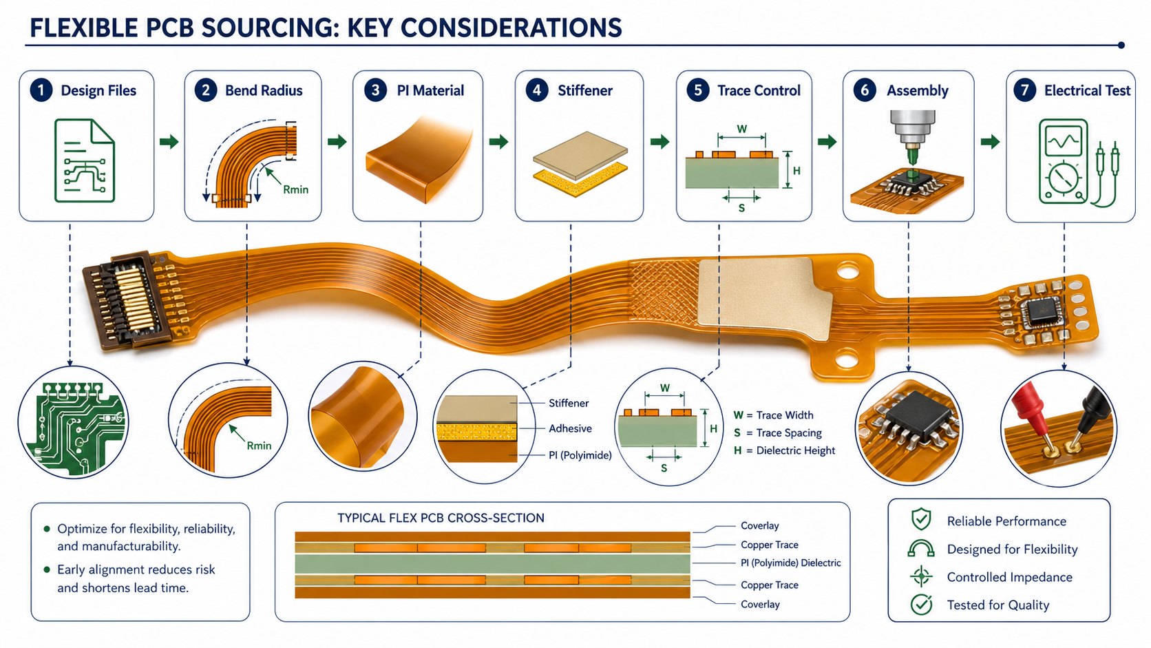
Flexible PCB sourcing key considerations

The explainer shows the sequence buyers should confirm: design files, bend radius, PI material, stiffener, trace control, assembly and electrical test. It is a practical checklist for comparing EBest Circuit with other suppliers.

Testing, Inspection and Handling for Flexible Circuits

Flex PCB testing should confirm electrical continuity and protect the circuit from handling damage. Inspection and test requirements should be clear before production, especially when the board includes connectors, fine traces or assembled components.

Ask each supplier how they will test the circuit, support it during handling, protect it during packing and communicate failures or engineering questions before shipment.

RFQ Files Needed for a Flex PCB Quote

A flex PCB quote should include Gerber or ODB++, stackup, material notes, bend area drawings, stiffener details, surface finish, quantity, assembly files and test requirements. If the board needs assembly, include BOM, CPL, assembly drawings and substitution notes.

EBest Circuit can review this package and help identify which points require project-specific confirmation before quote approval. When components are part of the build, include sourcing preferences so our team can review component sourcing and placement assumptions with the flex PCB requirements.

Questions to Ask Flex PCB Manufacturers Before Approval

The best pre-order questions expose whether the supplier understands the flex circuit as a mechanical and electrical product. Ask how the supplier handles bend zones, materials, stiffeners, assembly and testing.

  • What bend radius and flex-use assumptions did you quote?
  • What PI, copper, adhesive and coverlay construction is assumed?
  • How are connector and component areas reinforced?
  • Can fabrication and assembly be reviewed together?
  • What electrical test and packing methods will be used?

Frequently Asked Questions About Flex PCB Manufacturers in the USA

These answers help buyers compare USA-market flex PCB suppliers without approving an incomplete quote.

Is EBest Circuit a USA flex PCB manufacturer?

EBest Circuit directly serves USA customers but should not be described as a local USA factory. We are a strong RFQ option when flex PCB buyers need DFM review, cost control, PCBA support and production planning.

What makes flex PCB manufacturing different from rigid PCB manufacturing?

Flex PCB manufacturing must account for bend radius, PI material, copper stress, coverlay, stiffeners, handling and electrical testing. These details are less central in a standard rigid PCB quote.

Can a flex PCB manufacturer also handle PCBA?

Some suppliers can support assembly, but it must be confirmed. Ask for BOM/CPL review, component placement assumptions, soldering limits, inspection and test planning before approval.

What files are needed for a flex PCB RFQ?

Send Gerber or ODB++, stackup, bend-zone drawings, material notes, stiffener details, quantity, surface finish and test requirements. Add BOM and CPL when assembly is required.

Final RFQ Recommendation

If you are comparing flex PCB manufacturers for a USA project, put EBest Circuit on the RFQ list early. Send Gerber or ODB++ files, stackup, bend zones, stiffener requirements, BOM, CPL, quantity, test needs and delivery goals to sales@bestpcbs.com. Our team can review manufacturability, PCBA support, inspection and cost-control options before your supplier choice is final.

You may also like

How to Make Your Flex PCB LED Design into Reality?
Thursday, March 6th, 2025

Flex PCB LED solutions keep expanding across industries as demand rises for products with creative shapes and compact structures. From automotive interiors to medical devices, these flexible boards blend functionality with space-saving benefits.

In this article, we’ll dive into what flex PCB LED means, explore its advantages, and share practical design and manufacturing processes. Whether you design products or source materials, this blog will help you understand why flex PCB LED continues to attract attention.

What is A Flex PCB LED?

A flex PCB LED is a thin, flexible circuit board designed to hold LED components while allowing the entire board to bend, twist, or fold during use. Unlike rigid PCBs, these boards are made from materials that stay reliable even after repeated bending.

Most flex PCB LED designs use polyimide or other flexible substrates that support surface-mount LEDs and small passive parts. These materials combine electrical performance with mechanical strength, helping the board withstand vibration and constant flexing without damage.

This flexibility helps designers install LED circuits into curved surfaces, folded product areas, or spaces too tight for traditional rigid boards. From flexible light strips to thin wearable screens, flex PCB LED technology supports creative designs while keeping circuits stable.

If your project need to be designed and produced, please feel free to contact EBest Circuit (Best Technology) sales@bestpcbs.com. We devoted to provide you professional one stop flex pcb led solution and PCBA Service with competitive price and fast delivery, because we are equipped with advanced production and testing machines, and our engineer and production teams all have over 18 years of working experience in pcb industry. Looking forward to working with your project soon!

What Are the Advantages of a Flexible PCB?

  • Flexible adaptability

With a bend radius of less than 1mm, it adapts to curved and irregular spaces, supporting dynamic three-dimensional bending in space (such as foldable screens, wearable devices).

  • Lightweight design

Thickness less than 1mm, light weight, space saving and improved portability, suitable for mobile phone backlighting, car interior and other scenarios.

  • High reliability

High temperature resistance (the PI substrate can withstand temperatures above 260°C), strong vibration resistance, dynamic bending life exceeding one million times, suitable for harsh environments such as mechanical arms and automobiles.

  • Integration and Precision Supports

Multi-layer circuit stacking, capable of integrating drive modules or sensors; high precision copper wires ensure stable signal transmission, suitable for high-density wiring requirements (such as medical endoscopes). Thermal Dissipation and Safety Excellent thermal conductivity reduces component thermal damage; overall wire connections reduce assembly errors, enhancing system reliability.

All Details You Need to Know About Flex PCB LED

What Are the Disadvantages of a Flexible PCB?

  • Higher Cost

Due to the use of polyimide substrates and precision etching processes, the production cost is significantly higher than that of traditional rigid boards.

  • Difficult to Repair

If the lines are damaged after bending on a flexible substrate, it is difficult to repair locally and usually requires a complete replacement.

  • Complex Design

It is necessary to reserve stress relief areas to avoid line fractures at the bend; special processes are required for connecting the soft and hard parts, which increases the development cycle. Installation

  • Restrictions

Sharp bends or excessive stretching should be avoided to prevent delamination of the substrate or fracture of the copper foil.

  • Limited Application Scenarios

High costs and process limitations make them more suitable for high-value-added fields (such as aerospace and high-end consumer electronics), making it difficult to popularize in the low-end market.

What Are the Different Types of Flex LED PCB?

Single-sided flex LED PCBs have just one conductive layer, perfect for simple circuits with basic LED arrays. These boards work well for backlighting, light strips, or decorative LED products.

Double-sided versions add a second conductive layer, helping designers create more complex LED circuits in the same flexible space. These boards suit products where LEDs need more control, like tunable lighting or segmented displays.

Multi-layer designs stack several conductive layers, allowing advanced routing and high-density LED layouts. These boards support smart lighting, automotive displays, or complex wearables where space-saving matters.

All Details You Need to Know About Flex PCB LED

What Is the Difference Between Flex and Non-Flex PCB?

  • Material

Flex PCBs use polyimide, PET, or other bendable substrates, while non-flex PCBs use fiberglass (FR4) or other rigid materials. Flexible materials let the board bend without cracking.

  • Thickness

Flexible boards run thinner than rigid boards, especially in wearable or lightweight designs. Rigid boards tend to be thicker for strength and easier handling.

  • Applications

Flex PCBs often serve in curved lighting strips, medical devices, or foldable gadgets. Non-flex PCBs dominate in flat devices like TVs, computers and so on.

  • Assembly

Rigid PCBs handle easier during assembly since they keep their shape. Flexible boards need extra care to avoid creases or trace damage. However, when correctly handled, flex PCB LED boards work just as well.

What Are the Manufacturing Processes of Flex PCB?

1. Material preparation and pretreatment

  • Substrate cutting

Cut the polyimide (PI) or polyester (PET) substrate into specific sizes according to design requirements. The thickness of the substrate is selected according to the application scenario (13μm for dynamic bending area and 25-50μm for static area.

  • Drilling and hole metallization

Mechanical or laser drilling forms through holes for subsequent electrical connections; metallize the inner wall of the hole through chemical copper plating (PTH process) or electroplating process to ensure conductivity.

2. Circuit pattern production

  • Dry film coating and exposure

On the surface of the substrate The surface is covered with a photosensitive dry film, and the circuit pattern is transferred to the dry film through ultraviolet exposure.

  • ‌Development and etching‌

Development removes the unexposed part of the dry film to expose the copper layer. Acidic or alkaline etching solution etches away the excess copper layer to form the target circuit.

  • Demolding and surface cleaning‌

Peel off the remaining dry film, and clean and activate the etched circuit.

3.‌ Overlay and protective film processing

  • Cover film lamination

Align the PI or PET covering film with the substrate, and the thickness of the covering film needs to match the bending requirements (bending area ≤25μm).

  • High temperature pressing

In a clean room environment, the cover film and the substrate are pressed together as a whole through high temperature (150-200℃) and high pressure (10-15MPa).

4. Surface treatment and functional enhancement

  • ENIG

Deposit a nickel-gold layer (0.5-2μm nickel + 0.05μm gold) on the pad area to enhance solderability and corrosion resistance.

  • Character printing

Print identification text or symbols in non-functional areas to facilitate subsequent assembly identification.

5. Functional testing and finished product processing

  • Electrical testing

Test the circuit conductivity through a probe, Detect defects such as open circuit and short circuit.

  • ‌Auxiliary material assembly

Add PI reinforcement sheet or steel sheet at the joint of connector or hard board to improve mechanical strength. Attach auxiliary materials such as adhesive tape and electromagnetic shielding film.

  • Appearance cutting

Use mold stamping or laser cutting to divide the whole board into the final finished product size.

6. ‌Final inspection and packaging

  • Full inspection (FQC)

Perform a comprehensive inspection of the appearance, size and electrical performance of the finished product to eliminate defective products.

  • Packaging and storage

Store at low temperature (<10℃) after vacuum anti-static packaging to prevent moisture absorption or oxidation of the material.

What Are the Material of a Flex LED PCB?

  • Substrate layer

Material type:

Polyimide (PI) film must be used in dynamic bending scenarios, which has a temperature resistance of more than 260°C and a bending life of more than 500,000 times, and is suitable for high-reliability scenarios such as folding screens and wearable devices.

Polyester (PET) film can be used for low-cost static scenarios, but it has poor temperature resistance (<100°C) and a bending life of less than 50,000 times.

Thickness selection:

The dynamic bending area requires a 13μm ultra-thin PI substrate to reduce stress concentration.

The static area can use a 50μm thick substrate to improve mechanical strength.

  • Conductive layer

Copper foil type:

The dynamic bending area must use rolled copper foil (RA copper), which has excellent ductility (long bending life) and avoids fatigue fracture.

Static scenes can use electrolytic copper foil (ED copper) to reduce costs.

Copper thickness parameters‌:

Conventional copper thickness is 18-35μm‌.

High-frequency or high-density lines require ‌9μm ultra-thin copper foil‌ to reduce signal loss‌.

  • Covering layer and protective film

‌Material matching‌:

The covering film must be consistent with the substrate (such as PI substrate with PI covering film) to avoid delamination caused by differences in thermal expansion coefficient‌.

Thickness control‌:

The thickness of the covering film in the bending area is ≤25μm, and the non-bending area can be increased to 50μm for enhanced protection‌.

The adhesive layer needs to use ‌high-temperature curing epoxy resin‌ to support welding processes (such as reflow soldering)‌.

  • Adhesives and Stiffener materials

‌Adhesion performance:‌

A low-flow epoxy adhesive is required to ensure the interlayer bonding strength and prevent bending delamination‌.

Stiffener strategy:‌

PI stiffener sheets or steel sheets need to be added to the soft and hard joints to enhance mechanical support‌.

Dynamic structures such as sliding covers are recommended to use ‌glue-free electrolytic copper‌ (better ductility)‌.

  • Adaptation to special scenarios

‌High-frequency applications: 

Polytetrafluoroethylene (PTFE) substrate is required to reduce dielectric loss.

Medical/wearable devices:

The cover film must have sweat-proof and chemical corrosion-resistant properties (such as medical-grade PI materials)

Surface treatment:

The pads in the dynamic bending area need to be plated with a thin nickel-gold layer (0.5-2μm nickel + 0.05μm gold) to prevent bending and cracking.

How to Design a Flexible PCB for LED?

1. Material selection and basic design

  • Substrate selection

Polyimide (PI) substrate is preferred, as its high temperature resistance (above 260°C) and bending resistance can meet dynamic bending requirements‌. If cost is sensitive and the temperature resistance requirement is low (<100°C), PET film can be used‌.

  • Conductive layer design

Rolled annealed copper is used instead of electrolytic copper foil to improve the fatigue resistance of the bending area. The copper thickness is recommended to be 18-35μm‌.

  • ‌Coating layer optimization

The covering film should be a polyimide protective film that matches the substrate. The thickness of the covering layer in the bending area is ≤25μm to avoid cracking caused by bending stress concentration‌.

2. Key points of layout planning

  • ‌Component layout rules

All components such as LED lamp beads and driver ICs must be arranged in the hard board area or static bending area, and the distance from the soft-hard combination boundary is >1mm‌48. It is forbidden to place components in dynamic bending areas (such as the joints of wearable devices), and PI reinforcement sheets should be added to improve mechanical strength when the bending radius is ≤3mm. ‌

  • Power supply partition design

A star power supply topology is used, and the power line width is ≥0.3mm (1A current) to avoid voltage instability caused by impedance mutation due to bending.

3. Wiring process and structural optimization ‌Line direction control

The routing in the bending area must be perpendicular to the bending axis, and arc corners (radius ≥1.5 times the line width) are used instead of right-angle routing to reduce bending stress. ‌

  • Multi-layer board stacking strategy

Single-sided wiring is recommended for dynamic application scenarios, and double-sided wiring (with a 0.05mm PI adhesive layer in the middle) can be used for static scenarios, and the total thickness is controlled within 0.2mm.

  • ‌Transition zone treatment

The soft and hard combination parts adopt a gradient line width design (line width change gradient ≤20%), and add anchor points (Via-in-Pad) to prevent delamination.

4. Production process and test verification

  • Etching precision control

The line tolerance needs to be ≤±10%, and the line spacing in the dynamic bending area must be ≥0.2mm to avoid short circuit caused by micro crack extension‌.

  • Welding process selection

Use low-temperature solder paste (melting point 138℃) or conductive silver glue welding to reduce the damage of thermal stress to the flexible substrate‌.

  • Reliability test

Dynamic bending test: After 100,000 bends (radius 1mm/frequency 1Hz), the resistance change rate is ≤5%‌.

Environmental test: Continuous operation for 500 hours under 85℃/85%RH conditions without performance degradation‌.

5. Design tools and engineering implementation

  • ‌EDA tool settings

Use the Rigid-Flex module of Altium Designer to divide the soft and hard areas by defining the dividing line, and set the bending radius parameters (recommended ≥3 times the board thickness).

  • ‌3D simulation verification‌

Simulate the bending state in software such as SolidWorks to check the component collision risk and line tensile deformation (allowable tensile rate ≤ 0.5%).

Conclusion

To sum up, Flex PCB LED technology offers powerful benefits for modern electronics, supporting thin, lightweight, and creative lighting designs. These boards help engineers build curved, wearable, or space-saving products where rigid boards simply cannot fit.

With the right materials, careful design, and proper handling, flex PCB LED circuits bring both reliability and creative freedom to industries from automotive to medical. Whether you need simple lighting strips or complex LED arrays, flexible boards open new design possibilities.

You may also like

What material is used for flexible PCB?
Thursday, October 24th, 2024

Flexible PCB is a printed circuit board made of flexible substrate, which can be bent, folded or twisted to a certain extent to meet the needs of various complex electronic device structures.

What are flexible PCBs made of?

Flexible PCBs are mainly made of polyimide or polyester film. These materials have good flexibility and insulation properties, which enable flexible PCBs to maintain stable working conditions in various bending and twisting environments.

What material is used for flexible PCB?

The manufacturing process of flexible PCBs includes the following main steps:

  • Design phase: Use design software to create a prototype of the circuit board, determine the required lines, circuits and components, and design the shape and size of the flexible PCB according to the shape and size of the product.
  • Board making phase: Print the required lines and patterns on the plastic substrate, usually using photolithography techniques such as coating photolithography and inkjet printing.
  • Surface treatment and coating: Clean the circuit board and apply a protective coating to prevent chemical and mechanical wear, moisture, corrosion, etc.
  • Electroplating copper: Apply electroplating copper to certain parts of the flexible PCB to thicken the line.
  • Pattern chemical etching: Etch away the unnecessary parts of the circuit board and retain the required lines and components.
  • Molding and perforation: Cut the flexible PCB into the desired shape.

What is the difference between FR4 and flex PCB?

Material composition and performance

  • FR4: FR4 is the most common PCB substrate, mainly composed of glass fiber and epoxy resin. It has good electrical, thermal and mechanical properties.
  • Flexible PCB: Flexible PCB (FPC) is mainly made of materials such as polyimide (PI) and is flexible and bendable. They are often used in application scenarios that require frequent bending or limited space.

Application scenarios

  • FR4: Due to its rigidity and stability, FR4 is often used in applications that require high mechanical strength and stability, such as computer motherboards, mobile phone motherboards, etc.
  • Flexible PCB: Flexible PCB is often used in applications in car curves and corners, display screens and reverse cam screens, etc. due to its flexibility and bendability.

Manufacturing process and cost

  • FR4: The manufacturing process includes drilling, etching, copper plating, etc., with moderate cost, suitable for most consumer electronic products.
  • Flexible PCB: The manufacturing process is relatively complex and the cost is high, but it can meet the needs of specific applications.

In summary, FR4 and flexible PCBs have significant differences in material composition, performance and application scenarios. Choosing the right material depends on the specific application requirements.

What is the difference between a rigid PCB and a flexible PCB?

The main differences between rigid PCBs and flexible PCBs include softness, load-bearing capacity, durability, heat resistance and other aspects.

  • Softness: Flexible PCBs (FPCs) have good flexibility and can be easily twisted, bent and even folded, and are suitable for application scenarios that require flexible wiring. Rigid PCBs, on the other hand, are harder and cannot be bent, and are usually used in devices that require stability and high load capacity.
What material is used for flexible PCB?
  • Load-bearing capacity: Flexible PCBs have relatively weak current carrying capacity and are suitable for applications with smaller currents. Rigid PCBs have stronger current carrying capacity and are suitable for high-load electronic devices.
  • Durability and heat resistance: Flexible PCBs can better absorb vibration and shock, have high durability and heat resistance, and can be used in extreme environments. Although rigid PCBs are thicker, they are easily damaged under the influence of high temperatures and chemicals.
  • Manufacturing process and materials: Flexible PCBs use flexible materials such as polyimide, and a cover layer process is used during the manufacturing process to protect the circuit. Rigid PCBs use thicker materials, usually made of glass-like materials, and require reinforcement.
  • Application scenarios: Flexible PCBs are widely used in modern smart devices such as smartphones, tablets, and wearable devices due to their flexibility and thinness. Rigid PCBs are often used in devices that require stability and high load capacity, such as laptops and desktop computers.

In summary, there are significant differences between rigid PCBs and flexible PCBs in terms of softness, load-bearing capacity, durability, heat resistance, and application scenarios. The selection of the appropriate type of circuit board should be determined according to specific application requirements.

What is the advantage of flex PCB?

Flexible PCB (Flexible Printed Circuit, FPC for short) has the following main advantages:

  • Flexibility: The main advantage of flexible PCBs is their elasticity and bending ability. They can be easily twisted, bent, and even folded, suitable for design requirements of various complex shapes.
  • Reduce weight and space: Flexible PCBs not only provide greater design freedom, but also have better space utilization and weight efficiency. Due to their thin and light characteristics, flexible PCBs can greatly reduce weight and space, especially for small devices.
  • Suitable for harsh environments: Flexible PCBs can be made of various corrosion-resistant materials and can withstand harsh environmental conditions.
  • Better thermal management: Flexible PCBs are made of polyimide, which has excellent thermal stability and can withstand extremely high heat.
  • Reduce costs: Flexible PCBs reduce assembly costs by reducing space requirements and the number of components. Since the need for wiring and connectors is reduced, testing and rework time is also reduced, improving productivity and efficiency.

In summary, flexible PCBs have significant advantages in flexibility, weight, space utilization, environmental adaptability and cost-effectiveness, making them an ideal choice for many high-tech products and applications requiring high reliability.

What are the disadvantages of flexible PCB?

The main disadvantages of flexible PCBs (FPCs) include:

  • High one-time initial cost: Since flexible PCBs are designed and manufactured for special applications, the cost of circuit design, wiring and photographic plates is high.
  • Difficult to change and repair: Once a flexible PCB is made, changes must start from the base map or the compiled photolithography program, so it is not easy to change. Its surface is covered with a protective film, which needs to be removed before repair and restored after repair, which is a relatively difficult task.
What material is used for flexible PCB?
  • Size is limited: Flexible PCB is usually manufactured by intermittent process when it is not yet popular. Therefore, it is limited by the size of production equipment and cannot be made very long or wide.
  • Improper operation can easily cause damage: Improper operation by the assembly personnel can easily cause damage to the flexible circuit. Its soldering and rework require trained personnel to operate.

How thick is a flex PCB board?

The common thickness of flexible PCB board is 0.2mm. The thickening layer will be added behind the parts to be soldered. The thickness of the thickening layer is generally 0.2mm or 0.4mm12.

In addition, the thickness of flexible PCB board usually ranges from 0.1mm to 0.4mm, of which the thickness of 0.1mm to 0.4mm is called ultra-thin PCB board.

Where are flexible PCBs used?

Flexible PCB (Flexible Printed Circuit Board, FPC) is widely used in many fields, mainly including the following aspects:

  • Consumer electronics: Flexible PCB is widely used in consumer electronics such as smartphones, tablets, smart watches, etc.
  • Medical equipment: In medical equipment, flexible PCB can bend and adapt to specific shapes, and is often used in electrocardiographs, blood pressure monitors, monitoring equipment and medical sensors, etc.
  • Automotive electronics: Flexible PCB plays an important role in automotive electronic systems, connecting in-vehicle entertainment systems, navigation systems, dashboards, body control modules and safety systems, etc.
  • Aerospace: Flexible PCB is also widely used in the aerospace field, such as satellite communications, spacecraft control, etc.
  • Industrial control and automation: In the field of industrial control and automation, flexible PCB is used to connect sensors, actuators, control modules and data acquisition equipment, etc.
What material is used for flexible PCB?
  • LED lighting: Flexible PCB is also used in LED lighting products to provide connection and signal transmission functions.

In summary, the material combination of flexible PCBs gives them unique properties and a wide range of application prospects. The flexible substrate provides bendability and durability, the conductive layer ensures efficient transmission of electronic signals, and the cover layer provides protection for the entire structure. The continuous innovation and optimization of these materials will continue to promote the development of flexible PCBs.

You may also like