Flexible PCB materials are used to build circuits that can bend, fold, twist, and fit into compact electronic products without losing electrical performance. A flexible PCB usually uses a thin flexible base film, copper foil, adhesive or adhesiveless bonding layers, coverlay, stiffeners, and surface finishes. These materials directly affect bend radius, dynamic flex life, soldering reliability, insulation strength, thickness control, and long-term durability in real applications.
What Are Flexible PCB Materials?
Flexible PCB materials are the base films, conductive foils, adhesives, coverlays, stiffeners, and surface finishes used to manufacture flexible printed circuits. Unlike rigid FR4 boards, flexible PCBs are designed to support movement, space saving, lightweight structure, and three-dimensional assembly.
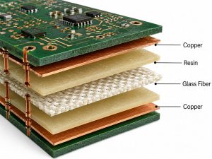
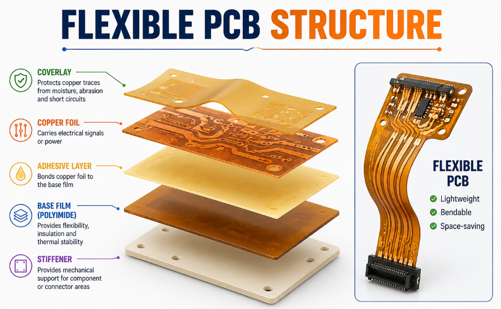
The most common flexible PCB material stack includes polyimide film, copper foil, adhesive or adhesiveless laminate, coverlay, solder mask, stiffener, and surface finish. Each material has a different function. The base film provides flexibility and insulation, copper carries signals or power, and coverlay protects the circuit.
For product development, choosing the right flexible PCB materials is not only a material decision. It affects mechanical reliability, electrical stability, manufacturing yield, assembly quality, and final product lifetime.
Why Are Flexible PCB Materials Important?
Flexible PCB materials are important because flexible circuits often work in tight spaces, moving areas, or products with strict size and weight limits. If the wrong material is selected, the circuit may suffer from copper cracking, delamination, poor solderability, insulation failure, short flex life, or unstable signal transmission.
A flexible PCB may look thin and simple, but its reliability depends heavily on the material stack. The base film, copper type, adhesive system, coverlay thickness, stiffener location, and surface finish must match the product’s bending condition and assembly process.
In mass production, material consistency is also critical. A small change in adhesive thickness, copper type, or coverlay opening may affect bend performance, impedance, dimensional accuracy, and component assembly quality.
How Do Flexible PCB Materials Work?
Flexible PCB materials work by combining a flexible insulating substrate with copper conductors and protective layers. The base film supports bending, the copper foil carries electrical current or signals, and the coverlay protects the traces from moisture, abrasion, and short circuits.
When a flexible PCB bends, the material stack experiences mechanical stress. The copper layer is usually the most vulnerable part because repeated bending can cause fatigue. That is why copper type, copper thickness, bend radius, and trace direction are important.
For high-reliability designs, flexible PCB materials must balance flexibility, adhesion, insulation, heat resistance, soldering compatibility, and dimensional stability. A good material stack allows the board to bend without damaging the circuit.
What Is the Structure of a Flexible PCB?
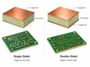
A typical flexible PCB includes base film, copper foil, adhesive or adhesiveless laminate, coverlay, surface finish, and optional stiffeners. The structure may change depending on whether the board is single-sided, double-sided, multilayer, or rigid-flex.
| Layer | Main Function | Key Selection Points |
|---|---|---|
| Polyimide base film | Supports flexibility and insulation | Thickness, heat resistance, dimensional stability |
| Copper foil | Carries current and signals | Copper type, thickness, bend life |
| Adhesive layer | Bonds copper to base film | Flexibility, thermal resistance, bonding strength |
| Coverlay | Protects copper traces | Thickness, opening accuracy, insulation |
| Surface finish | Protects exposed pads | Solderability, shelf life, assembly compatibility |
| Stiffener | Supports component or connector areas | Material, thickness, bonding method |
For most flexible circuits, the base film, copper foil, and coverlay determine the core mechanical reliability. Stiffeners are added only where extra support is needed, such as connector zones or component mounting areas.
What Base Films Are Used in Flexible PCB Materials?
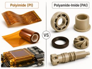
The base film is the foundation of a flexible PCB. It provides electrical insulation and mechanical flexibility. The most common base material is polyimide, while polyester and other films may be used in cost-sensitive or special applications.
| Base Film | Main Features | Common Use |
|---|---|---|
| Polyimide | High heat resistance, excellent flexibility, strong insulation | Most flexible PCB applications |
| Polyester | Lower cost, good flexibility, lower heat resistance | Simple low-cost circuits |
| LCP | Low moisture absorption, good high-frequency performance | RF, antenna, high-speed applications |
| PEN | Better heat resistance than PET, lower than PI | Selected flexible electronics |
Polyimide is widely used because it handles soldering heat better and supports stronger long-term reliability. For dynamic bending, compact electronics, and industrial products, polyimide is usually the preferred flexible PCB base material.
What Copper Foils Are Used in Flexible PCB Materials?
Copper foil is the conductive layer of a flexible PCB. It forms traces, pads, ground areas, and signal paths. The two common copper types are rolled annealed copper and electrodeposited copper.
| Copper Type | Typical Features | Best Use |
|---|---|---|
| Rolled annealed copper | Better ductility and flex fatigue resistance | Dynamic bending and repeated flexing |
| Electrodeposited copper | Cost-effective and widely available | Static flex or limited bending |
| Heavy copper | Higher current capacity | Power flexible circuits |
| Thin copper | Better flexibility and fine traces | Compact and fine-pitch designs |
Rolled annealed copper is often selected for applications that require repeated bending because it has better grain structure for flexing. Electrodeposited copper is common in applications where the circuit bends during installation but does not move repeatedly afterward.
What Adhesive Materials Are Used in Flexible PCB Materials?
Adhesive materials bond copper foil to the base film and help build the flexible laminate. Flexible PCBs may use adhesive-based materials or adhesiveless materials depending on reliability, thickness, and thermal requirements.
| Material Type | Advantages | Limitations |
|---|---|---|
| Adhesive-based laminate | Cost-effective, widely used, good bonding | Thicker stack, lower heat resistance than adhesiveless |
| Adhesiveless laminate | Thinner, better thermal performance, improved flex life | Higher cost, tighter process control required |
| Acrylic adhesive | Good flexibility and bonding | May have lower heat resistance |
| Epoxy adhesive | Good strength and stability | May be less flexible in repeated bending |
Adhesiveless flexible PCB materials are often preferred for high-reliability or fine-line circuits because they reduce thickness and improve bend performance. Adhesive-based materials remain practical for many standard applications where cost control matters.
What Coverlay Materials Are Used in Flexible PCBs?
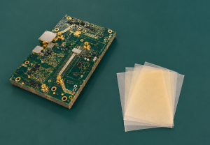
Coverlay is a protective layer used over copper traces on flexible PCBs. It usually consists of polyimide film with adhesive. Coverlay protects the circuit from scratches, moisture, dust, solder bridging, and mechanical damage.
Unlike standard solder mask on rigid PCBs, coverlay is more flexible and better suited for bending areas. It is especially important in circuits that move, fold, or pass through narrow mechanical spaces.
| Coverlay Factor | Why It Matters |
|---|---|
| Coverlay thickness | Affects flexibility and protection |
| Adhesive thickness | Affects bending and bonding reliability |
| Opening accuracy | Controls pad exposure and assembly quality |
| Heat resistance | Supports soldering and long-term operation |
| Flexibility | Prevents cracking during bending |
Coverlay openings must be designed carefully. If openings are too small, soldering may be difficult. If openings are too large, traces may lose protection near pads or bending areas.
What Stiffener Materials Are Used in Flexible PCB Materials?
Stiffeners are added to selected areas of a flexible PCB to provide mechanical support. They are not part of the electrical circuit, but they improve assembly, connector insertion, and component stability.
Common stiffener materials include FR4, polyimide, stainless steel, aluminum, and pressure-sensitive adhesive-backed materials. The choice depends on the required thickness, rigidity, temperature resistance, and assembly method.
| Stiffener Material | Common Use |
|---|---|
| FR4 stiffener | Component mounting, connector support |
| Polyimide stiffener | Flexible support with better heat resistance |
| Stainless steel stiffener | Strong mechanical support in thin areas |
| Aluminum stiffener | Lightweight support and heat spreading |
| PSA-backed stiffener | Fast bonding for selected applications |
Stiffeners should be placed only where needed. A poorly designed stiffener edge can create stress concentration and cause cracking near bending zones.
What Surface Finishes Are Used with Flexible PCB Materials?
Surface finish protects exposed copper pads and supports soldering. Common flexible PCB surface finishes include ENIG, OSP, immersion tin, immersion silver, HASL, and hard gold.
| Surface Finish | Main Advantages | Common Use |
|---|---|---|
| ENIG | Flat surface, good shelf life, stable soldering | Fine pitch, connectors, reliable assembly |
| OSP | Thin, economical, good for fast assembly | Cost-sensitive flexible circuits |
| Immersion tin | Good solderability and flatness | Selected connector and soldering areas |
| Immersion silver | Good conductivity and solderability | High-performance applications |
| HASL | Cost-effective | Less common for very thin flex |
| Hard gold | Wear resistance | Contact fingers and repeated mating areas |
ENIG is often used for flexible PCBs because it provides flat pads and reliable solderability. For contact fingers, hard gold may be required to handle repeated insertion or wear.
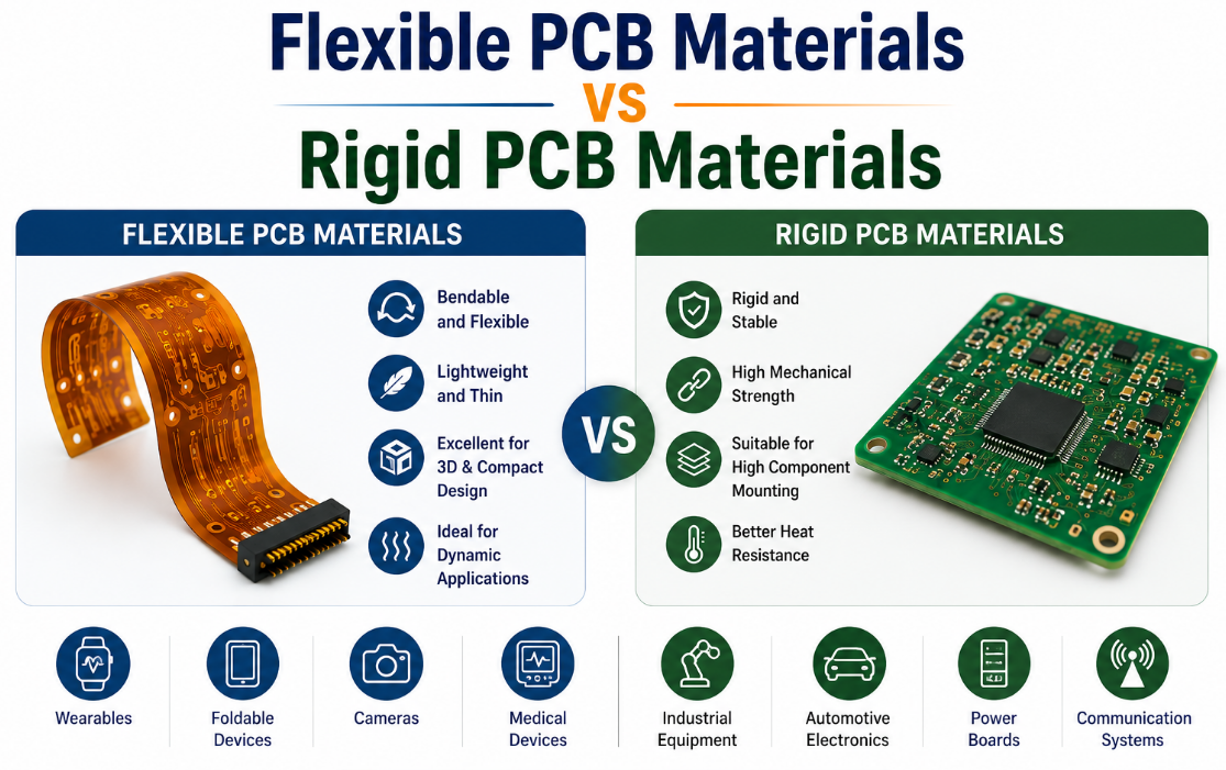
How Do Flexible PCB Materials Compare with Rigid PCB Materials?
Flexible PCB materials and rigid PCB materials are used for different mechanical needs. Rigid boards provide strong structural support, while flexible materials allow bending, folding, and compact installation.
| Comparison Item | Flexible PCB Materials | Rigid PCB Materials |
|---|---|---|
| Base material | Polyimide, PET, LCP | FR4, high Tg FR4, ceramic, metal core |
| Mechanical behavior | Bendable and lightweight | Rigid and stable |
| Space saving | Excellent | Limited in 3D layouts |
| Assembly support | May require stiffeners | Strong by default |
| Cost | Often higher than simple FR4 | Lower for standard boards |
| Best use | Compact, moving, foldable products | Main control boards and structural circuits |
| Design risk | Bend cracking and delamination | Warpage, cracking, thermal stress |
Flexible PCB materials are ideal when the product needs movement or compact packaging. Rigid PCB materials are better when the board must support heavy components, connectors, or mechanical loads.
How Do Flexible PCB Materials Compare with Rigid-Flex PCB Materials?
Flexible PCB materials are used in both flexible circuits and rigid-flex boards. The difference is that rigid-flex boards combine flexible sections with rigid PCB sections into one integrated structure.
| Comparison Item | Flexible PCB | Rigid-Flex PCB |
|---|---|---|
| Structure | Flexible circuit only | Rigid sections plus flexible sections |
| Assembly | Often needs connectors or stiffeners | Reduces connectors and cables |
| Cost | Lower than rigid-flex in many cases | Higher manufacturing cost |
| Reliability | Good when designed correctly | Better for complex compact assemblies |
| Space use | Very good | Excellent in 3D products |
| Best use | Simple bending or cable replacement | High-reliability compact electronics |
Rigid-flex PCB is usually selected when the product needs fewer connectors, higher assembly reliability, and compact three-dimensional packaging. Flexible PCB is often better when the design needs a simpler bendable circuit at lower cost.
What Bend Radius Should Be Considered for Flexible PCB Materials?
Bend radius is one of the most important factors for flexible PCB material selection. A smaller bend radius creates higher stress on copper traces and coverlay. If the bend radius is too tight, the flexible PCB may crack or delaminate.
The required bend radius depends on copper thickness, number of layers, base film thickness, adhesive type, coverlay thickness, and whether the bend is static or dynamic. Dynamic bending usually requires a larger bend radius and more careful material selection.
For safer design, traces should be routed perpendicular to the bend direction when possible, and copper should be kept away from sharp bend edges. The bend area should be as simple, thin, and stress-free as possible.
What Electrical Properties Should Be Checked?
Flexible PCB materials must provide stable electrical performance while bending or fitting into compact spaces. Important properties include dielectric strength, insulation resistance, impedance control, copper thickness, current capacity, dielectric constant, and moisture resistance.
| Electrical Property | Why It Matters |
|---|---|
| Dielectric strength | Prevents insulation breakdown |
| Insulation resistance | Reduces leakage current |
| Copper thickness | Supports current capacity |
| Dielectric constant | Affects high-speed and RF signals |
| Impedance control | Supports stable signal transmission |
| Moisture resistance | Improves reliability in humid environments |
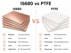
For high-speed, RF, or antenna applications, LCP or special low-loss materials may be considered. For standard industrial products, polyimide-based flexible PCB materials are often sufficient.
What Manufacturing Processes Are Used for Flexible PCBs?
Flexible PCB manufacturing includes material cutting, drilling, imaging, etching, coverlay lamination, surface finishing, electrical testing, profiling, stiffener bonding, and final inspection. The process requires careful handling because flexible materials are thin and easily deformed.
Common production steps include laminate preparation, copper patterning, drilling or laser processing, coverlay alignment, lamination, surface finish, outline cutting, electrical test, and packaging.
Manufacturing quality depends on precise control of coverlay openings, dimensional stability, adhesive flow, copper adhesion, and surface cleanliness. Poor process control may cause misalignment, wrinkles, delamination, or poor soldering results.
What Quality Tests Are Needed for Flexible PCB Materials?
Flexible PCB materials should be tested for mechanical, electrical, thermal, and assembly reliability. Quality control should check not only the circuit, but also the flexibility, adhesion, coverlay bonding, and dimensional stability.
| Test Item | Purpose |
|---|---|
| Visual inspection | Checks scratches, stains, coverlay defects, and exposed copper |
| Electrical test | Confirms open and short performance |
| Dimensional inspection | Checks outline, hole size, and pad position |
| Peel strength test | Confirms copper adhesion |
| Bend test | Evaluates flex performance |
| Solderability test | Confirms assembly readiness |
| Thermal stress test | Checks heat resistance |
| Insulation resistance test | Confirms electrical isolation |
For moving applications, bend testing is especially important. Static bend and dynamic bend requirements should be clearly defined before production.
What Common Problems Happen with Flexible PCB Materials?
Common problems include copper cracking, coverlay delamination, adhesive overflow, poor solderability, pad lifting, stiffener misalignment, trace fracture, impedance instability, and insulation failure.
Copper cracking often happens when the bend radius is too small, copper is too thick, or the wrong copper type is used. Delamination may come from weak bonding, moisture, poor lamination, or repeated thermal cycling. Stiffener misalignment can affect connector insertion and assembly accuracy.
Many failures can be avoided by reviewing the material stack early. The design should match bend type, bend radius, copper thickness, coverlay structure, stiffener placement, and assembly temperature.
How to Choose the Right Flexible PCB Materials?
Choosing the right flexible PCB materials starts with the product’s movement and environment. Confirm whether the board will be bent once during installation or flexed repeatedly during use. Then check thickness, copper type, base film, coverlay, stiffener, surface finish, and reliability requirements.
For dynamic bending, choose polyimide, rolled annealed copper, thinner copper, thinner dielectric, and smooth bend routing. For static bending, electrodeposited copper or adhesive-based materials may be suitable if the design is not highly stressed.
For high-temperature, automotive, medical, or industrial products, material selection should also consider thermal cycling, humidity, vibration, soldering process, chemical exposure, and lifetime expectations.
What Factors Affect the Cost of Flexible PCB Materials?
Flexible PCB material cost depends on base film type, copper type, copper thickness, layer count, adhesive type, coverlay thickness, surface finish, stiffeners, tolerance, testing, and order quantity.
| Cost Factor | Why It Affects Price | Cost Control Suggestion |
|---|---|---|
| Base film | Polyimide and LCP cost more than PET | Match material to real application needs |
| Copper type | Rolled annealed copper costs more than ED copper | Use RA copper where dynamic bending is required |
| Layer count | More layers increase lamination complexity | Keep flex areas simple where possible |
| Adhesiveless laminate | Improves performance but increases cost | Use for high-reliability or thin designs |
| Surface finish | ENIG and hard gold cost more | Choose by assembly and contact needs |
| Stiffeners | Add material and bonding steps | Use only where mechanical support is needed |
| Testing | Bend and reliability tests add cost | Apply critical tests to high-risk applications |
A low-cost flexible material may not be cheaper if it causes field failure. Cost control should focus on correct material selection, simplified bend zones, and stable manufacturability.
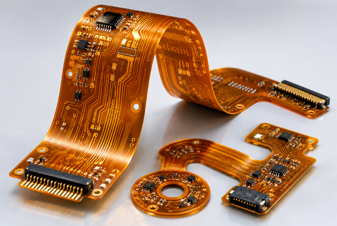
Where Are Flexible PCB Materials Commonly Used?
Flexible PCB materials are used in products that require lightweight circuits, movement, compact structure, or repeated bending.
Consumer electronics: smartphones, tablets, cameras, wearables, foldable devices, and display modules.
Automotive electronics: sensors, lighting, battery systems, dashboards, cameras, and control modules.
Medical devices: diagnostic equipment, wearable monitors, imaging devices, probes, and compact instruments.
Industrial equipment: sensors, robotic arms, control modules, HMI systems, and moving machine assemblies.
Aerospace and defense electronics: lightweight assemblies, compact modules, and high-reliability interconnects.
Communication products: antennas, RF modules, optical modules, and compact signal interconnects.
What Should You Confirm Before Ordering Flexible PCBs?
Before ordering flexible PCBs, confirm material stack, base film thickness, copper type, copper thickness, coverlay thickness, bend radius, surface finish, stiffener material, tolerance, and testing requirements.
You should also provide Gerber files, drill files, stack-up notes, drawings, bend area requirements, stiffener drawings, BOM if assembly is needed, quantity, and final application details.
For dynamic bending or high-reliability products, prototype validation is recommended before mass production. Testing under real bending, temperature, and assembly conditions helps reduce batch risk.
Why Choose EBest for Flexible PCB Manufacturing?
EBest Technology provides one-stop PCB solutions, including PCB design, PCB prototype, mass production, component sourcing, PCB assembly, and box-build assembly. Its product range includes standard FR4 PCB, multilayer PCB, metal-based PCB, ceramic PCB, flexible PCB, rigid-flex PCB, and high frequency PCB, supporting customers with different electronic manufacturing needs.
For flexible PCB projects, EBest can support material selection, stack-up review, prototype validation, batch production, assembly coordination, and quality inspection. This is useful when a project involves compact routing, connector areas, stiffeners, bend zones, and final product assembly.
EBest also supports quality and compliance systems such as IATF 16949, ISO 9001:2015, ISO 13485:2016, AS9100D, REACH, RoHS, and UL-related requirements. These capabilities help customers manage industrial, automotive, medical, aerospace, and export-oriented projects with more confidence.
FAQs About Flexible PCB Materials
Q1: What are flexible PCB materials made of?
A1: Flexible PCB materials usually include polyimide base film, copper foil, adhesive or adhesiveless bonding layers, coverlay, surface finish, and optional stiffeners. These materials work together to provide flexibility, insulation, electrical connection, mechanical support, and circuit protection.
Q2: What is the most common flexible PCB base material?
A2: Polyimide is the most common base material because it offers excellent heat resistance, strong insulation, good flexibility, and stable long-term performance. It is widely used in consumer electronics, automotive systems, medical devices, and industrial electronics.
Q3: What copper type is best for flexible PCB materials?
A3: Rolled annealed copper is often better for dynamic bending because it has stronger flex fatigue resistance. Electrodeposited copper is more cost-effective and suitable for static flex or applications where the board bends only during installation.
Q4: What is the difference between coverlay and solder mask?
A4: Coverlay is a flexible protective film, usually made from polyimide and adhesive. It is better for bending areas. Solder mask is more common on rigid PCBs and may not provide the same flexibility for repeated bending applications.
Q5: Are adhesiveless flexible PCB materials better?
A5: Adhesiveless materials can provide thinner structure, better thermal performance, improved dimensional stability, and better flex life. They are often used for high-reliability, fine-line, or dynamic bending applications, but they usually cost more.
Q6: How do I choose flexible PCB material thickness?
A6: Material thickness depends on bend radius, layer count, current load, mechanical space, and assembly needs. Thinner materials generally bend better, while thicker materials may provide stronger support but increase bending stress.
Q7: What causes copper cracking in flexible PCBs?
A7: Copper cracking may happen when the bend radius is too small, copper is too thick, the wrong copper type is used, or traces are placed poorly in the bend area. Proper material selection and bend design help prevent this issue.
Q8: Can flexible PCB materials support high-speed signals?
A8: Yes. Flexible PCBs can support high-speed signals when material dielectric properties, impedance control, copper roughness, trace geometry, and stack-up are properly designed. LCP or low-loss materials may be used for demanding RF applications.
Q9: Why are stiffeners used in flexible PCBs?
A9: Stiffeners provide mechanical support in selected areas, such as connectors, soldering zones, and component mounting locations. They help improve assembly stability but should not be placed in active bending zones unless carefully designed.
Q10: What surface finish is best for flexible PCBs?
A10: ENIG is commonly selected because it provides flat pads, good shelf life, and reliable soldering. OSP may be used for cost-sensitive and fast assembly projects, while hard gold is used for contact fingers or wear-resistant areas.
Q11: Are flexible PCB materials suitable for medical devices?
A11: Yes. Flexible PCB materials are widely used in medical devices because they support compact size, lightweight structure, and flexible interconnection. Material selection should consider reliability, cleanliness, insulation, biocompatible packaging, and long-term operating conditions.
Q12: What files are needed for a flexible PCB quotation?
A12: Provide Gerber files, drill files, stack-up requirements, copper thickness, base material, coverlay information, stiffener drawing, surface finish, quantity, bend radius requirements, and application details. For assembly, also provide BOM and placement files.
Conclusion
Flexible PCB materials determine how well a circuit can handle bending, insulation, soldering, current, thermal stress, dimensional control, and long-term reliability. The right material stack should be selected based on the real bending condition, operating environment, assembly process, and product lifetime target.
For product development, do not choose flexible PCB materials only by price or thickness. Review base film, copper type, adhesive system, coverlay, stiffener placement, surface finish, bend radius, and testing requirements before confirming the stack-up. For procurement, work with a manufacturer that can support prototype review, batch consistency, quality inspection, assembly coordination, and reliable delivery.
If you need flexible PCB materials, flexible PCB manufacturing, PCB assembly, OEM production, ODM development, sample testing, batch production, or custom engineering solutions, please contact our team at sales@bestpcbs.com for technical support and quotation service.