

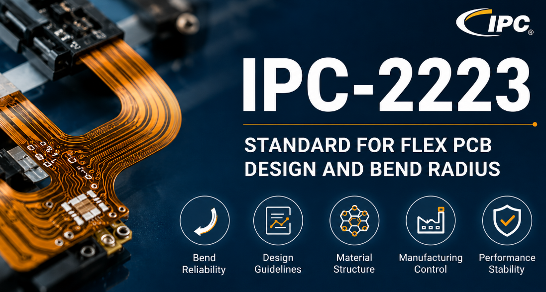
Is IPC-2223 affecting flex PCB bend reliability, production approval, and long-term product performance? Flexible and rigid-flex boards are widely used in compact electronic products, but small design errors can cause cracking, delamination, conductor fatigue, and costly project delays.
For this reason, IPC-2223 provides a structured reference for flex PCB design, bend radius control, material selection, and production documentation. When applied correctly, IPC 2223 helps improve reliability, reduce redesign, and support smoother project communication from quotation to delivery.
What is IPC 2223?
IPC 2223 is a sectional design standard for flexible and rigid-flexible printed boards. It works together with IPC-2221, which provides the general printed board design foundation, while IPC 2223 focuses on the special design requirements of flexible circuit structures.
Unlike rigid PCB guidance, this standard pays close attention to bend areas, flexible dielectric materials, conductor routing, coverlay openings, stiffeners, and rigid-to-flex transition zones. These details directly affect whether a flex PCB can survive assembly, installation, and long-term use.
In actual flex PCB projects, IPC 2223 works as a shared technical reference between the project side and the PCB manufacturer. It helps clarify stack-up, bend zones, hole placement, material structure, and reliability expectations before production starts.
What is the Latest Version of IPC-2223?
The current English version is IPC-2223E, released in January 2020. This revision is widely used for flexible and rigid-flex printed board design, especially where bend radius, manufacturing drawings, hole spacing, and flex-area conductor layout must be reviewed carefully.
Older versions such as IPC-2223A and IPC-2223D may still appear in legacy drawings, archived specifications, or old project documents. However, for new flex PCB projects, the active revision should be confirmed before quotation, design review, and production release.
A clear drawing note should state the applicable revision, such as IPC-2223E, together with other related standards. This avoids confusion when different teams refer to old internal files, outdated PDF copies, or supplier-side default requirements.
What is Difference between IPC 2223 Class 1, Class 2, Class 3?
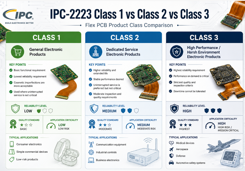
IPC 2223 Class 1, Class 2, and Class 3 define different reliability levels for flexible and rigid-flex PCB projects. The higher the class, the stricter the requirement for material control, manufacturing consistency, inspection, and long-term product performance.
| Class | Product Positioning | Reliability Level | Typical Applications | Design Focus | Quality Control Focus |
|---|---|---|---|---|---|
| Class 1 | General electronic products | Basic reliability | Toys, simple consumer products, low-cost electronic modules | Basic electrical function, simple flex structure, cost-sensitive layout | Visual quality, basic continuity, general dimensional control |
| Class 2 | Commercial and industrial products | Stable reliability | Industrial controls, communication devices, automotive accessories, medical support devices | Balanced bend radius, controlled stack-up, stable conductor routing, clear drawing notes | Electrical test, material consistency, plating quality, bend area inspection |
| Class 3 | High-reliability products | Highest reliability | Aerospace electronics, critical medical devices, military electronics, high-end industrial systems | Conservative bend radius, strict material selection, reinforced transition zones, optimized copper routing | Tight inspection, full documentation, strict acceptance criteria, higher process traceability |
| Cost Level | Lowest | Medium | Highest | Cost rises with tighter requirements | More testing and review increase total project cost |
| Production Risk | Lower requirement but less design margin | Moderate risk if data is clear | Higher control requirement but better long-term reliability | Class choice affects manufacturability | Clear class definition prevents later disputes |
| Best Fit | Short-life or simple-use products | Most commercial flex PCB projects | Products where failure may cause serious loss | Match class to product use | Avoid over-specifying or under-specifying |
Class selection should match the actual use environment, expected service life, and risk level. For many flexible PCB projects, Class 2 offers a practical balance between cost, reliability, and production control, while Class 3 is more suitable for critical applications with strict reliability targets.
What Does IPC-2223 Cover in Flex PCB Design?
IPC-2223 covers the design details that make flexible and rigid-flex boards manufacturable, bendable, and reliable. Its scope includes flex board types, material structures, component mounting forms, interconnection design, and mechanical reliability control.
The standard addresses single-sided, double-sided, multilayer, and rigid-flex constructions. It also considers adhesive and adhesiveless materials, insulating films, metallic conductors, reinforced or non-reinforced dielectric layers, and different flex circuit structures.
In real projects, IPC 2223 is useful for reviewing bend regions, conductor width, spacing, coverlay access, stiffener placement, via location, and transition areas between rigid and flexible sections. These design points directly affect yield, assembly stability, and field reliability.
Why is IPC-2223 Important for Flexible PCB Reliability?
IPC-2223 is important because flexible PCBs fail in different ways from rigid boards. A rigid PCB mainly faces thermal, electrical, and assembly stress, while a flex PCB also faces bending, folding, vibration, and mechanical movement.
If a bend area is designed with sharp corners, poor copper routing, unsuitable material thickness, or vias placed too close to the flex zone, the board can crack during installation or operation. Therefore, bend reliability must be treated as a core design target, not a final inspection item.
IPC 2223 helps reduce these risks by guiding how materials, conductor paths, and mechanical structures should be arranged. As a result, the project can gain better production yield, fewer quality disputes, and more stable performance after assembly.
What Materials and Structures Are Defined in IPC-2223 Flex PCB Design?
IPC-2223 defines flex PCB structures around insulating films, dielectric layers, adhesives, metallic conductors, coverlay, and stiffeners. These materials work together to provide both electrical connection and mechanical flexibility.
Common flex circuit materials include polyimide films, copper foil, adhesive systems, adhesiveless laminate, and protective coverlay. For rigid-flex boards, the structure also includes rigid laminate sections, plated through holes, and transition areas between rigid and flexible zones.
The material decision affects bend radius, thickness, heat resistance, dimensional stability, and cost. For example, thinner flexible layers usually support better bending performance, while added stiffeners can improve component mounting strength in selected areas.
IPC-2223 Specification for Flex PCB Design and Bend Radius
IPC-2223 specification focuses on the structure, bendability, material control, and reliability of flexible and rigid-flex printed boards. The following table summarizes key design areas that should be reviewed before production.
| Specification Area | Key Requirement | Design Purpose | Project Review Point |
|---|---|---|---|
| Flex Material | Polyimide, copper foil, adhesive or adhesiveless laminate | Support flexibility, heat resistance, and dimensional stability | Confirm material type, thickness, copper weight, and Tg requirement |
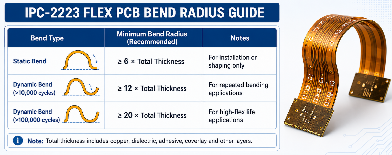
| Bend Radius | Radius must match total flex thickness and bend type | Reduce copper fatigue, cracking, and delamination | Define static bend or dynamic bend clearly on the drawing |
| Copper Routing | Traces should avoid sharp corners in bend areas | Improve stress distribution during bending | Use smooth routing and avoid sudden width changes |
| Via Placement | Vias should not be placed in active bend zones | Prevent barrel cracking and open circuits | Keep vias away from repeated bending areas |
| Coverlay Design | Openings must match pads and access areas | Protect conductors while keeping solderable areas exposed | Check coverlay registration and opening clearance |
| Stiffener Area | Stiffeners should support connectors or mounted parts | Improve mechanical strength where flexibility is not required | Define stiffener material, thickness, and location |
| Rigid-Flex Transition | Transition zones must avoid stress concentration | Protect copper and dielectric layers from cracking | Keep copper routing smooth near rigid-to-flex boundaries |
| Layer Stack-Up | Layer count and thickness must support the bend requirement | Balance circuit density and flexibility | Avoid excessive thickness in tight bend areas |
| Hole-to-Edge Spacing | Holes require safe spacing from board edge and bend zones | Reduce cracking and production defects | Review drilled holes, slots, and edge clearance |
| Drawing Notes | IPC class, material, bend radius, and surface finish should be defined | Reduce communication errors before production | Add clear notes for class level and special flex requirements |
This section is most valuable when used before quotation and production release. Clear IPC-2223 design data helps reduce redesign, sample failure, delivery delay, and quality disagreement.
How to Calculate Bend Radius for IPC-2223 Flex PCB?
Bend radius calculation should start from flex thickness, bend type, copper structure, and product movement conditions. A smaller product space does not automatically mean the flex circuit can accept a smaller radius.
Step 1: Confirm the total flex thickness.
Calculate the full flexible area thickness, including copper, dielectric film, adhesive, coverlay, and any additional protective layer. Thicker flex sections normally require a larger bend radius because the material stack is less flexible.
Step 2: Define the bending condition.
Confirm whether the flex PCB is bent once during installation or moves repeatedly during product operation. A static bend usually allows more design freedom, while dynamic bending requires more conservative structure and larger safety margin.
Step 3: Check copper layer count and copper weight.
More copper layers and heavier copper reduce flexibility. For tight bend areas, the structure should avoid unnecessary copper thickness, excessive layer count, and dense copper features that increase mechanical stress.
Step 4: Review the trace direction in the bend area.
Traces should pass through the bend area smoothly and should avoid sharp corners. Curved routing and gradual transitions help reduce stress concentration, especially in flexible circuits exposed to repeated movement.
Step 5: Keep vias, pads, and solder joints away from the bend zone.
These features are mechanically sensitive and may crack under bending stress. The bend area should remain as clean and simple as possible to improve long-term reliability.
Step 6: Match the bend radius with the manufacturing capability.
Before final release, the selected bend radius should be reviewed together with the PCB manufacturer. Material type, stack-up, production tolerance, and final assembly shape all affect whether the design is practical.
Step 7: Mark the bend radius clearly on the drawing.
The drawing should show bend direction, bend area, bend radius, stiffener location, and whether the bend is static or dynamic. Clear documentation helps prevent misinterpretation before sample production.
What Are Common Design Mistakes in IPC-2223 Flex PCB Projects?
Common IPC-2223 flex PCB mistakes usually come from ignoring mechanical stress in bend areas. Flexible circuits are not simply thin rigid boards, so the layout must consider bending, folding, installation pressure, and repeated movement.
- Placing vias inside the bend area
Vias are weak points under repeated bending. Placing them in active flex zones may cause barrel cracks, open circuits, or unstable electrical performance. - Using sharp trace corners in flexible regions
Sharp corners concentrate stress and increase the risk of copper fatigue. Smooth curves and gradual direction changes are better for bend reliability. - Choosing an overly thick stack-up
Too many layers, heavy copper, or thick dielectric materials make the flex area harder to bend. This can cause delamination, cracking, or poor installation fit. - Ignoring rigid-to-flex transition stress
The transition between rigid and flexible sections is a high-risk area. Poor copper routing or stiffener placement near this zone may create early failure. - Placing components too close to bend zones
Components, pads, and solder joints should stay away from flexible bending areas. Mechanical movement can damage solder joints or lift pads over time. - Leaving bend radius unclear on drawings
If the bend radius, bend direction, or bend type is not marked clearly, production review becomes unreliable. Ambiguous drawings often lead to sample delays or redesign. - Using unsuitable stiffener design
Stiffeners improve local strength, but poor placement can create stress at the edge. The stiffener boundary should be reviewed carefully in relation to the bend area. - Only checking electrical function
A flex PCB may pass electrical testing but still fail after bending. Mechanical reliability must be reviewed together with electrical performance.
How Does IPC-2223 Differ from IPC-2221 and IPC-6013?
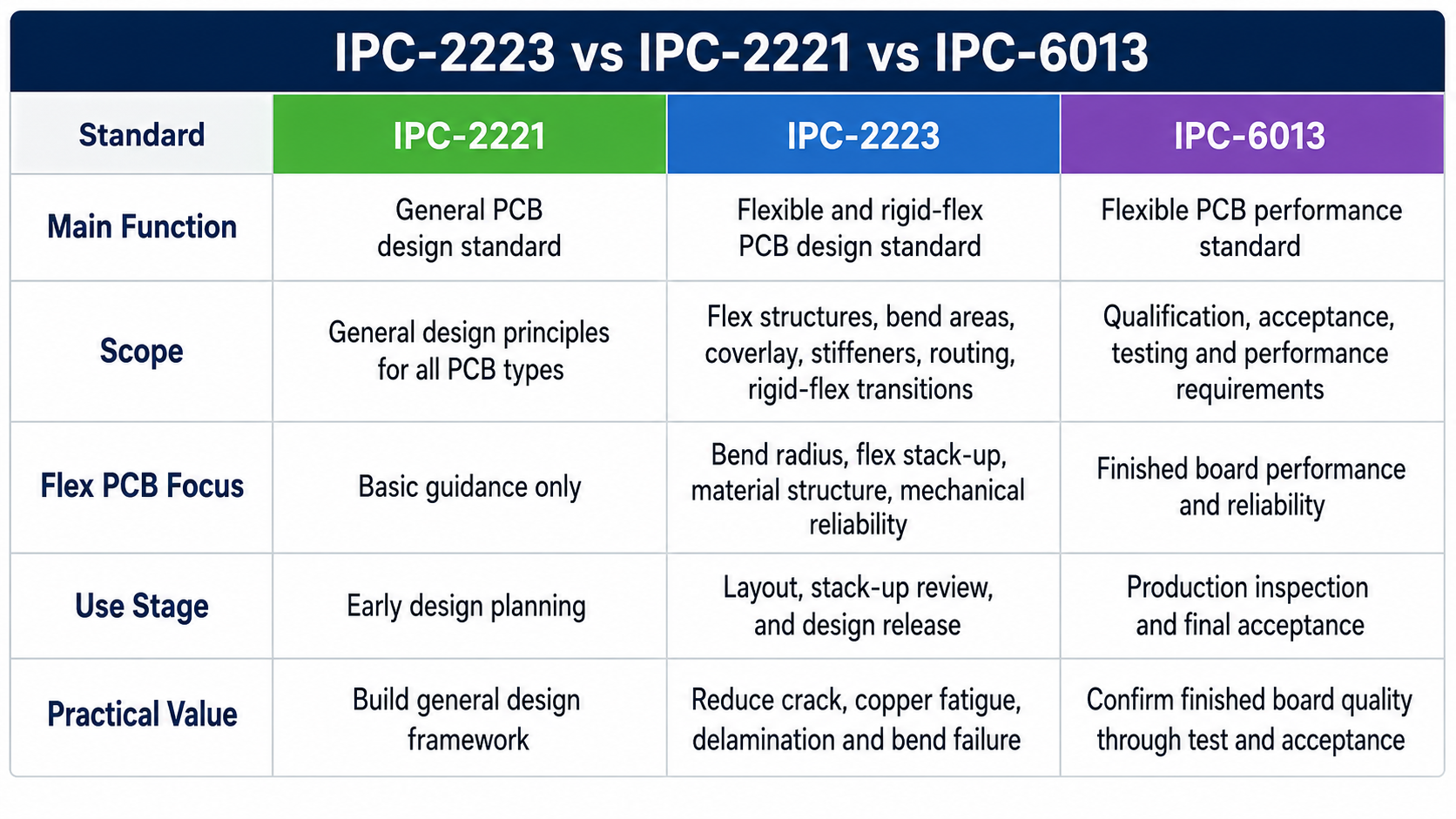
IPC-2223, IPC-2221, and IPC-6013 are related PCB standards, but they are used for different purposes in a flex PCB project. IPC-2221 gives the general design foundation, IPC-2223 focuses on flexible and rigid-flex PCB design, while IPC-6013 is mainly used for performance and qualification control.
| Standard | Main Function | Scope | Flex PCB Focus | Use Stage | Practical Value |
|---|---|---|---|---|---|
| IPC-2221 | General PCB design standard | Covers common printed board design principles for different PCB types | Provides basic design guidance, but does not deeply address bend radius, flex stack-up, or dynamic bending | Early design planning | Helps build a general design framework before applying flex-specific rules |
| IPC-2223 | Flexible and rigid-flex PCB design standard | Covers flex PCB structures, bend areas, coverlay, stiffeners, conductor routing, and rigid-flex transitions | Directly focuses on flex PCB design, bend radius control, material structure, and mechanical reliability | Flex PCB layout, stack-up review, and design release | Helps reduce cracking, copper fatigue, delamination, and bend-area failure |
| IPC-6013 | Flexible printed board performance standard | Covers qualification, acceptance, testing, and performance requirements for finished flexible boards | Focuses on whether the completed flex PCB meets quality and reliability requirements | Production inspection and final acceptance | Helps confirm finished board quality through measurable acceptance criteria |
In simple terms, IPC-2221 is the general design base, IPC-2223 is the flex PCB design guide, and IPC-6013 is the finished board performance reference. They should not be treated as interchangeable standards.
For a reliable flex PCB project, IPC-2223 is especially important during design review. IPC-6013 becomes more important after production, when the finished board must be checked against performance and acceptance requirements.
Where Can I Download IPC 2223 PDF?
IPC 2223 PDF should be obtained from official or authorized IPC channels. Since IPC standards are copyrighted documents, downloading free unofficial PDF copies can create version risk, compliance problems, and inaccurate technical references.
The safest method is to purchase or access the standard through the IPC store or authorized standards platforms. This helps ensure that the project uses the correct revision, correct language, and complete technical content.
For quotation or production review, sharing clear project requirements is usually better than sending an unclear downloaded file. A clear drawing note such as “Design reference: IPC-2223E” can help the PCB manufacturer understand the expected design basis. Attached is IPC 2223 PDF for your reference:
FAQs About IPC-2223 Standard
Q1: Is IPC-2223 only for flexible PCB projects?
A1: IPC-2223 is mainly used for flexible and rigid-flexible printed board design. It is especially valuable when the board includes bend areas, flexible material layers, coverlay, stiffeners, or rigid-to-flex transition zones.
Q2: Can IPC-2223 help reduce flex PCB cracking?
A2: Yes. IPC 2223 can help reduce cracking risk by guiding bend radius, conductor routing, material structure, and transition design. However, final reliability also depends on material choice, manufacturing control, assembly handling, and actual use conditions.
Q3: Is IPC-2223 enough for final product acceptance?
A3: IPC-2223 is a design standard, so it should not be used alone for final acceptance. For performance and qualification, projects often reference IPC-6013 together with the design requirements.
Q4: Should every flex PCB project use the same bend radius?
A4: No. Bend radius depends on flex thickness, copper weight, layer count, bend type, and movement frequency. A static bend can usually accept a different design margin than a dynamic flexing application.
Q5: Why do old drawings still mention IPC-2223A or IPC-2223D?
A5: Many legacy projects continue using old revision notes because the original product was approved years ago. For new projects, the revision should be reviewed and updated before design release or production transfer.
Q6: Does IPC-2223 apply to rigid-flex PCB stack-up review?
A6: Yes. IPC-2223 is highly relevant to rigid-flex stack-up review, especially where flexible layers pass through rigid sections, bend regions, plated holes, and transition areas.
Q7: What information should be confirmed before requesting a flex PCB quote?
A7: A quote request should include board type, layer count, material preference, copper thickness, bend radius, stiffener details, surface finish, class level, drawing notes, and expected annual quantity.
Get a Reliable Flex PCB Quote Based on IPC-2223 Requirements
A successful flex PCB project starts with clear design rules, reliable manufacturing control, and fast technical alignment. If your project involves bend radius limits, rigid-flex stack-up, tight assembly space, or high-reliability use, choosing a capable PCB partner can reduce risk before production begins.
EBest provides customized flex PCB and rigid-flex PCB manufacturing support with professional review, stable quality control, and responsive project communication. Send your Gerber files, drawings, stack-up, and IPC-2223 requirements to sales@bestpcbs.com to get a practical solution and fast quotation for your next flex PCB project.
You may also like


Tags: ipc 2223 bend radius, IPC 2223 latest version, ipc 2223 pdf, ipc 2223, ipc-2223 standard