





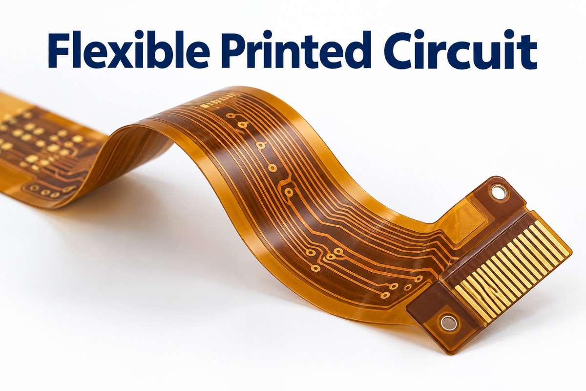
A flexible printed circuit (FPC) is an electrical circuit built on a thin, bendable insulating film, usually polyimide, with patterned copper conductors. It can connect boards, carry components, or follow a three-dimensional enclosure where a rigid PCB will not fit.
Flexibility does not mean unlimited bending. A circuit folded during installation and one moving inside a hinge need different constructions. The materials, bend zone and connector ends must be designed together.
How Does a Flexible Printed Circuit Work?
An FPC carries power and signals through copper tracks just as a rigid PCB does; its thin film substrate lets those tracks follow a controlled bend. The copper is patterned into separate conductors, while insulating layers prevent contact between adjacent circuits.
A flexible printed circuit board can include pads, vias and mounted components, not just parallel wires. In a camera module, for example, one custom-shaped flex can route signals from the sensor board around a mechanical obstruction to the main board. Component locations remain supported while the connecting section bends.
What Are the Main Types of Flex Circuits?
The main constructions are single-sided, double-sided and multilayer flex; rigid-flex combines flexible interconnect sections with integrated rigid circuit sections.
| Construction | Copper structure | Typical reason to choose it |
| Single-sided flex | One conductive layer | Simple routing with a thin bend region |
| Double-sided flex | Two conductive layers, usually joined by plated holes | More routing paths or a reference layer |
| Multilayer flex | Three or more conductive layers | Dense routing where a thicker stack is acceptable |
| Rigid-flex | Rigid circuit sections integrated with flex layers | Rigid component areas connected without separate cable connectors |
Adding layers increases routing space but also changes bending stiffness. A multilayer design that fits a stationary enclosure is not automatically suitable for repeated movement.
Which Flexible Printed Circuit Board Material Should You Choose?
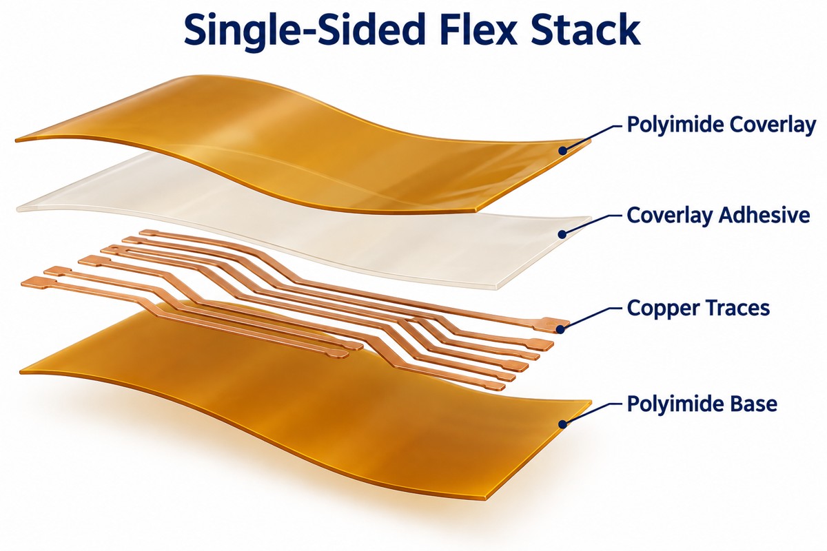
Polyimide with copper foil is a common choice for soldered FPC assemblies; the copper type, adhesive system and protective coverlay must then match the temperature and bending requirements.
- Base film: polyimide provides electrical insulation and tolerates the thermal processing used for many assembled flex circuits. Polyester is an alternative for suitable lower-temperature constructions, not an automatic replacement in a reflow-soldered design.
- Copper: rolled-annealed copper is commonly evaluated for repeated flexing. Electrodeposited copper is also used, but foil grade and fatigue performance matter more than the abbreviation alone.
- Laminate: adhesive-based constructions bond copper to film with an adhesive layer. Adhesiveless laminates remove that separate bonding layer from the copper-to-polyimide interface, helping reduce stack thickness.
- Coverlay: a protective film and adhesive cover the tracks, with openings at solder pads and contacts.
For a concrete coverlay example, DuPont Pyralux LF7001 combines 13 µm adhesive with 13 µm polyimide, while LF0110 lists 25 µm for each. These are individual coverlay constructions, not finished FPC thicknesses.
How Is an FPC Different from an FFC or a Rigid PCB?
An FPC has a custom circuit pattern, an FFC typically has parallel flat conductors, and a rigid PCB uses a substrate intended to stay rigid.
| Feature | FPC | FFC | Rigid PCB |
| Routing | Custom tracks, branches and pads | Usually parallel conductors | Custom tracks, planes and vias |
| Form | Custom outline with designed bend zones | Usually a flat ribbon | Fixed board shape |
| Component mounting | Possible on supported areas | Usually used as an interconnect cable | Standard component platform |
An FFC can be the simpler option for a straight connection between compatible sockets. Choose FPC when the circuit needs branching, an unusual outline, components or controlled routing. A flex board with a bonded stiffener is still not the same as an electrically integrated rigid-flex board.
How Do Static and Dynamic Bending Change the Design?
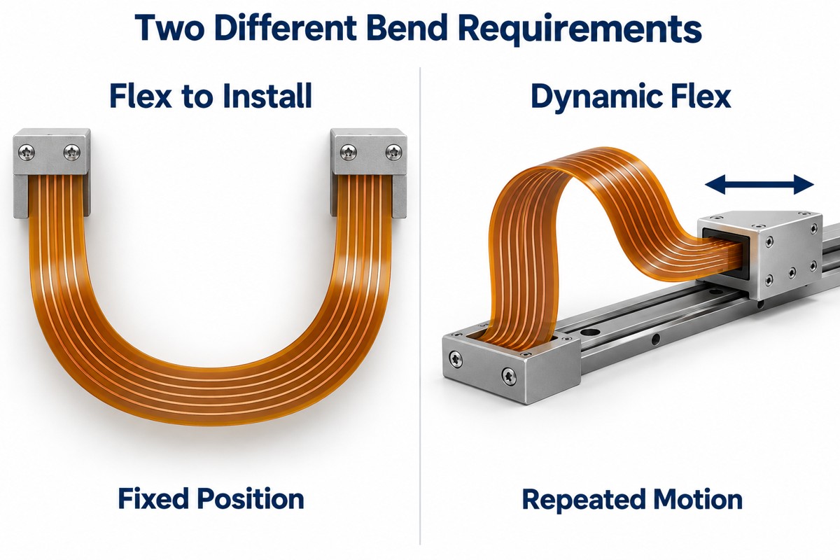
Static, or flex-to-install, circuits are bent into position and normally remain there; dynamic circuits must survive repeated movement without conductor fatigue.
For installation-only routing, define the formed shape, bend radius and assembly sequence. For dynamic routing, also specify the travel, cycle requirement, speed and operating environment. A hinge that passes one assembly bend has not demonstrated its service life.
- Keep components, solder joints and plated holes outside the working bend zone.
- Route conductors across the bend line rather than along it, and avoid abrupt changes in width.
- Use smooth curves instead of creases; keep the moving section clear of sharp enclosure edges.
- Evaluate the thinnest practical stack and suitable copper foil before adding layers or shielding.
How Is the Minimum Bend Radius Determined?
The minimum bend radius comes from the complete flex stack and required bend life, not from the polyimide thickness alone. Copper, adhesive and coverlay all contribute to the thickness and strain of the bend region.
For example, our rigid-flex DFM guide gives 6× composite thickness for single- and double-sided flex sections and 12× for sections with three or more copper layers. Under that guide’s construction assumptions, a 0.10 mm section at 6× gives a 0.60 mm radius. These are design guidelines, not a guarantee for every FPC or dynamic application.
Record the approved radius on the drawing and validate the actual construction at the required motion and temperature. Changing the copper thickness, shielding or coverlay after approval can invalidate the earlier bend assessment.
How Do You Match a Flexible Printed Circuit Connector?
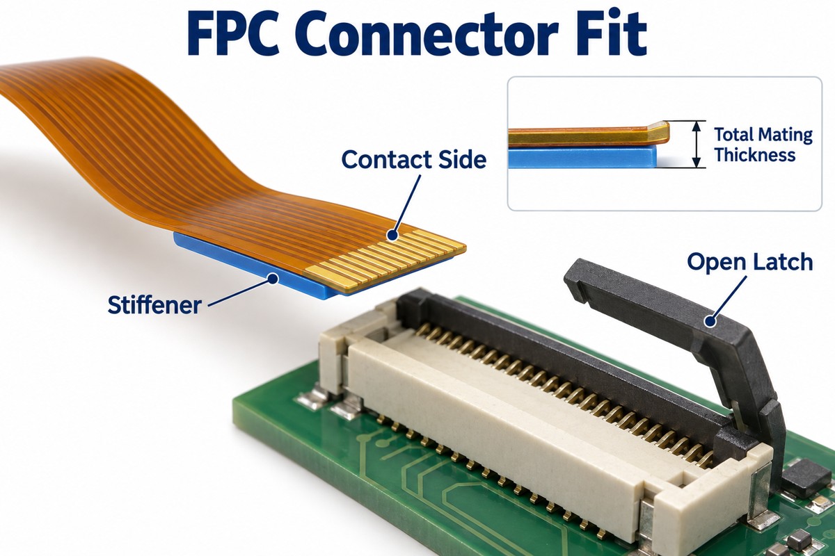
Match the connector’s pitch, position count, contact side and specified FPC mating thickness before finalizing the tail drawing. Matching the number of contacts alone is not enough.
For example, Hirose FH12 is an FPC/FFC connector family offering 0.5 mm and 1 mm pitches. The exact part drawing determines the contact orientation and acceptable tail dimensions; the family name is not a complete interface specification.
- Contact geometry: confirm finger width, pitch, exposed length and edge-to-contact dimensions.
- Mating thickness: include the circuit, bonded stiffener and adhesive at the insertion area.
- Contact side: verify whether the socket contacts the upper or lower face of the inserted tail.
- Retention: allow access to the latch and keep cable pull or bending loads away from the connection.
A local PCB stiffener can support the tail and establish its mating thickness. Its edge should not force bending directly beside exposed contacts or solder joints.
Flexible Printed Circuit Manufacturing Process
The flexible printed circuit manufacturing process patterns copper on a flexible laminate, forms any required interlayer connections, adds insulation and reinforcement, and tests the finished circuit.
- Prepare the laminate: select the specified copper-clad film and prepare the panel for imaging.
- Form the circuit: image and etch the copper tracks; drill and plate interconnections where the construction requires them.
- Protect the conductors: align and laminate coverlay with openings for pads and contacts.
- Complete exposed surfaces: apply the specified pad or contact finish and bond local stiffeners.
- Profile and test: cut the outline, inspect dimensions and check electrical continuity and isolation.
The exact sequence changes with layer count, via structure and finish. The etched FPC process explains copper pattern formation in more detail. Coverlay registration and adhesive flow deserve particular attention because a partly covered contact may not mate or solder correctly.
What Changes When Components Are Assembled on Flex?
Flex assembly needs support beneath the circuit during printing, placement and soldering so the thin panel stays flat and the joints remain unloaded.
- Carrier or fixture: support the panel without obstructing pads or distorting the intended outline.
- Moisture control: follow the laminate and assembly process requirements before thermal exposure; do not apply one universal baking recipe.
- Reflow profile: qualify the temperature profile against the solder paste, components and complete flex material system.
- Inspection: check solder joints and pad alignment, then use electrical or functional testing appropriate to the assembly.
After soldering, handle the assembly by supported areas. Pulling a loose tail to lift the board can transfer force into small pads or joints even when the soldering itself was acceptable.
Where Are Flexible Printed Circuits Most Useful?
FPCs are useful where a circuit must fit a narrow three-dimensional space, connect moving sections or reduce separate wire connections.
- Cameras and displays: connect modules arranged on different planes.
- Wearable devices: follow compact enclosure shapes and connect small component islands.
- Medical instruments: route signals through constrained assemblies with application-specific material and reliability requirements.
- Battery monitoring: distribute sensing connections across a cell arrangement without treating thin sensing traces as the main power bus.
- Moving mechanisms: use a qualified dynamic flex section where the motion profile suits the construction.
For a flat assembly with ample space and no movement, a rigid PCB may be easier and less expensive. FPC is valuable when its geometry solves a real packaging or interconnection problem.
FAQ About Flexible Printed Circuits
Can an FPC be stretched?
Not like an elastic band. Conventional polyimide-and-copper flex is designed to bend, not stretch freely. Stretchable electronics require different materials or conductor geometries.
Can a torn flex circuit be repaired?
Some accessible traces can be repaired in controlled rework, but a repair changes local stiffness and may not survive repeated bending. Replacement is usually more appropriate for damaged moving sections or contacts that must fit a socket precisely.
Can flex carry high-speed signals?
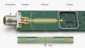
Yes, with a designed transmission-line structure. Specify the impedance target, reference conductors, dielectric thickness and connector transition; bending and any change from solid to hatched shielding should be included in the assessment.
Is every amber flex circuit made from the same material?
No. Color does not identify the laminate grade, copper type or adhesive. The material specification and stackup are the reliable references.
What makes a custom FPC expensive?
More layers, complex outlines, poor panel utilization, fine features, multiple stiffeners and special materials can add cost. Compare quotations using the same construction and test requirements rather than board area alone.
How Can EBest Circuit Support Your Flex Circuit Project?
At EBest Circuit, we support flexible PCB and rigid-flex projects from prototype fabrication through production and assembly. Our PCB and PCBA services date back to 2006, and we can review the circuit, component sourcing and assembly requirements together.
For your flexible circuit project, send the Gerber or ODB++ data, stackup, bend drawing, connector part number and quantity to sales@bestpcbs.com. If assembly is required, include the BOM and placement data. We will review the material construction, reinforcement and manufacturing requirements before confirming a quotation.
You may also like




Tags: flexible printed circuit, flexible printed circuit board, flexible printed circuit board material, flexible printed circuit connector, flexible printed circuit manufacturing process