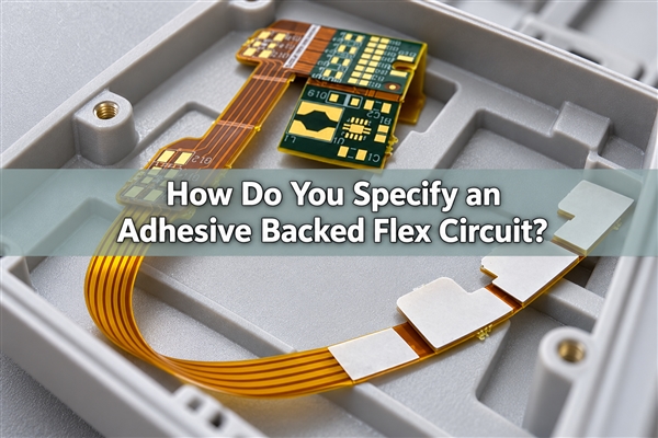
An adhesive backed flex circuit combines a flexible printed circuit with a mounting adhesive on selected areas of its rear surface. A removable liner protects the adhesive until installation. The result is a low-profile electrical interconnect that can be fixed inside a housing without adding a fastener at every mounting point. Reliable mounting depends on the housing surface, adhesive pattern, assembly temperature and loads at the free flex tail, not simply on choosing a tape that feels sticky.
What Is an Adhesive Backed Flex Circuit?
An adhesive backed flex circuit is usually a finished flex PCB with a pressure-sensitive adhesive, or PSA, added for mechanical attachment. The copper traces carry the electrical signals; the backing holds designated regions in position. Removing the release liner exposes the adhesive for bonding to the specified surface.
The adhesive does not have to cover the whole board. Separate mounting islands can secure component areas while leaving a tail free to reach a connector. This is useful when a housing has limited room for clips, or when an interconnect must follow a fixed route between two boards. The mounting outline and the electrical circuit outline are therefore separate drawing features.
Is Adhesive Backing the Same as an Adhesive-Based Flex Core?
No. Adhesive backing sits outside the finished circuit for installation. An adhesive-based flex core uses an internal bonding layer between copper and the insulating film. Coverlay adhesive has another job: attaching the protective coverlay over the etched circuit.
An adhesiveless flex circuit can still have mounting adhesive on its back. “Adhesiveless” describes the core construction, not necessarily every layer added to the finished part. For an adhesive flex PCB quotation, send us a drawing that identifies whether the adhesive belongs in the core, under a stiffener or on the rear mounting surface. These locations require different constructions and production steps.
A bonded stiffener also does not turn a flex PCB into a rigid flex circuit. A rigid-flex board integrates electrically interconnected rigid and flexible sections. A stiffener attached to the back of a flex circuit primarily supplies mechanical support.
Which Adhesive Should You Use for a Flex Circuit?
Select the flex circuit adhesive against both mating surfaces and the required function. For ordinary mounting, a nonconductive acrylic PSA may be suitable, but adhesion to bare metal, painted metal and molded plastic can be very different. Specify the actual finish, including coatings or mold-release residues, rather than just writing “plastic enclosure.”
- Mechanical retention: evaluate peel resistance, shear creep and edge lifting on the intended housing material.
- Heat transfer: use a material with documented thermal properties and assess the complete heat path; ordinary mounting tape is not automatically a thermal interface material.
- Electrical grounding: a conductive adhesive needs a designed exposed ground contact and a suitable mating conductor. Nonconductive PSA does not provide that connection.
- Component support: compare a PSA-attached stiffener with a laminated stiffener against soldering temperature and mechanical loads.
A flexible circuit board adhesive that performs well in a room-temperature peel test may still creep under continuous heat and load. For a connector tail, the force direction matters as much as the adhesive area: a pull that peels one edge can be more demanding than a distributed in-plane load.
Which Adhesive Parameters Should Be on the Drawing?
The drawing should identify the adhesive grade, installed thickness, pattern, position tolerance, mating surface and exposure conditions. Material data also needs its test method and conditioning time. Without those details, two numerical peel-strength values are not directly comparable.
| Parameter | Example or required entry | How to use it |
|---|---|---|
| Adhesive thickness | 3M 467MP: 0.06 mm; 468MP: 0.13 mm in the cited family data | Identify the exact grade and datasheet revision; these are material examples, not a mandatory flex stack-up. |
| Release liner | 467MP example: 0.11 mm polycoated kraft liner | Include it in delivery/handling thickness, but exclude it from the installed assembly after removal. |
| 90-degree peel adhesion | 467MP: 10 N/cm on stainless steel after 72 hours at room temperature | Typical ASTM D3330 result with aluminum-foil backing; not a finished-flex acceptance limit. |
| PSA outline and cutouts | Dimensioned drawing in mm, referenced to board datums | Define edge setback, holes, exposed pads and no-adhesive areas. |
| Position tolerance | Agreed bilateral or profile tolerance in mm | Check combined flex-outline, adhesive-cut and placement variation. |
| Thermal exposure | Operating temperature, peak process temperature, duration and number of cycles | Separate service exposure from soldering and rework. |
| Bond qualification | Peel angle/rate, dwell, surface preparation, load, environment and acceptance limits | Use repeatable tests on the actual bonded materials. |
The numerical material examples above come from the 3M 467MP technical data sheet, May 2017. They describe typical material properties under stated conditions, not our finished-board test results. The ordered grade and current approved specification govern production.
Keep the installed thickness calculation separate from shipping thickness. For example, an assumed 0.15 mm finished flex plus 0.06 mm adhesive gives 0.21 mm before compression and tolerances. Adding a 0.11 mm removable liner gives 0.32 mm as delivered. This arithmetic example is not a recommended circuit thickness; components, stiffeners and their tolerances must be added wherever present.
Where Should Adhesive Be Placed on a Flexible PCB?
Place adhesive where the circuit must remain fixed, and keep the intended moving or installation-bend region free unless the design specifically qualifies a bonded fold. Do not run a backing layer across connector contacts, test pads or openings that must remain accessible.
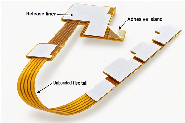
Dimension each adhesive island from a defined board datum. A drawing should also show the mounting side, orientation and exclusion zones. Small disconnected patches can be difficult to handle and align, so the smallest feature must be reviewed together with the intended cutting and placement process rather than assigned a universal minimum size.
At the end of a bonded region, avoid forcing the free tail around a sharp enclosure edge. Provide a smooth transition and a supported routing path. If the tail plugs into a connector on an FR4 PCB, set its installed position from the connector location and insertion direction, not only from the housing wall. Adhesive should retain the route without preloading the connector.
How Do Release Liners Affect Flex Circuit Assembly?
The liner determines how easily an operator can expose and position the adhesive without damaging the flex. A fully flush liner can be difficult to start, especially beside a narrow tail. A pull tab or split liner can provide a controlled gripping point while keeping the adhesive protected.
Specify which region is peeled first and whether the part is located by a fixture, a housing feature or a visual reference. The operator should be able to position the circuit before applying final bonding pressure. A liner tab must remain accessible at that stage; a tab trapped under the circuit or a nearby component defeats its purpose.
Check liner removal during prototype assembly, not just on a flat drawing. If the flex bends sharply when the liner is pulled, support the circuit close to the peel front. Avoid using a connector tail or a populated area as the handle.
Can Adhesive-Backed Flex Circuits Go Through Reflow?
Only when the exact adhesive and liner system is qualified for the complete thermal profile. A short-term heat-resistance value alone does not establish compatibility with reflow, repeated soldering or subsequent cleaning.
One practical route is to assemble and clean the circuit first, then apply the mounting PSA. Another is to use a verified assembly-compatible adhesive before soldering. The correct sequence depends on access to the rear surface, support tooling and the approved material. Do not infer reflow suitability from the polyimide substrate rating; the adhesive or liner can be the limiting layer.
For our PCB assembly service, we support SMT, through-hole and mixed assembly, with capabilities down to 01005 components and 0.25 mm BGA pitch on suitable projects. Flex handling, support fixtures and adhesive processing still need project-specific review. Include the adhesive operation in the assembly drawing and BOM so it is not treated as an unspecified step after soldering.
How Do You Install a Peel-and-Stick Flex Circuit?
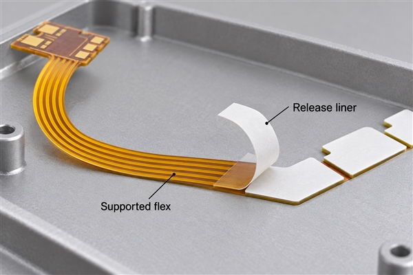
Install the circuit on a clean, dry and compatible surface, locate it without stretching the tail, and apply controlled pressure to the intended bonded areas. The adhesive manufacturer’s preparation, temperature and dwell instructions should become part of the assembly procedure.
- Inspect the receiving surface. Check for oil, dust, loose coating, rough edges and geometry that prevents contact. Confirm that the specified cleaning method is compatible with both materials.
- Dry-fit with the liner in place. Verify connector reach, bend position, component clearance and access to liner tabs.
- Expose the intended adhesive region. Handle the liner, not the adhesive, and support the flex as the liner is removed.
- Locate and bond progressively. Use the agreed datum or fixture. Avoid trapping wrinkles or stretching the circuit to meet a misplaced reference.
- Apply pressure with appropriate support. Support the opposite side; do not press directly on fragile components or unsupported tails.
- Allow the specified dwell and inspect. Confirm alignment, edge contact and electrical continuity before applying the full service load.
Record the installation conditions when a prototype fails. Repeating a test with a freshly cleaned housing, a different dwell time and a different peel direction creates a different test, not a direct repeat of the first result.
Adhesive Backing vs Mechanical Mounting: Which Should You Choose?
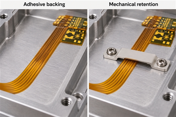
Adhesive backing suits low-profile retention over a defined surface. Mechanical mounting is often preferable where disassembly, concentrated loads or positive location dominate. A hybrid design can use adhesive to keep a flex route flat and a separate feature to carry connector or cable loads.
| Design need | Adhesive backing | Clips, clamps or fasteners |
|---|---|---|
| Limited height | Thin bond line with no fastener head in the bonded region | Needs space for the retaining feature and assembly access |
| Repeated servicing | Removal can damage the flex or leave residue; replacement may be needed | Can provide a planned release mechanism |
| Continuous pull or heat | Requires creep testing for the actual area and load direction | Can transfer load into a designed structural feature |
| Surface variation | Sensitive to contamination, texture and coating adhesion | Less dependent on surface chemistry, but fit and clamp pressure matter |
| Moving tail | Retain stationary regions, leaving a controlled free transition | Provide strain relief without pinching or creating a sharp bend |
A thicker adhesive is not automatically a substitute for a clamp. Likewise, adding a screw near a thin flex does not automatically make the assembly stronger: local pressure, hole support and trace clearance need a designed load path.
What Causes Adhesive-Backed Flex Circuits to Lift or Slip?
Lifting usually indicates a local separation or peel load, while slipping suggests movement within the bond or at an interface. Similar-looking failures can have different causes. Preserve the failed surfaces and compare the result with the installation record before changing the adhesive grade.
| Observed condition | What to check | Useful next step |
|---|---|---|
| One edge lifts after the tail is connected | Tail preload, connector position, abrupt bend at the bonded edge | Test the same bond with the tail unloaded, then correct routing or strain relief |
| Patch shifts during hot dwell | Shear load, temperature, bonded area and adhesive creep | Repeat with recorded load and displacement over time |
| Adhesive releases from a painted housing | Adhesive-to-paint interface versus paint-to-housing separation | Inspect both faces; qualify the actual coating system |
| Wrinkle or unbonded pocket | Placement sequence, flatness, local particles and support tooling | Review the installation method and contact pattern |
| Electrical failure after repositioning | Creased copper, torn coverlay or stressed joints | Inspect the circuit and test continuity; stronger tape will not repair trace damage |
How Should You Test an Adhesive-Backed Flex Circuit?
Test mechanical retention and electrical function separately, then combine them under the intended environment. A continuity pass does not prove the bond is stable, and a strong peel result does not prove the copper survived installation.
- Peel: fix the angle, rate, sample width, dwell and substrate. Report force per width and where separation occurred.
- Static shear: define bonded area, applied load, orientation, temperature and duration. Record movement or time to failure.
- Environmental exposure: use the specified heat, humidity or chemical conditions, then repeat the relevant retention and electrical checks.
- Installation trial: evaluate liner handling, alignment, wrinkles and connector loading using the actual enclosure or a representative fixture.
- Electrical checks: compare continuity and insulation results before and after installation and environmental exposure, using the approved circuit test requirements.
Test coupons are useful for isolating material behavior, but a flat strip does not reproduce every stress in a populated flex assembly. Include the real adhesive boundary, tail routing and housing finish in final qualification. Agree acceptance limits before testing rather than choosing them after the results are known.
What Files Are Needed for an Adhesive-Backed Flex PCB Quote?
Send the circuit fabrication data together with a separate, dimensioned adhesive drawing. At EBest Circuit (Best Technology), we provide flexible and rigid-flex PCB manufacturing and assembly support. The quotation needs to distinguish the electrical board, mounting adhesive, liner and any post-assembly application work.
- Gerber or other accepted fabrication files, drill data and the required flex stack-up.
- Adhesive grade or functional requirements, with any approved-alternative restrictions.
- Adhesive side, outline, openings, placement datums and tolerances.
- Liner material, pull tabs, split positions and removal sequence.
- Housing material and finish, installed geometry, load direction and operating environment.
- BOM and assembly files for populated parts, plus soldering, cleaning and adhesive-application sequence.
- Prototype and production quantities, inspection requirements and packaging expectations.
Email sales@bestpcbs.com with the drawing and intended mounting surface. We can review the fabrication and assembly requirements together, identify unresolved adhesive details before quoting, and define what the delivered circuit includes. A tape part number without its placement and process requirements is not a complete manufacturing specification.
Adhesive Backed Flex Circuit FAQs
1. Is flex circuit tape electrically conductive?
Not necessarily. Flex circuit tape can mean ordinary mounting PSA, insulating tape or a specialized conductive product. For grounding, specify conductivity direction, exposed contact geometry and resistance requirements; do not rely on the word “tape.”
2. Can you remove and reuse an adhesive-backed circuit?
Do not assume reuse is acceptable. Removal may distort the circuit or contaminate the adhesive. A serviceable design needs a defined release method and replacement criteria, including electrical checks if the circuit is retained.
3. Does adhesive backing make a flex circuit waterproof?
No. A mounting bond alone does not establish an enclosure ingress rating. Edges, connectors, holes and material interfaces still need a sealing design and appropriate testing.
4. Does an adhesive circuit replace soldered connections?
A mechanically mounted adhesive circuit still needs its specified electrical termination. Backing adhesive normally holds the board in position; it does not replace connector contacts or solder joints. Conductive bonding is a separate interconnection design.