PCB manufacturing PCB manufacturing
Home > Blog

thermal conductivity

Ceramic PCB High Temperature Resistant Guide: Materials, CTE and Thermal Conductivity
Friday, July 10th, 2026

A ceramic PCB can be a strong choice for high temperature electronics when FR4, standard metal core PCB, or ordinary laminate materials cannot provide enough temperature stability, insulation, or heat transfer. The right material still depends on actual operating temperature, heat load, thermal cycling, CTE matching, copper structure, assembly method, and inspection requirements.

What Does Ceramic PCB High Temperature Resistant Mean?

Ceramic PCB high temperature resistant means the circuit substrate can keep useful electrical insulation, dimensional stability, and mechanical integrity in a hotter environment than many organic PCB materials can tolerate.
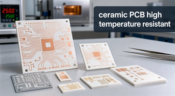
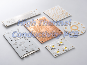
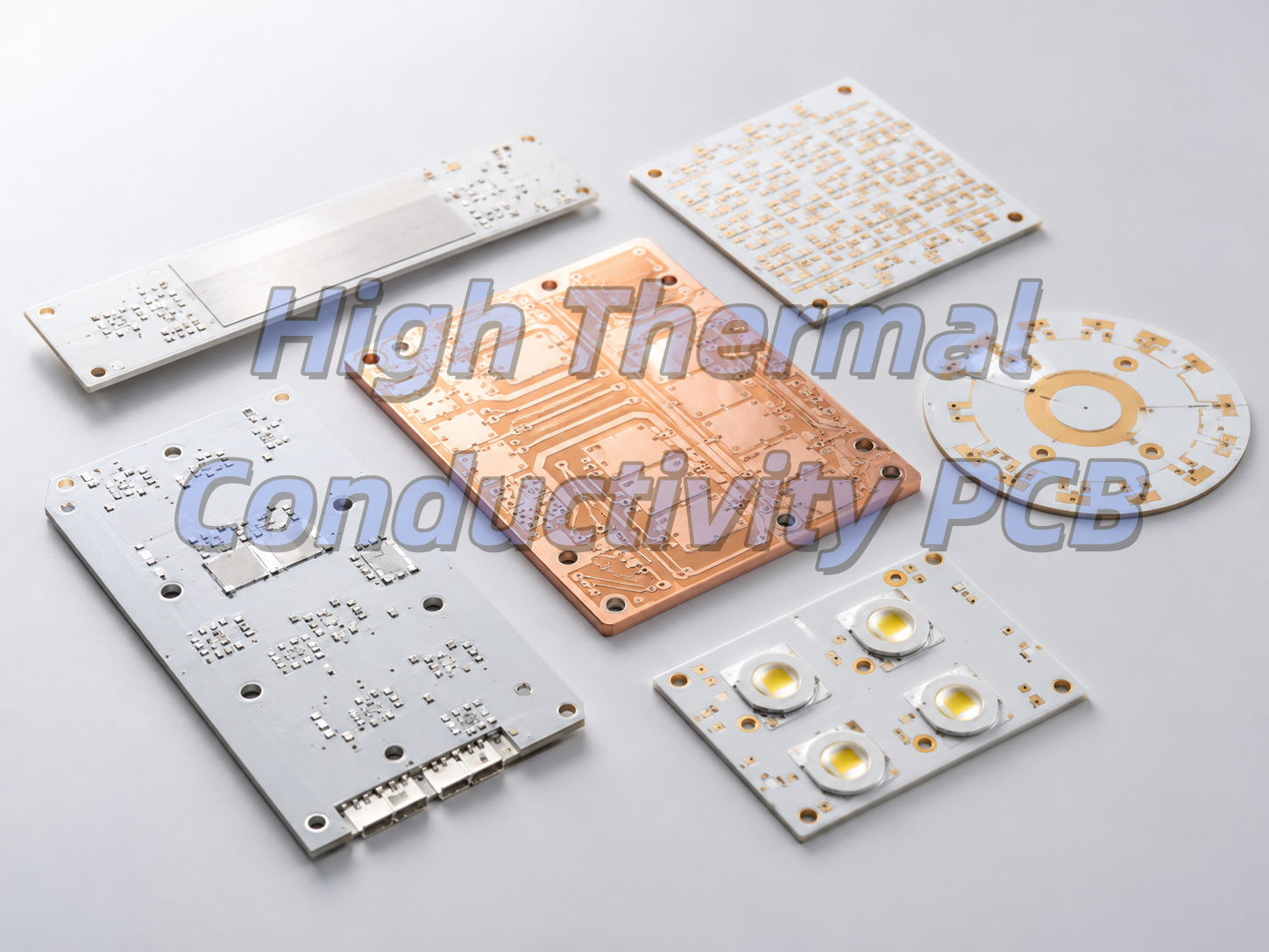
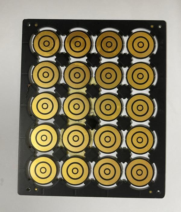
Ceramic PCB high temperature resistant substrates with keyword overlay

For PCB buyers, high temperature resistance should not be read as one simple number. A board may survive a short thermal event but still fail in long-term operation because of copper stress, solder joint fatigue, ceramic cracking, metallization adhesion, component limits, or repeated thermal cycling.

A ceramic PCB is usually chosen when the substrate must support both heat transfer and electrical reliability. Alumina, aluminum nitride, silicon nitride, thick film ceramic circuits, DBC ceramic PCB, and other ceramic substrate options each solve a different high temperature problem.

Why Choose Ceramic PCB for High Temperature Applications?

Choose ceramic PCB for high temperature applications when the board must handle heat, insulation, and dimensional stability at the same time.

Standard FR4 PCB works well for many electronic products, but its resin system limits long-term high temperature reliability. High Tg FR4 can improve heat resistance, yet it is still an organic laminate. Ceramic substrates are inorganic, so they can offer stronger temperature stability and lower thermal expansion in harsh environments.

Common high temperature ceramic PCB applications include LED modules, power electronics, semiconductor modules, automotive electronics, industrial sensors, heating control circuits, aerospace electronics, high-voltage insulation circuits, and compact assemblies where heat cannot be removed easily through a standard board stack.

PCB Option High Temperature Fit Buyer Note
FR4 PCB Good for many standard products Check Tg, Td, operating temperature, and soldering profile
High Tg FR4 Better than standard FR4 Useful when temperature is elevated but not extreme
Metal core PCB Good heat spreading Often used for LEDs and power boards, but dielectric layer matters
Ceramic PCB Strong heat resistance and insulation Best when heat, voltage, reliability, and size all matter
DBC ceramic PCB Power module and high current applications Useful when copper thickness and heat transfer are both important

What Temperature Can a Ceramic PCB Withstand?

A ceramic PCB can often tolerate much higher substrate temperatures than organic PCB laminates, but the real usable temperature depends on material, metallization, assembly, components, solder, coating, and operating time.

It is risky to ask only for “maximum temperature.” For a production design, define the continuous operating temperature, peak temperature, dwell time, temperature cycling range, heating and cooling rate, and whether the board will carry power during the high temperature condition.

EBest Circuit’s ceramic PCB page lists high-temperature resistance as a ceramic PCB process advantage and covers ceramic materials including Al2O3 and AlN. Public technical references also commonly describe ceramic substrates as suitable for high-power and high-reliability applications where FR4 temperature limits are not enough.

How Does Ceramic PCB Thermal Conductivity Affect Heat Dissipation?

Ceramic PCB thermal conductivity affects how quickly heat can move through the substrate from components to a heat sink, chassis, or surrounding structure.
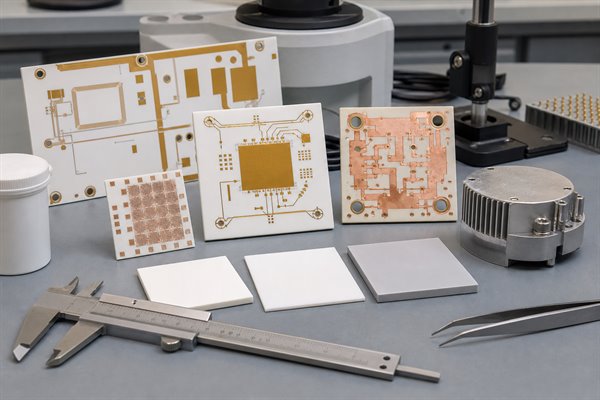
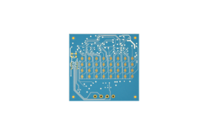
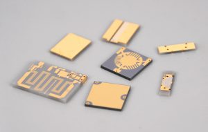
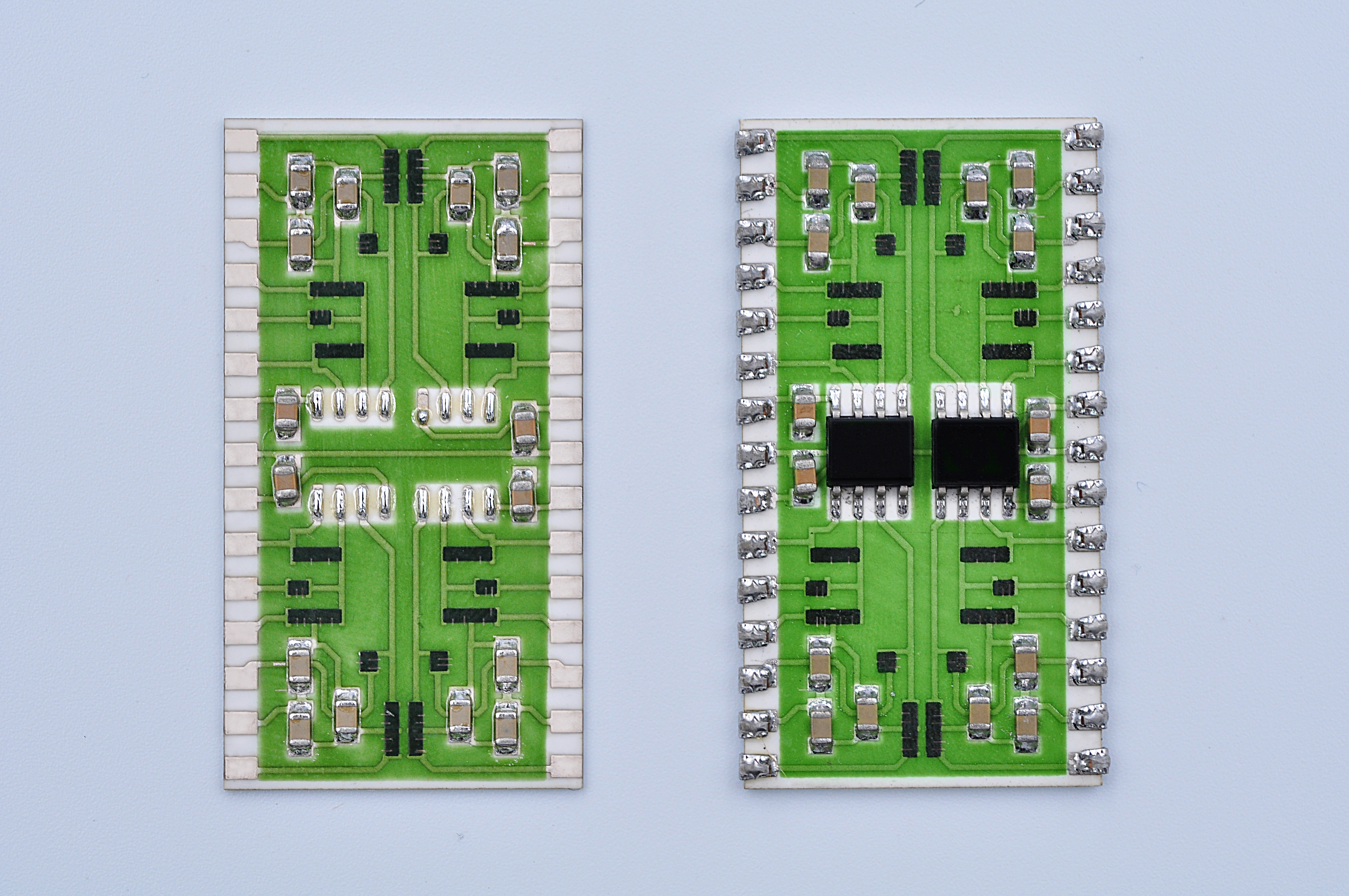
Ceramic PCB material samples for thermal conductivity and CTE review

Thermal conductivity is not the same as temperature resistance. A material can tolerate high temperature but still conduct heat poorly. Alumina ceramic PCB is often cost-effective and stable, while AlN ceramic PCB usually provides much higher thermal conductivity for stronger heat transfer. Silicon nitride may be selected when mechanical strength and thermal cycling reliability are more important.

Material Thermal Behavior Typical Decision Logic
Al2O3 / alumina Moderate ceramic thermal conductivity Cost-effective choice for many high temperature ceramic PCB projects
AlN Higher thermal conductivity Useful for high-power modules and compact heat paths
Si3N4 Good strength and thermal cycling behavior Consider when mechanical reliability is a major concern
Metal core PCB Good heat spreading through metal base Good for many LED and power applications, but not always ceramic-level insulation

For accurate selection, review the full thermal path: component package, solder layer, copper area, ceramic thickness, substrate material, interface material, heat sink, airflow, and mounting pressure.

Why Does Ceramic PCB CTE Matter in High Temperature Design?

Ceramic PCB CTE, or coefficient of thermal expansion, matters because materials expand and contract as temperature changes.

If the ceramic substrate, copper layer, solder joint, component package, and mounting structure expand at very different rates, thermal cycling can create stress. That stress may lead to cracks, delamination, solder fatigue, conductor damage, or loss of electrical reliability.

CTE matching is especially important in power modules, high-temperature sensors, automotive electronics, aerospace electronics, and products exposed to repeated heating and cooling. Buyers should provide the expected temperature cycle, not only the maximum temperature.

Al2O3 vs AlN vs Si3N4: Which Ceramic PCB Material Should You Choose?

The best ceramic PCB material depends on whether the design needs lower cost, higher thermal conductivity, stronger mechanical reliability, or better thermal cycling performance.

Al2O3 is often the first ceramic PCB material to review because it is widely used and cost-effective. AlN is usually selected when the design needs much stronger heat transfer. Si3N4 can be attractive for demanding thermal cycling or mechanical stress conditions, but availability, process route, and cost should be reviewed early.

Material Strength Limitation Best Use
Al2O3 ceramic PCB Stable, economical, mature Lower thermal conductivity than AlN General high temperature ceramic PCB, sensors, LEDs, hybrid circuits
AlN ceramic PCB High thermal conductivity Higher cost and stricter processing High-power modules, compact thermal designs, advanced LEDs
Si3N4 ceramic PCB Mechanical strength and thermal cycling potential Cost and process availability need review Demanding power electronics and reliability-focused applications

Ceramic PCB vs FR4 vs Metal Core PCB for High Temperature Use

Ceramic PCB, FR4, and metal core PCB solve different temperature and heat problems, so the best choice depends on the real operating environment.

FR4 is usually best when cost, multilayer routing, and normal operating temperatures matter most. Metal core PCB is often useful when heat spreading is needed from LEDs or power devices. Ceramic PCB becomes more attractive when the board must combine high temperature stability, insulation, compact size, and reliable heat transfer.

If the circuit has high voltage, high heat flux, repeated thermal cycling, or a small heat path, ceramic PCB should be reviewed before the layout is locked.

Which Ceramic PCB Manufacturing Process Fits High Temperature PCBs?

The manufacturing process should match the temperature, current, line width, copper thickness, and reliability requirement.

Thick film ceramic PCB is useful for hybrid circuits, sensors, and designs that need fired conductor patterns on ceramic. Thin film ceramic PCB supports finer circuit features and precision applications. DBC ceramic PCB is often used where bonded copper, power handling, and heat transfer are important.

Process Useful For High Temperature Note
Thick film Sensors, hybrid circuits, fired conductors Review conductor paste and firing system
Thin film Fine lines, precision circuits, compact modules Useful when pattern accuracy matters
DBC Power modules and higher current paths Review copper thickness, ceramic thickness, and thermal cycling
HTCC / LTCC Multilayer ceramic structures and packages Use when the design needs ceramic multilayer integration

What Design Checks Help Prevent High Temperature PCB Failure?

High temperature PCB failure is often caused by the whole assembly, not only the ceramic substrate.

  • Check continuous temperature, peak temperature, and thermal cycling range.
  • Review CTE compatibility between ceramic, copper, solder, and component packages.
  • Confirm copper thickness and conductor adhesion for the process.
  • Check solder alloy, attachment method, and component temperature ratings.
  • Review ceramic thickness, board outline, holes, slots, and edge stress.
  • Confirm whether conformal coating, potting, or enclosure materials can survive the same temperature.
  • Define inspection and reliability testing before production.

For procurement teams, a “high temperature ceramic PCB” quote should include more than Gerber files. It should include application temperature, power dissipation, operating environment, assembly requirements, and reliability expectations.

What Should You Provide for a High Temperature Ceramic PCB Quote?

A complete RFQ helps the manufacturer choose the right ceramic material, process, tolerance, copper structure, and test plan.
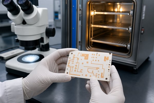
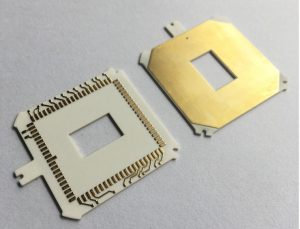
High temperature ceramic PCB inspection after thermal testing
  • Gerber files, drill file, and mechanical drawing.
  • Preferred ceramic material, such as Al2O3, AlN, or Si3N4.
  • Operating temperature, peak temperature, and temperature cycle profile.
  • Power dissipation, current load, and heat source area.
  • Copper thickness, conductor method, and surface finish.
  • Minimum line width, spacing, hole size, and tolerance requirements.
  • Assembly method, component type, solder requirement, and testing needs.
  • Prototype quantity, mass production estimate, and delivery expectation.

How EBest Circuit Supports High Temperature Ceramic PCB Projects?

EBest Circuit supports ceramic PCB manufacturing and related PCB/PCBA services for customers evaluating high temperature, high thermal conductivity, and high reliability circuit requirements.

Relevant capabilities include ceramic PCB, thick film ceramic PCB, thin film ceramic PCB, DBC ceramic PCB, FR4 PCB, metal core PCB, component sourcing, and PCB assembly. For high temperature ceramic PCB projects, the engineering review should focus on material, thermal conductivity, CTE, copper structure, process route, testing, and assembly compatibility.

If the design is still early, send the working temperature, heat source details, voltage/current requirement, and expected environment. This helps the team suggest whether Al2O3, AlN, Si3N4, DBC, thick film, thin film, FR4, or metal core PCB is the better starting point.

FAQ

Is ceramic PCB good for high temperature?

Yes. Ceramic PCB is often good for high temperature electronics because ceramic substrates provide strong insulation, stable dimensions, and better heat resistance than many organic PCB laminates. The final reliability still depends on copper, solder, components, assembly, and thermal cycling.

What is the best material for high temperature ceramic PCB?

There is no single best material for every high temperature ceramic PCB. Al2O3 is often cost-effective, AlN is useful when high thermal conductivity is needed, and Si3N4 may be considered when mechanical strength and thermal cycling reliability are major concerns.

Is thermal conductivity the same as temperature resistance?

No. Thermal conductivity describes how well heat moves through a material. Temperature resistance describes how well the material and assembly survive heat. A board can tolerate high temperature but still need better heat spreading, or conduct heat well but fail because of CTE stress or assembly limits.

Why is CTE important for ceramic PCB?

CTE matters because ceramic, copper, solder, and components expand at different rates when temperature changes. Poor CTE matching can create mechanical stress, which may cause cracking, delamination, or solder joint fatigue during thermal cycling.

Can FR4 be used for high temperature PCB?

FR4 can be used in many moderate-temperature electronics, and high Tg FR4 can improve thermal margin. For harsher environments, stronger insulation, high heat flux, or repeated thermal cycling, ceramic PCB or another high temperature substrate may be a better fit.

When should I choose metal core PCB instead of ceramic PCB?

Choose metal core PCB when heat spreading through a metal base is enough and the circuit does not require ceramic-level insulation, temperature stability, or CTE behavior. LEDs and some power boards often use metal core PCB, while ceramic PCB fits more demanding thermal and reliability cases.

What affects the cost of high temperature ceramic PCB?

Cost depends on ceramic material, substrate thickness, board size, process type, copper thickness, line width, holes, tolerance, surface finish, inspection, assembly, quantity, and lead time. AlN, fine features, tight tolerances, and special reliability testing usually increase cost.

What files are needed for a high temperature ceramic PCB quote?

Send Gerber files, drill files, drawings, stackup notes, ceramic material preference, operating temperature, thermal cycling profile, current and voltage requirements, copper thickness, surface finish, quantity, and assembly or testing requirements if needed.

Conclusion

A ceramic PCB can solve high temperature PCB problems when the design needs more than ordinary laminate heat resistance. The right choice depends on temperature profile, thermal conductivity, CTE, material type, manufacturing process, copper structure, assembly method, and quality inspection.

If you are evaluating high temperature ceramic PCB, Al2O3 PCB, AlN PCB, DBC ceramic PCB, thick film ceramic PCB, or ceramic PCB assembly, EBest Circuit can review your drawings and help choose a practical manufacturing path. Contact our engineering team for technical support and a quote at sales@bestpcbs.com.
You may also like

High Thermal Conductivity PCB: Materials & Design
Friday, May 15th, 2026

What Is a High Thermal Conductivity PCB?

High thermal conductivity PCBs are special circuit boards that move heat away from electronic parts quickly. Regular FR-4 boards only conduct 0.3-0.5 W/m·K of heat, but these boards use metal or ceramic cores to do 2-100 times better. They work as both a circuit board and a heat spreader, so you often don’t need big separate heatsinks.

Aluminum PCBs are the most popular type, making up over 85% of the market. They are cheap and work well for most power products. Other types include copper core, IMS, and ceramic PCBs for more demanding uses.

Why Is High Thermal Conductivity Important in PCB Design?

Good heat conduction makes electronics last longer and work better. A 10°C drop in component temperature can double the life of semiconductors. Bad heat dissipation makes LEDs lose 70% of their brightness in 3 years and causes power parts to fail suddenly.

In cars, thermal stability keeps safety systems working from -40°C to 125°C. Without high thermal conductivity PCBs, modern small, high-power devices like EV chargers and 5G phones would overheat and break.

What Materials Are Used in High Thermal Conductivity PCBs?

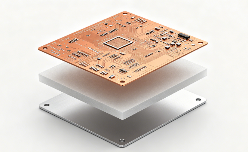
High thermal conductivity PCBs use three main layers: a copper circuit layer, a thermally conductive dielectric layer, and a core base. The dielectric layer is the most important because it causes 70-90% of the total heat resistance

High thermal conductivity PCBs layer consture

Core Material Performance Comparison

Material TypeThermal Conductivity (W/m·K)Max Temperature (°C)Cost IndexBest For
Aluminum 6061150-2051301.0General power products
Pure Copper385-4001503.5High-current modules
Alumina Ceramic18-361000+2.5Sensors and industrial parts
Aluminum Nitride150-2301000+8.0Medical and aerospace

Aluminum PCB, Copper Core PCB, IMS PCB, and Ceramic PCB: What Is the Difference?

Each type has its own strengths for different jobs. Aluminum PCBs are the cheapest and most common. Copper core PCBs conduct heat better for high-power uses. IMS PCBs have better insulation, and ceramic PCBs work in extreme temperatures.

PCB Type Comparison

PCB TypeOverall Heat Conductivity (W/m·K)Insulation VoltageCostBest Use
Aluminum PCB1-51-3 kVLowLED lights, small power supplies
Copper Core PCB3-101-3 kVMediumMotor controls, EV chargers
IMS PCB1-9Up to 5 kVMediumPower converters, car electronics
Ceramic PCB18-230>15 kV/mmHighRF devices, medical lasers

How to Choose the Right Thermal Conductivity Rating?

The right rating depends on how much power your device uses. Too low and it overheats; too high and you waste money. A simple rule: add 0.5 W/m·K for every extra 10W of power.

For small LED bulbs under 50W, 1.0-1.5 W/m·K works fine. For street lights (50-150W), use 2.0-3.0 W/m·K. For industrial converters over 300W, you need 5.0+ W/m·K or a copper core PCB.

Thermal Conductivity vs Thermal Resistance: What Should Designers Know?

Thermal conductivity is how well a material moves heat. Thermal resistance is how hard it is for heat to pass through a whole structure. Many people mix these up, which leads to bad designs.

The formula is simple: Thermal Resistance = Thickness Ă· (Conductivity × Area). This means a thin, high-conductivity layer with a big area works best. For example, a 100ÎŒm thick 3 W/m·K dielectric is the same as a 200ÎŒm thick 6 W/m·K one.

How Does Copper Thickness Affect Thermal Performance?

Thicker copper carries more current and spreads heat better. It reduces resistive heating and moves heat away from hot parts faster. Increasing copper from 1 oz to 2 oz can lower component temperature by 5-10°C.

Copper Thickness Guide

Copper WeightThickness (ÎŒm)Current per 1mm WidthTypical Use
1 oz353-5 AGeneral circuits
2 oz706-10 APower supplies, LED drivers
3 oz10510-15 AHigh-current boards
4 oz+140+15-25 A+Heavy power modules

How to Improve Heat Dissipation in PCB Layout?

Layout choices often matter more than material selection. Even the best material won’t work if heat can’t flow to the cooling system. Follow these simple rules for better results.
First, put high-power parts near the board edges or mounting holes. Use big copper pads under hot components and add copper pours around them. Use thermal vias (0.3mm diameter, 1mm apart) under exposed pads. Also, keep heat-sensitive parts at least 10mm away from hot areas.

What Applications Use High Thermal Conductivity PCBs?

High thermal conductivity PCBs are used everywhere heat is a problem. The biggest use is LED lighting, where they make bulbs last 3-5 times longer. They are also common in car electronics, power supplies, and 5G communication devices.

Other uses include motor controls, medical equipment, and aerospace parts. Any device that is small but uses a lot of power will benefit from a high thermal conductivity PCB.

How to Choose a Reliable High Thermal Conductivity PCB Manufacturer?

A good manufacturer has experience with all types of high thermal conductivity PCBs and can help with design. Look for one that uses high-quality materials and has strict quality control.

Key things to check: experience with aluminum, copper, and ceramic PCBs; ability to do thermal analysis; stable material supply; and compliance with IPC, RoHS, and REACH standards. Also, make sure they can support both prototypes and mass production.

Why Choose EBest Circuit for High Thermal Conductivity PCB Projects?

EBest Circuit offers complete high thermal conductivity PCB services, from design review to mass production. We have over 10 years of experience with all types of thermal PCBs and work with top material suppliers.

Our team can help you optimize your stackup, select the right materials, and fix thermal issues before production. We support fast prototypes and reliable mass production, so you can get your products to market quickly.

FAQs About High Thermal Conductivity PCB

Q1: Can high thermal conductivity PCBs be multilayer?

A1: Yes, but they are more expensive than single-layer ones. Most designs use 1-2 layers, with 4+ layers only for special high-density needs.

Q2: How much more do they cost than FR-4?

A2: They usually cost 2-3 times more than FR-4. But they often eliminate the need for separate heatsinks, saving total system cost.

Q3: What is the maximum voltage they can handle?

A3: Standard aluminum PCBs handle 1-3kV. Special high-voltage designs can go up to 5kV, and ceramic PCBs offer even higher insulation.

Q4: Can aluminum PCBs be bent?

A4: Yes, 5052 aluminum alloy bends well. This is useful for curved LED lights and other custom shapes.

Q5: How do I test the actual thermal conductivity?

A5: Ask your manufacturer for laser flash analysis (LFA) test data. Datasheet values are often higher than real-world performance.

You may also like

What is the thermal conductivity of copper practical?
Wednesday, September 25th, 2024

In the vast field of materials science, copper occupies an important position with its excellent performance. Among them, the thermal conductivity of copper is particularly eye-catching, becoming the preferred material for heat conduction in many fields. Copper plays an important role in electronic equipment, heat exchangers, construction and other fields.

What is the thermal conductivity value for copper?

The thermal conductivity of copper is about 401W/m·K. ‌

What is the thermal conductivity value for copper?

The thermal conductivity refers to the heat transferred through 1 square meter of area in 1 second under stable heat transfer conditions, with a temperature difference of 1 degree (K, ℃) on both sides of a 1 meter thick material. The unit is watt/meter·degree (W/(m·K)).

The thermal conductivity is a parameter to measure the thermal conductivity of a material. The larger the value, the better the thermal conductivity. Due to its high thermal conductivity, copper is often used to make radiators, heat conductors and other applications that require efficient heat transfer.

What is the thermal conductivity of copper at 25 C?

The thermal conductivity of copper is affected by many factors. On the one hand, temperature is an important influencing factor. Generally speaking, the thermal conductivity of copper decreases with increasing temperature.

At 25℃, the thermal conductivity of copper is about 401W/m.K, and at 100℃, the thermal conductivity of copper is 377W/m・K.

How do you measure thermal conductivity of copper?

The thermal conductivity of copper is usually measured by the steady-state method. ‌

The steady-state method is a classic method for measuring the thermal conductivity of thermal insulation materials. It uses the equilibrium state in which the heat transfer rate is equal to the heat dissipation rate during stable heat transfer.

This method has a simple and clear principle and high accuracy. Although the measurement time is long and the environmental conditions are high, it is suitable for measuring thermal conductivity materials at medium temperatures, especially for low thermal conductivity materials such as rock, plastic, rubber, glass, and thermal insulation materials.

In the steady-state method, commonly used methods include heat flow method, protected heat flow method, and protected hot plate method. The basic principles of these methods are similar, but some standards are formulated for different thermal insulation materials, and the test results are similar.

What metal has the highest thermal conductivity?

Silver has the highest thermal conductivity.

Among metals, silver has a thermal conductivity of 411W/(m·K), which is the highest value among all metals. This property of silver makes it the metal with the best thermal conductivity.

In contrast, copper has a thermal conductivity of 401W/(m·K), which is also very high, but still slightly lower than silver. Other metals such as gold and aluminum have thermal conductivities of 315W/(m·K) and 237W/(m·K), respectively, which are lower than silver and copper. Therefore, from the perspective of thermal conductivity, silver is undoubtedly the metal with the best thermal conductivity.

In addition, although the thermal conductivity of copper is also very high, reaching 401W/(m·K), second only to silver, among pure metals, the thermal conductivity of silver is still the highest. However, in practical applications, copper is widely used because of its good conductivity and relatively low cost.

Which metal is the poorest conductor of heat?

The metal with the worst thermal conductivity is iron. ‌

Among metal materials, the thermal conductivity of iron is 0.163, while that of copper and silver is, and that of aluminum is 0.5. These data indicate that the thermal conductivity of iron is significantly lower than that of other common metals. Therefore, it can be concluded that iron is the metal with the worst thermal conductivity‌.

Why copper has highest thermal conductivity?

Copper has the highest thermal conductivity‌, mainly because of its unique physical and chemical properties. The superior thermal conductivity of copper is mainly attributed to its crystal structure and electronic properties.

What is the thermal conductivity value for copper?

Copper is a metal with good electrical and thermal conductivity, which is due to the presence of a large number of free electrons in the crystals of copper. These free electrons can effectively transfer heat when colliding with metal cations in the crystal, making copper extremely thermally conductive.

The thermal conductivity of copper is about 400 W/m·K, which means that copper transfers much more heat per unit time than most other materials. The high thermal conductivity allows copper to quickly transfer heat away, with efficient heat dissipation.

What happens to copper when it is heated?

When copper is heated, its volume increases, its mass remains unchanged, and its density decreases. ‌

When copper is heated, its volume increases due to the property of thermal expansion and contraction. This is because when the copper block is heated, the distance between atoms increases, resulting in an increase in volume. At the same time, the mass of copper is a property of matter, which is only related to the amount of matter contained, and has nothing to do with the position, state, shape, and temperature of the object. Therefore, the mass of copper remains unchanged after heating.

In addition, when copper is heated in the air, if it reacts with oxygen, black copper oxide (CuO) will be generated on the surface. This chemical change will cause the color of copper to change from red to black.

In summary, when copper is heated, not only will its volume increase, its mass remain unchanged, and its density decrease, but it will also react with oxygen to generate copper oxide when heated in the air, resulting in a change in surface color.

Why does copper turn green?

Copper turns green because it is oxidized in the air to form copper rust. The main component of this copper rust is basic copper carbonate, which is green in color. ‌

Copper will be oxidized in the air to form copper rust. This rusting process is the result of a combination of factors, including the reaction of copper with oxygen, water vapor and carbon dioxide in the air.

Specifically, when copper is exposed to oxygen, water and carbon dioxide in humid air for a long time, a chemical reaction will occur to generate basic copper carbonate (Cu2(OH)2CO3), a green inorganic compound, so a green rust layer will form on the copper surface.

This process not only occurs on the surface of copper, but also because the main component of copper rust is basic copper carbonate, the color of copper rust is green, which makes the appearance of copper products appear green.

Copper has become the preferred material for heat conduction in many fields due to its high thermal conductivity, good processing performance and stable thermal conductivity. With the continuous advancement of science and technology, it is believed that copper will continue to play an important role in future development.

You may also like

Why Thermal Conductivity Layer is Important in Aluminum PCB?
Tuesday, January 2nd, 2024

In the aluminum PCB design, people always mention the thermal conductivity value. Do you know what about thermal conductivity and you know what is the role of this layer in the aluminum core circuit board? Welcome to keep reading if you are interested in it.

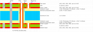
(1_layer_aluminum_pcb)

What is thermal conductivity?

Thermal conductivity is a physical value signifies the capacity of a material to allow heat flow per unit area through it in a unit of time. A higher thermal conductivity indicates better heat conduction for the material. In the field of heat generation and thermal management products, thermal conductivity is a crucial parameter as it relates to the product’s heat dissipation capability and stability. In the structure of aluminum, the thermal conductivity layer is always stand between the copper circuit layer and base material, so that the heat generated by product can be transfer quickly to outside.

(Stack_up_for_1_layer_aluminum_PCB)

Significance of Thermal Conductivity in Aluminum PCBs

Aluminum substrates are commonly used materials in heat dissipation and thermal management products. Their thermal conductivity is a vital element evaluated heat dissipation properties typically in W/m·K. It can be understood as the material’s heat transfer rate, i.e., the amount of heat conducted per unit time. Specifically, assuming the same amount of heat is conducted in aluminum substrates and other materials, the conduction rate of aluminum substrate will be faster over a certain period. This implies that aluminum substrates can transfer heat more quickly from the heat source to the external environment, achieving efficient heat dissipation.

Impact of Thermal Conductivity on Heat Dissipation Products

The primary function of thermal management products is to dissipate heat. How does thermal conductivity specifically affect them? Let us dive into from below aspects:

1. Thermal Conductivity Value

A higher thermal conductivity leads to better heat dissipation capability, as it can achieve faster transfer of heat from the heat source to the environment. Therefore, thermal conductivity of aluminum substrates plays a crucial role in the heat dissipation products, such as the LED lights, industrial power devices, automotives. At EBest Circuit (Best Technology), the thermal conductivity we used for aluminum PCB always is range from 1.0 to 3.0W (thickness=75-200um). Different thermal conductivity value has its own thickness.

2. Product Stability

The stability of a product also depends on its thermal conductivity. According to our 17+ manufacturing experience, insufficient thermal conductivity in heat dissipation products may result in overheating during prolonged operation, potentially shortening the product’s lifespan. Let me take a simple example, assume your mobile phone is under long time playing games, then it will generate many heats, finally causing the overheating phenomenon. And this will shorten its lifecycle if you always do like that.

(Single_sided_4_layer_aluminum_PCB)

When it comes to thermal conductivity selection, there is a big misunderstanding is that some may believe that higher thermal conductivity in aluminum substrates is always better. However, this is not entirely accurate. While higher thermal conductivity is generally favorable, it does not mean that aluminum substrates with the highest thermal conductivity are suitable for all heat dissipation applications. In specific use cases, it is essential to choose the appropriate thermal conductivity for aluminum substrates based on actual requirements to achieve the optimal heat dissipation effect.

By the way, if you want to choose higher thermal conductivity value, ceramic PCB is a better choice, which can achieve 24W or more. It mainly depends on its ceramic substrate material, like the Al2O3 thermal conductivity value is around 24W~28W/m-K, while AlN enable to reach 150W~240W/m-K.

Conclusion

All in all, to ensure optimal heat dissipation effects and stability, it is crucial to choose the right thermal conductivity for aluminum substrates based on actual needs. The careful consideration of thermal conductivity values in aluminum PCBs is integral to the longevity and performance of heat dissipation products, emphasizing the importance of informed selection in the pursuit of effective thermal management.

EBest Circuit (Best Technology) is an expert in metal core PCB manufacturing, we have strong R&D team and full-experienced employs that can provide with you the best metal core PCB solution. Welcome to contact us at sales@bestpcbs.com if you want to know more.

You may also like