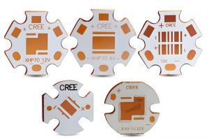
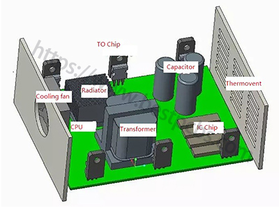
Heavy copper PCB manufacturers in USA range from specialists in very thick conductors to suppliers that fabricate, assemble, and test complete boards. Choosing between them requires matching copper distribution, holes, and the complete layer stack to a process available at the required US site.
A 20 oz outer-layer power board needs a different manufacturing process from a 4 oz prototype supplied with components assembled. Copper capability determines which suppliers can build the board; engineering support, assembly services, and the prototype-to-production route determine which can deliver the complete order.
Top 15 Heavy Copper PCB Manufacturers in USA Compared
Amitron and Pro-Tech offer specialized thick-copper processes, while Cirexx, PNC, Sierra, and Gorilla combine fabrication with assembly services. Larger networks such as FTG, Sanmina, and TTM offer multiple production locations, making the selected factory as important as the company’s overall capability.
| Manufacturer | Heavy Copper Capability | Advantages | Lead time | Services |
|---|---|---|---|---|
| 1. AmitronElk Grove Village, IL | 20+ oz finished copper | Mixed copper weights within one layer | Quoted per heavy-copper order | PCB fabrication |
| 2. Pro-Tech Interconnect SolutionsChaska, MN | Extreme copper: above 20 to 120 oz | Local copper buildup for power paths and holes | Quoted per heavy-copper order | PCB fabrication; selective plating |
| 3. AdvancedPCBMultiple US sites | Up to 4 oz inner; 20 oz outer | Mixed-weight layers with design support | Quoted per heavy-copper order | PCB design support; fabrication |
| 4. Saturn ElectronicsRomulus, MI | Up to 20 oz | US double-sided and multilayer boards | Quoted per heavy-copper order | Bare PCB fabrication |
| 5. Excello CircuitsAnaheim, CA | 0.5–4 oz inner; 1–20 oz outer | Prototype and repeat-build support | Quoted per heavy-copper order | Prototype and production PCB fabrication |
| 6. Cirexx InternationalUS in-house PCB site | Up to 4 oz inner; 6 oz outer | Layout, PCB assembly and test | Quoted per heavy-copper order | PCB layout; fabrication; assembly; testing |
| 7. PNC Inc.Nutley, NJ | 0.5–8 oz published range | Design and assembly at one US site | Quoted per heavy-copper order | PCB design; fabrication; assembly |
| 8. Sierra CircuitsUS PCB sites | Advanced: up to 6 oz inner and finished outer | Advanced boards with assembly | Quoted per heavy-copper order | PCB fabrication; component sourcing; assembly |
| 9. Gorilla CircuitsSan Jose, CA | 4 oz stated maximum | In-house PCB, assembly and test | Quoted per heavy-copper order | PCB fabrication; assembly; testing |
| 10. Bay Area CircuitsSilicon Valley, CA | Up to 4 oz inner; 5 oz outer, finished | Local and offshore PCB options | Quoted per heavy-copper order | PCB fabrication; offshore sourcing |
| 11. Omega Circuits & EngineeringNew Brunswick, NJ | Up to 9 oz | Metal-based boards and heat sinks | Quoted per heavy-copper order | PCB fabrication; assembly with customer-supplied parts |
| 12. American Standard CircuitsWest Chicago, IL | Heavy copper; confirm layer limits | Heavy copper and thermal board options | Quoted per heavy-copper order | PCB fabrication; global sourcing |
| 13. FTG CircuitsCA, VA, MA and MN | Heavy copper; confirm site limits | US sites with varied PCB processes | Quoted per heavy-copper order | PCB fabrication; new-product introduction |
| 14. SanminaSan Jose, CA; other US sites | Above 6 oz group offering; confirm US site | US new-product builds and global supply | Quoted per heavy-copper order | PCB fabrication; new-product introduction |
| 15. TTM TechnologiesMultiple US sites; global network | 2–12 oz auto offering; confirm US site | Auto power boards and multiple sites | Quoted per heavy-copper order | PCB fabrication |
| Manufacturer | Heavy Copper Capability | Advantages |
|---|---|---|
| 1. AmitronElk Grove Village, IL | 20+ oz finished copper | Mixed copper weights within one layer |
| 2. Pro-Tech Interconnect SolutionsChaska, MN | Extreme copper: above 20 to 120 oz | Local copper buildup for power paths and holes |
| 3. AdvancedPCBMultiple US sites | Up to 4 oz inner; 20 oz outer | Mixed-weight layers with design support |
| 4. Saturn ElectronicsRomulus, MI | Up to 20 oz | US double-sided and multilayer boards |
| 5. Excello CircuitsAnaheim, CA | 0.5–4 oz inner; 1–20 oz outer | Prototype and repeat-build support |
| 6. Cirexx InternationalUS in-house PCB site | Up to 4 oz inner; 6 oz outer | Layout, PCB assembly and test |
| 7. PNC Inc.Nutley, NJ | 0.5–8 oz published range | Design and assembly at one US site |
| 8. Sierra CircuitsUS PCB sites | Advanced: up to 6 oz inner and finished outer | Advanced boards with assembly |
| 9. Gorilla CircuitsSan Jose, CA | 4 oz stated maximum | In-house PCB, assembly and test |
| 10. Bay Area CircuitsSilicon Valley, CA | Up to 4 oz inner; 5 oz outer, finished | Local and offshore PCB options |
| 11. Omega Circuits & EngineeringNew Brunswick, NJ | Up to 9 oz | Metal-based boards and heat sinks |
| 12. American Standard CircuitsWest Chicago, IL | Heavy copper; confirm layer limits | Heavy copper and thermal board options |
| 13. FTG CircuitsCA, VA, MA and MN | Heavy copper; confirm site limits | US sites with varied PCB processes |
| 14. SanminaSan Jose, CA; other US sites | Above 6 oz group offering; confirm US site | US new-product builds and global supply |
| 15. TTM TechnologiesMultiple US sites; global network | 2–12 oz auto offering; confirm US site | Auto power boards and multiple sites |
| Manufacturer | Lead time | Services |
|---|---|---|
| 1. AmitronElk Grove Village, IL | Quoted per heavy-copper order | PCB fabrication |
| 2. Pro-Tech Interconnect SolutionsChaska, MN | Quoted per heavy-copper order | PCB fabrication; selective plating |
| 3. AdvancedPCBMultiple US sites | Quoted per heavy-copper order | PCB design support; fabrication |
| 4. Saturn ElectronicsRomulus, MI | Quoted per heavy-copper order | Bare PCB fabrication |
| 5. Excello CircuitsAnaheim, CA | Quoted per heavy-copper order | Prototype and production PCB fabrication |
| 6. Cirexx InternationalUS in-house PCB site | Quoted per heavy-copper order | PCB layout; fabrication; assembly; testing |
| 7. PNC Inc.Nutley, NJ | Quoted per heavy-copper order | PCB design; fabrication; assembly |
| 8. Sierra CircuitsUS PCB sites | Quoted per heavy-copper order | PCB fabrication; component sourcing; assembly |
| 9. Gorilla CircuitsSan Jose, CA | Quoted per heavy-copper order | PCB fabrication; assembly; testing |
| 10. Bay Area CircuitsSilicon Valley, CA | Quoted per heavy-copper order | PCB fabrication; offshore sourcing |
| 11. Omega Circuits & EngineeringNew Brunswick, NJ | Quoted per heavy-copper order | PCB fabrication; assembly with customer-supplied parts |
| 12. American Standard CircuitsWest Chicago, IL | Quoted per heavy-copper order | PCB fabrication; global sourcing |
| 13. FTG CircuitsCA, VA, MA and MN | Quoted per heavy-copper order | PCB fabrication; new-product introduction |
| 14. SanminaSan Jose, CA; other US sites | Quoted per heavy-copper order | PCB fabrication; new-product introduction |
| 15. TTM TechnologiesMultiple US sites; global network | Quoted per heavy-copper order | PCB fabrication |
How Do You Choose a Heavy Copper PCB Manufacturer?
The right manufacturer must support the copper distribution and geometry in your drawing, then deliver the required bare board or assembly at the intended volume. A supplier’s maximum copper weight is only one part of that decision. Use the design and build requirements to make these five choices:
- Match copper to the correct layers. List the required finished copper on every layer before screening suppliers. If a design needs 6 oz internally, a published 20 oz outer-layer capability with a 4 oz internal limit is not a suitable match. Request a custom-process review or select a supplier whose stated internal range covers the design.
- Choose uniform, mixed-layer, or selective copper construction. Thick power traces and fine control routing may need different copper weights across layers or localized buildup within one layer. Show those regions on the drawing and ask whether the supplier’s etching, plating, and lamination process supports the transitions without widening the board or rerouting critical features.
- Review current-carrying connections and heat removal. Send the terminal, hole, and heat-sink interface details with the copper specification. A thick trace still needs suitable connections and a path for dissipating heat. Choose a manufacturer that can review these features together and identify the geometry or assembly changes required before fabrication.
- Decide whether to buy bare boards or a complete assembly. A fabrication specialist can suit a design with an established assembly partner. For a populated prototype, compare suppliers that can coordinate board fabrication, component supply, soldering, and the required tests; confirm which of those services are included in the quotation.
- Match the supplier to the next production stage. Request prices and schedules for both the initial lot and expected repeat quantity. Identify changes in factory, material, or process between those stages. If domestic fabrication or a specific qualification is required, retain only suppliers able to meet it for both builds.
1. Amitron
Amitron’s main distinction is combining very thick conductors with lighter circuitry. The Illinois manufacturer publishes 20+ oz finished copper and a process called Laminated Deposition. It also describes multiple copper weights on the same layer, making it a candidate when a power path and its control circuitry need to share one board.
For a mixed-weight design, request the permitted transition geometry, conductor spacing, and solder-mask coverage at each copper height. Specify hole-wall copper separately: the surface-copper rating does not define the plating inside a current-carrying hole.
2. Pro-Tech Interconnect Solutions
Pro-Tech’s Chaska operation deserves consideration when copper must be concentrated in selected features. Its heavy and extreme copper offering extends above 20 oz to 120 oz for extreme constructions. Selective plating also allows localized buildup on conductors and plated-through holes, rather than requiring one copper height throughout the design.
Send a drawing of the thickened regions and their connections to lighter circuitry. Ask for achievable height, coplanarity, spacing, and hole-plating limits for that construction. The extreme-copper figure is not a blanket specification for every multilayer or selective feature.
3. AdvancedPCB
AdvancedPCB is an option for multilayers that combine thick external power conductors with lighter internal routing. Its custom capability table lists up to 4 oz inner copper and 20 oz outer copper, alongside mixed-weight stackups and design support. APCT, Advanced Circuits, and San Diego PCB Design now sit under this combined business.
Have the proposed factory approve copper weights, layer count, holes, and spacing together. A design requiring 20 oz on internal layers is not covered by the published 20 oz outer-layer figure; that distinction can eliminate an unsuitable quote before layout is finalized.
4. Saturn Electronics
Saturn is a Romulus, Michigan bare-board fabricator with double-sided and multilayer capability up to 20 oz. It is a direct candidate for domestic high-copper fabrication when component sourcing and assembly are being handled separately.
Check the required qualification against the actual copper construction. Saturn’s page distinguishes its stated UL scope of up to 6 oz on inner and outer layers from its fabrication capability up to 20 oz. Those are different claims; request current construction-specific documentation if qualification is required.
5. Excello Circuits
Excello’s Anaheim operation combines prototype and production fabrication with a clearly divided copper range: 0.5–4 oz internally and 1–20 oz externally. That makes it a candidate for thick outer-layer power boards expected to move from development batches to repeat orders.
Obtain a proposed production stackup with the prototype quote. Ask whether copper geometry, materials, and manufacturing site will remain the same at the intended volume, and have any production-driven design changes identified before approving the first build.
6. Cirexx International
Cirexx combines in-house US fabrication with layout, assembly, and testing. Its stated limits of 4 oz inner and 6 oz outer copper place it among the integrated options for a populated power board rather than a 20 oz bare-board requirement.
Define the assembly and test deliverables, including high-current terminals, programming, and functional checks where needed. Request review of soldering access and thermal demands around heavy-copper connections; fabrication acceptance alone does not settle the assembly process.
7. PNC Inc.
PNC brings design, fabrication, and assembly into its Nutley, New Jersey facility. Its published copper range is 0.5–8 oz. The single-site model is a useful distinction when fabrication and assembly questions need to be resolved together during power-board development.
Ask which inner- and outer-layer combinations the 8 oz figure covers. Use the approved layer-by-layer stackup as the basis for the combined fabrication and assembly quote.
8. Sierra Circuits
Sierra offers US PCB fabrication with component procurement and assembly options. Its current product comparison assigns up to 6 oz inner copper and 6 oz finished outer copper to the Advanced PCB service. A heavy-copper prototype therefore needs a quote for that service rather than the standard online product.
Request the advanced construction explicitly. The same comparison lists lighter copper for standard and bundled quick-turn products, so a general prototype price or advertised turnaround does not establish the price or schedule for a 6 oz assembled board.
9. Gorilla Circuits
Gorilla pairs PCB fabrication with assembly and test operations in San Jose. Its published FAQ states a maximum of 4 oz. It is a candidate for integrated 4 oz builds where the fabrication and assembly route is as important as the copper rating.
Establish whether repeat orders will use the in-house facilities or a fabrication partner; Gorilla also describes high-volume partner options. For a US-only order, have both the prototype and production quotes name the approved fabrication location.
10. Bay Area Circuits
Bay Area Circuits’ advanced matrix specifies finished copper up to 4 oz internally and 5 oz externally. Those limits refer to the completed conductor, including the finished-copper requirement used in the fabrication drawing. It offers both local fabrication and offshore sourcing.
Name the required manufacturing route in the RFQ and compare the resulting price and schedule on that basis. A local fabrication requirement should remain explicit when moving from a prototype order to a larger batch.
11. Omega Circuits & Engineering
Omega publishes American-built PCBs from New Brunswick, New Jersey and heavy-copper capability up to 9 oz. Metal-based boards and custom heat sinks broaden the discussion when the design needs a defined heat-removal path as well as substantial copper conductors. Assembly is also offered, generally with customer-supplied components.
Provide the mechanical thermal interface and identify whether heavy copper, a metal-based construction, or a separate heat sink is required. These portfolio options are not automatically combined in one board. For assembly, agree on component supply and responsibility for missing or unsuitable parts.
12. American Standard Circuits
American Standard Circuits manufactures in West Chicago and offers heavy copper within a portfolio that includes metal-backed, RF, flex, and rigid-flex technologies. It is worth evaluating when the board architecture is still being selected to balance electrical and thermal requirements.
Request a numerical copper limit and accepted geometry for the proposed stackup before including ASC in a copper-range comparison. Also distinguish West Chicago fabrication from the company’s global sourcing options before comparing its offer with a domestic-only quote.
13. FTG Circuits
FTG’s US locations include Chatsworth, Fredericksburg, Haverhill, and Minnetonka. Its group portfolio includes heavy copper, thermal management, RF, and rigid-flex technologies. The network is relevant when a program needs several specialized board types and a coordinated supplier relationship.
Route the heavy-copper drawing to a named facility and obtain that site’s copper and geometry limits. Group-level technology coverage does not mean every plant supports every construction, nor that separate RF, rigid-flex, and heavy-copper capabilities can be combined without a design review.
14. Sanmina
Sanmina combines domestic PCB fabrication and new-product introduction with an international production network. Its San Jose fabrication material includes heavy copper; its group technology material describes constructions above 6 oz. The sourcing question is how to carry an approved early build into the intended production route.
Identify the factory offering the required copper weight and the factory planned for repeat orders. If those differ, include transfer qualification, approved material substitutions, and pilot-build acceptance in the plan. The group-level above-6-oz figure alone does not establish a US plant’s limits.
15. TTM Technologies
TTM’s automotive portfolio lists 2–12 oz copper within a global network that includes multiple US fabrication sites. It is a candidate for automotive power programs where supplier qualification and continuing production support matter alongside the board technology.
Ask TTM to identify the plant supporting the specified automotive construction, then confirm whether it satisfies the US fabrication requirement. The portfolio’s 12 oz maximum is not evidence of 12 oz availability at every domestic site; approval should follow the selected plant and stackup.
Which Manufacturers Match Different Heavy Copper PCB Requirements?
Heavy-copper projects place different demands on a supplier: a very thick power conductor needs a suitable copper process, a populated prototype needs assembly coordination, and a heat-limited design needs a defined thermal interface. The supplier groups below connect those requirements to the capabilities described in the company profiles, with the layer or factory details that need confirmation.
- Around 20 oz or heavier: compare Amitron, Saturn, AdvancedPCB, and Excello for their stated 20 oz-class offerings. AdvancedPCB and Excello specify that figure for outer layers. Pro-Tech is another candidate for extreme constructions beyond 20 oz; its process needs a separate geometry review.
- Selective or mixed-weight copper: examine Pro-Tech for localized plating and Amitron for multiple weights on the same layer. AdvancedPCB describes mixed-weight multilayer stackups. Different weights across layers and different heights within a layer are separate construction requests.
- A fabricated and assembled board: compare Cirexx, PNC, Sierra, and Gorilla within their copper ranges. Distinguish component procurement, assembly, and test in the quote; specify the included parts, assembly work, and tests as separate deliverables.
- A defined heat-removal interface: include Omega and American Standard Circuits when evaluating metal-based or heat-sink-related alternatives alongside heavy copper. Select the structure against the actual thermal path, rather than assuming the thickest conductor solves every hot spot.
- Multiple plants or a production transfer: examine FTG, Sanmina, and TTM at the facility level. A network can offer sourcing options, but the chosen copper construction and US production requirement must survive any proposed site change.
How Should You Compare Heavy Copper PCB Quotes?
Heavy-copper quotations can differ in finished copper, conductor spacing, hole plating, and test scope even when they use the same copper-weight label. Send each supplier the same drawing revision and request a written response against the technical requirements below. Once the construction is aligned, compare total lot price, tooling, included testing, assembly, freight, and delivery date at the same quantity.
| Specification | Equivalent quote requirement |
|---|---|
| Finished copper by layer | The same completed conductor requirement and tolerance on each named layer. Starting foil weight and added plating must not be mistaken for interchangeable finished-copper specifications. |
| Geometry at that copper weight | Accepted conductor width, spacing, pads, and copper-height transitions for the proposed process. A general fine-line minimum is not proof of the same spacing at maximum copper weight. |
| PTH and terminal connections | Separate hole-wall plating and finished-hole requirements, including current-carrying terminal holes. Agree on how plating thickness will be verified; thick surface copper does not specify the barrel. |
| Complete layer stack | The same layer count, copper distribution, dielectric construction, and finished thickness. Maximum layer count and maximum copper weight must be supported together, not taken independently from a capability table. |
| Reliability acceptance | Agreed inspection and electrical-test records. Where thermal cycling is required, define samples, conditions, measurements, and pass/fail criteria; a general quality certificate does not supply these details. |
| Prototype and production route | The approved factory, process, and change-control requirements for each build stage. Separate one-time qualification costs from recurring board cost so the volume comparison remains meaningful. |
How Can You Verify US Heavy Copper PCB Fabrication?
A domestic-production requirement applies to the factory making the bare board, including any subcontracted work covered by that requirement. Suppliers with US sales, assembly, or multiple manufacturing sites may offer more than one production route. Establish the actual route before placing the order, then use quotation, process, and delivery records to verify it through these six checks:
- Identify the actual fabrication site. Ask for the legal manufacturer and factory address on the quotation. Separate bare-board fabrication from sales, component sourcing, and assembly. If a broker or group sales team handles the order, obtain the producing site’s identity before approving it.
- Confirm that site’s heavy-copper capability. Submit the proposed stackup and ask the factory to accept the required copper by layer, conductor spacing, hole-wall plating, and finished thickness together. A group capability page is insufficient when its thickest-copper process belongs to another location.
- Clarify subcontracted processes. Ask which operations the selected site performs and whether plating, special finishes, testing, or other work goes to an outside provider. Obtain the proposed locations and responsibilities for the operations that affect your sourcing requirements.
- Check the relevant records. Where the order requires a quality-system certificate or construction qualification, verify the named facility, scope, and current validity. Request sample inspection or test-report formats to establish the delivery evidence; agree which reports must accompany each delivered lot.
- Separate prototype and production routes. Confirm the site, materials, and process planned for both stages. If volume orders may move to a partner or offshore factory, resolve that proposal before prototype approval and define the additional qualification needed for a transfer.
- Bind the approved route to the order. Put the agreed fabrication location and change-approval requirements in the purchase documents. At delivery, match the lot identification, manufacturer records, and agreed inspection reports to that route. Investigate discrepancies before accepting a changed source.
Heavy Copper PCB RFQ Checklist
A heavy-copper RFQ needs enough information to price the board, review its manufacturability, and define the delivery scope. Fabrication files describe the layout, while operating conditions, test requirements, and build quantities identify work that may change the construction or quotation. Assemble the following information into one revision-controlled package:
- Board and copper definition: Gerber or ODB++, drill files, fabrication drawing, stackup, material, and finished thickness. Specify finished copper and tolerance by layer; show selective buildup areas and any required starting foil separately. Mark a provisional stackup clearly and request written approval of proposed changes.
- Current and temperature limits: identify high-current paths, continuous or pulsed load, duty cycle, allowable voltage drop, ambient conditions, and maximum permitted temperature rise. These inputs support review of the proposed conductor geometry; copper weight alone is not a current rating.
- Critical geometry and connections: highlight minimum conductor width/spacing, copper-height transitions, high-current terminal pads, finished-hole sizes, and hole-wall plating requirements. Include connector or busbar interface drawings where relevant.
- Acceptance and quantities: define electrical testing, inspection records, and any thermal-cycling or product-specific qualification requirements. State prototype, pilot, and production quantities, target dates, and the required fabrication country.
- Assembly scope: include the BOM, placement data, assembly drawing, and component-sourcing responsibilities. Flag power terminals, heat sinks, programming, and functional-test requirements that must be included in the assembled-board quote.
How Can EBest Circuit Support Your Heavy Copper PCB Project?
EBest Circuit combines heavy copper PCB manufacturing, component sourcing, and PCB assembly for projects that permit manufacturing in China. Its services can help you resolve board requirements before ordering and coordinate fabrication with the parts and assembly work needed for delivery. The practical benefits are:
- Identify manufacturing issues before committing to a build. A free DFM review gives you an opportunity to resolve copper spacing, holes, and construction questions before fabrication. Submit the stackup and design files early so proposed changes can be assessed before components and assembly plans depend on the board revision.
- Translate the heavy-copper design into a clear fabrication requirement. Review finished copper by layer, critical connections, and any selective buildup with the board manufacturer. An agreed construction gives your engineering and purchasing teams a common basis for approving the quotation and checking whether a proposed change is acceptable.
- Reduce handoffs between fabrication and assembly. PCB manufacturing and assembly services let you discuss the bare board, power terminals, heat sinks, and component placement within one order scope. This helps bring soldering and assembly-access requirements into the board review before the design is released.
- Coordinate component purchasing with the assembly order. Component-sourcing support can reduce the separate purchasing work needed for a populated board. Provide the BOM, exact part numbers, and acceptable alternatives; confirm proposed substitutions and their effect on availability before approving procurement.
- Plan prototype and repeat orders together. Discuss the initial quantity, expected production volume, and target delivery dates at the quotation stage. Comparing both stages helps you identify material, construction, or sourcing changes that need approval before a successful prototype becomes a repeat order.
- Make the complete order cost easier to evaluate. Define fabrication, components, assembly, any requested testing, and shipping in the quotation. A clear scope helps purchasing compare the same deliverable across suppliers and identify omitted work before issuing the order; copper weight alone cannot establish the total assembled-board cost.
FAQs About Heavy Copper PCB Manufacturers in USA
Q1: Is there a standard minimum order for a heavy copper PCB prototype?
A1: Minimum quantities and lot charges vary by supplier and construction. Request the number of boards you need plus a separate price for the planned production quantity. A prototype lot price includes setup work and is not a reliable volume unit-price estimate.
Q2: How much do heavy copper PCBs cost in the USA?
A2: There is no useful universal price without board data and quantity. Copper distribution, layer stack, board dimensions, geometry, materials, inspection, and schedule affect the offer. Compare total lot prices for an equivalent approved construction, including one-time charges.
Q3: Does a supplier’s quick-turn service include heavy copper?
A3: Only if the quoted service covers the requested copper and construction. Standard online products may use lighter copper than an advanced offering. Obtain a heavy-copper-specific schedule and confirm whether engineering approval, component procurement, testing, and shipping are included.
Q4: Are “heavy copper” and “extreme copper” standardized purchasing grades?
A4: The labels do not replace a numerical board specification. Suppliers use them to describe different process ranges. Put copper weight or thickness, layer location, tolerance, and any selective buildup on the drawing so that different terminology does not change the ordered construction.
Q5: Does a company’s certification cover its maximum copper capability?
A5: Not automatically. A quality-system certificate, a board construction qualification, and a published fabrication maximum describe different things. Obtain current documentation for the applicable facility and construction when your product requires it.
Q6: Can a manufacturer change the starting foil while keeping the finished copper requirement?
A6: It may propose a different fabrication route, but the change needs engineering review. Check whether it affects accepted dimensions, hole-wall plating, materials, or qualification. Approval should follow the controlled drawing and agreed requirements, rather than a matching copper-weight label alone.
Q7: Does a bare-board electrical test prove high-current performance?
A7: A connectivity test does not establish operating temperature or voltage drop under load. Where those limits matter, specify a suitable powered test with the intended current, duration, cooling conditions, and acceptance criteria. Agree who performs it and at which build stage.
Q8: Can production move to another factory after the prototype is approved?
A8: It should follow the agreed change-control and qualification process. Confirm the new site’s copper construction, materials, inspection, and origin requirements. Keep approval tied to the manufacturing route, not only to the supplier’s company name.
Ready to request a heavy copper PCB quote? Send your fabrication files, stackup, finished copper weight by layer, quantities, and target delivery date to sales@bestpcbs.com. Add the BOM and assembly requirements if you need PCBA. EBest Circuit can review the design and discuss a quotation for your China-manufactured boards; state any manufacturing-location requirement with your enquiry.