





A laser flash analysis report for a ceramic PCB material should identify the specimen and show three compatible inputs: thermal diffusivity, density and specific heat capacity. If the report provides only a conductivity number, ask how it was obtained before using it to approve a material change. A bare ceramic coupon does not represent the thermal resistance of the finished power assembly.
Consider a hypothetical power module whose supplier proposes a new alumina substrate. The incoming report lists 36 W/(m·K), and the design team needs to know whether that value is comparable to the existing material. This example follows the decision from the raw report through assembly verification. None of the example values is a Best Technology production limit.
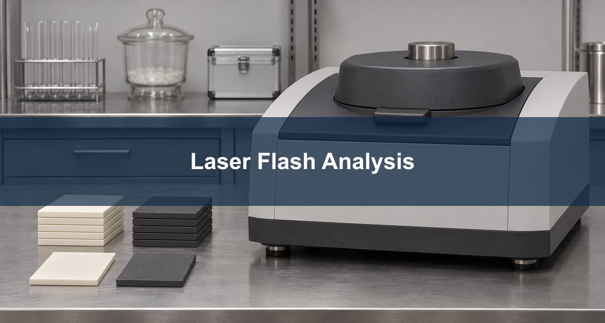
Laser Flash Analysis: What the Instrument Measures
A short light pulse heats one face of a suitable specimen. The instrument tracks the temperature rise on the opposite face and uses the shape of that response and specimen thickness to infer thermal diffusivity. For a conventional plane-parallel sample measured through its thickness, the result describes that direction. Ask the lab to identify the measurement direction rather than assuming it is in-plane.
Ask for the specimen description and fit method. Heat loss, pulse duration and optical behavior may affect the transient, so a report that says only “laser flash” gives too little context for comparing close results.
Thermal Diffusivity vs. Thermal Conductivity
Thermal diffusivity describes how fast a temperature disturbance spreads. Thermal conductivity describes the heat flow a material supports for a given temperature gradient. Materials can store different amounts of heat per unit volume, so they need not rank the same way on the two metrics.
For the module, use conductivity for a first steady-state heat-path estimate. Keep the measured diffusivity and related properties when evaluating the time response. Do not compare a supplier’s number in mm²/s with another supplier’s number in W/(m·K).
Thermal Diffusivity Units: Check Each Input Before Comparing Reports
To calculate conductivity in W/(m·K) with SI inputs, convert mm²/s to m²/s by multiplying by 10−6. Convert g/cm³ to kg/m³ by multiplying by 1,000. If specific heat is given in J/(g·K), multiply by 1,000 to obtain J/(kg·K). Keep the original units visible next to each converted value.
| Input | Example for one ceramic | What to verify |
|---|---|---|
| Diffusivity, α | 12 mm²/s = 0.000012 m²/s | Direction and temperature of the test |
| Density, ρ | 3.8 g/cm³ = 3,800 kg/m³ | Same material construction and appropriate temperature basis |
| Specific heat, cp | 0.780 J/(g·K) = 780 J/(kg·K) | Measured or sourced value for the same material and temperature |
Thermal Diffusivity Formula: Recalculate the Reported Conductivity
Rearrange α = k/(ρcp) to get k = αρcp. In the example, 0.000012 × 3,800 × 780 gives 35.568 W/(m·K), consistent with a rounded result of 36 W/(m·K). This verifies the arithmetic only. It does not validate the test or prove the result is a guaranteed minimum.
If the report cannot be reproduced, ask for the exact inputs, units, temperatures and whether the output describes a homogeneous material or an effective multilayer result. Do not reconcile a mismatch by silently inserting a datasheet value.
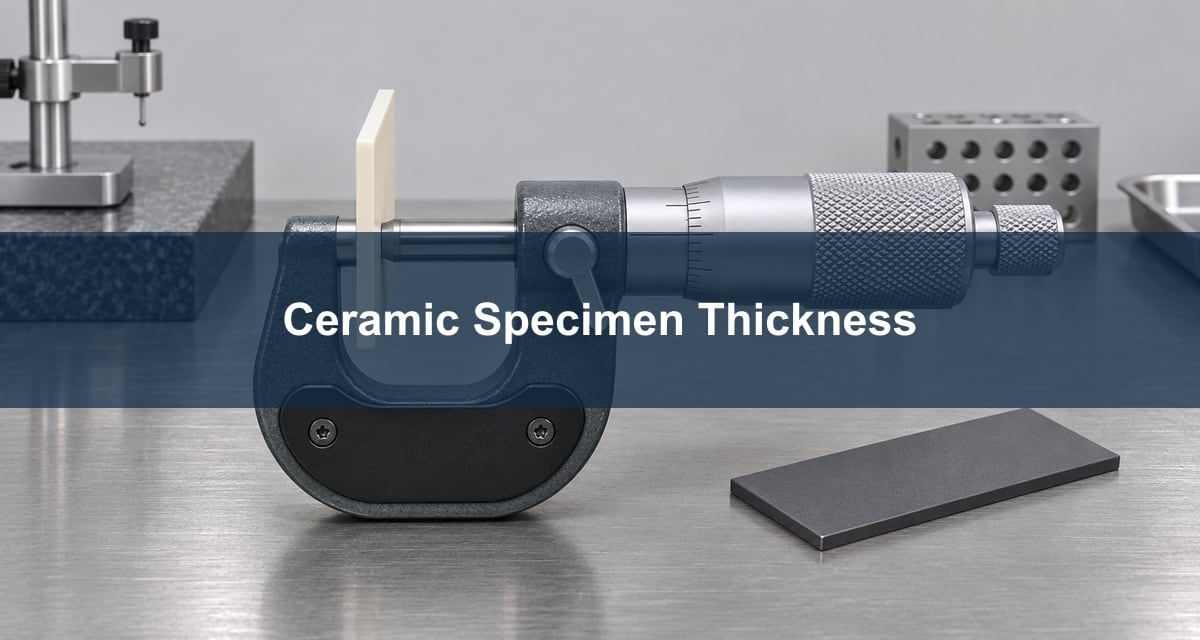
Specific Heat Capacity: Ask Where the Value Came From
Specific heat is the energy needed per unit mass and temperature rise. A lab can use a comparative method to estimate it or use documented material data when appropriate. The source matters: conductivity changes in direct proportion to cp when the other inputs stay fixed. In the example, a 5% higher assumed cp gives a 5% higher calculated conductivity.
Request separate provenance for density and specific heat. A literature value for a nominal composition is not automatically a value for the received grade, porosity or operating temperature. If the comparison margin is small, request a matched retest or a defensible uncertainty estimate.
Thermal Conductivity Measurement Methods: Bare Coupon vs. Finished Stack
Use a bare specimen test to qualify ceramic material. A metallized stack or bonded coupon may require a multilayer model, particularly when an interface affects the response. It should not be reduced to a bulk ceramic value by inserting the total thickness into a single-layer calculation.
| Specimen | Useful decision | Limit |
|---|---|---|
| Unmetallized ceramic | Compare material lots or grades under matched conditions. | Does not include copper or bond interfaces. |
| Metallized coupon | Compare a controlled stack using an appropriate model. | Does not reproduce the mounted module. |
| Production assembly | Verify junction or other defined temperature limits under actual mounting and load. | Does not isolate bulk material conductivity by itself. |
Alumina vs. Aluminum Nitride Thermal Conductivity: Compare the Actual Grades
When comparing alumina and aluminum nitride, match specimen direction, temperature and reporting method. Compare exact grades rather than generic material names. A material with higher conductivity is worth evaluating if the ceramic accounts for a meaningful part of the heat path, but the assembly may still be limited by a bond, interface or cooler.
For the module, review dielectric isolation, metallization compatibility and mechanical requirements alongside thermal data before approving a substitution. Use a material report to screen candidates, not to qualify every feature of a different construction.
Thermal Resistance Calculation: Set a Separate Assembly Check
For ideal one-dimensional conduction, estimate the slab’s resistance as thickness divided by conductivity times area. At 0.63 mm thickness, 100 mm² area and 35.568 W/(m·K), that gives about 0.18 K/W for the ceramic slab. It excludes spreading, metallization, joints and cooling. The estimate is useful for scale, not as a prediction of junction temperature.
Release the material against the agreed lot-level requirement and the assembly against its own thermal target. Record operating power, measurement endpoints, boundary conditions and method. The Best Technology assembly thermal test guide shows why a change at the mounting interface can alter the measured temperature independently of the substrate.
Frequently Asked Questions
Does laser flash analysis directly measure conductivity?
It typically determines diffusivity from the transient. Conductivity can be derived using compatible density and specific heat.
Can I compare values at two different temperatures?
Do not treat them as equivalent without a justified temperature comparison or a matched test.
Is a graphite coating part of the ceramic’s conductivity?
It may be a specimen preparation aid. Ask the lab to document the coating and account for its influence where relevant.
Does a higher conductivity guarantee a cooler component?
No. Check the complete heat path and mounting conditions.
What if the two suppliers use different specimens?
Use the figures for preliminary screening only until the material construction and test conditions can be aligned.
Can the number prove electrical isolation?
No. Use the specified dielectric or insulation test for that requirement.
Why request the thickness used in the fit?
It is an input to deriving diffusivity. Nominal stock thickness may not represent the measured specimen.
Should I accept a report with no raw values?
If it controls a material release, ask for the input values and evidence needed to apply the agreed decision rule.
References
Discuss Your Ceramic PCB Requirements
Send the ceramic grade, copper construction, thermal report and planned acceptance test to sales@bestpcbs.com for a Best Technology review. Mark which values are purchasing requirements and which are design inputs.
You may also like



Tags: ceramic PCB, Laser Flash Analysis, thermal conductivity, Thermal Diffusivity