PCB manufacturing PCB manufacturing
Home > Blog

High Temperature PCB

Ceramic PCB High Temperature Resistant Guide: Materials, CTE and Thermal Conductivity
Friday, July 10th, 2026

A ceramic PCB can be a strong choice for high temperature electronics when FR4, standard metal core PCB, or ordinary laminate materials cannot provide enough temperature stability, insulation, or heat transfer. The right material still depends on actual operating temperature, heat load, thermal cycling, CTE matching, copper structure, assembly method, and inspection requirements.

What Does Ceramic PCB High Temperature Resistant Mean?

Ceramic PCB high temperature resistant means the circuit substrate can keep useful electrical insulation, dimensional stability, and mechanical integrity in a hotter environment than many organic PCB materials can tolerate.
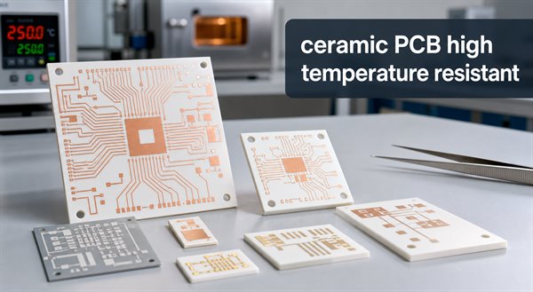
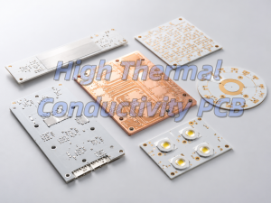
Ceramic PCB high temperature resistant substrates with keyword overlay

For PCB buyers, high temperature resistance should not be read as one simple number. A board may survive a short thermal event but still fail in long-term operation because of copper stress, solder joint fatigue, ceramic cracking, metallization adhesion, component limits, or repeated thermal cycling.

A ceramic PCB is usually chosen when the substrate must support both heat transfer and electrical reliability. Alumina, aluminum nitride, silicon nitride, thick film ceramic circuits, DBC ceramic PCB, and other ceramic substrate options each solve a different high temperature problem.

Why Choose Ceramic PCB for High Temperature Applications?

Choose ceramic PCB for high temperature applications when the board must handle heat, insulation, and dimensional stability at the same time.

Standard FR4 PCB works well for many electronic products, but its resin system limits long-term high temperature reliability. High Tg FR4 can improve heat resistance, yet it is still an organic laminate. Ceramic substrates are inorganic, so they can offer stronger temperature stability and lower thermal expansion in harsh environments.

Common high temperature ceramic PCB applications include LED modules, power electronics, semiconductor modules, automotive electronics, industrial sensors, heating control circuits, aerospace electronics, high-voltage insulation circuits, and compact assemblies where heat cannot be removed easily through a standard board stack.

PCB Option High Temperature Fit Buyer Note
FR4 PCB Good for many standard products Check Tg, Td, operating temperature, and soldering profile
High Tg FR4 Better than standard FR4 Useful when temperature is elevated but not extreme
Metal core PCB Good heat spreading Often used for LEDs and power boards, but dielectric layer matters
Ceramic PCB Strong heat resistance and insulation Best when heat, voltage, reliability, and size all matter
DBC ceramic PCB Power module and high current applications Useful when copper thickness and heat transfer are both important

What Temperature Can a Ceramic PCB Withstand?

A ceramic PCB can often tolerate much higher substrate temperatures than organic PCB laminates, but the real usable temperature depends on material, metallization, assembly, components, solder, coating, and operating time.

It is risky to ask only for “maximum temperature.” For a production design, define the continuous operating temperature, peak temperature, dwell time, temperature cycling range, heating and cooling rate, and whether the board will carry power during the high temperature condition.

EBest Circuit’s ceramic PCB page lists high-temperature resistance as a ceramic PCB process advantage and covers ceramic materials including Al2O3 and AlN. Public technical references also commonly describe ceramic substrates as suitable for high-power and high-reliability applications where FR4 temperature limits are not enough.

How Does Ceramic PCB Thermal Conductivity Affect Heat Dissipation?

Ceramic PCB thermal conductivity affects how quickly heat can move through the substrate from components to a heat sink, chassis, or surrounding structure.
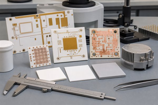
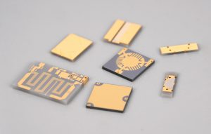
Ceramic PCB material samples for thermal conductivity and CTE review

Thermal conductivity is not the same as temperature resistance. A material can tolerate high temperature but still conduct heat poorly. Alumina ceramic PCB is often cost-effective and stable, while AlN ceramic PCB usually provides much higher thermal conductivity for stronger heat transfer. Silicon nitride may be selected when mechanical strength and thermal cycling reliability are more important.

Material Thermal Behavior Typical Decision Logic
Al2O3 / alumina Moderate ceramic thermal conductivity Cost-effective choice for many high temperature ceramic PCB projects
AlN Higher thermal conductivity Useful for high-power modules and compact heat paths
Si3N4 Good strength and thermal cycling behavior Consider when mechanical reliability is a major concern
Metal core PCB Good heat spreading through metal base Good for many LED and power applications, but not always ceramic-level insulation

For accurate selection, review the full thermal path: component package, solder layer, copper area, ceramic thickness, substrate material, interface material, heat sink, airflow, and mounting pressure.

Why Does Ceramic PCB CTE Matter in High Temperature Design?

Ceramic PCB CTE, or coefficient of thermal expansion, matters because materials expand and contract as temperature changes.

If the ceramic substrate, copper layer, solder joint, component package, and mounting structure expand at very different rates, thermal cycling can create stress. That stress may lead to cracks, delamination, solder fatigue, conductor damage, or loss of electrical reliability.

CTE matching is especially important in power modules, high-temperature sensors, automotive electronics, aerospace electronics, and products exposed to repeated heating and cooling. Buyers should provide the expected temperature cycle, not only the maximum temperature.

Al2O3 vs AlN vs Si3N4: Which Ceramic PCB Material Should You Choose?

The best ceramic PCB material depends on whether the design needs lower cost, higher thermal conductivity, stronger mechanical reliability, or better thermal cycling performance.

Al2O3 is often the first ceramic PCB material to review because it is widely used and cost-effective. AlN is usually selected when the design needs much stronger heat transfer. Si3N4 can be attractive for demanding thermal cycling or mechanical stress conditions, but availability, process route, and cost should be reviewed early.

Material Strength Limitation Best Use
Al2O3 ceramic PCB Stable, economical, mature Lower thermal conductivity than AlN General high temperature ceramic PCB, sensors, LEDs, hybrid circuits
AlN ceramic PCB High thermal conductivity Higher cost and stricter processing High-power modules, compact thermal designs, advanced LEDs
Si3N4 ceramic PCB Mechanical strength and thermal cycling potential Cost and process availability need review Demanding power electronics and reliability-focused applications

Ceramic PCB vs FR4 vs Metal Core PCB for High Temperature Use

Ceramic PCB, FR4, and metal core PCB solve different temperature and heat problems, so the best choice depends on the real operating environment.

FR4 is usually best when cost, multilayer routing, and normal operating temperatures matter most. Metal core PCB is often useful when heat spreading is needed from LEDs or power devices. Ceramic PCB becomes more attractive when the board must combine high temperature stability, insulation, compact size, and reliable heat transfer.

If the circuit has high voltage, high heat flux, repeated thermal cycling, or a small heat path, ceramic PCB should be reviewed before the layout is locked.

Which Ceramic PCB Manufacturing Process Fits High Temperature PCBs?

The manufacturing process should match the temperature, current, line width, copper thickness, and reliability requirement.

Thick film ceramic PCB is useful for hybrid circuits, sensors, and designs that need fired conductor patterns on ceramic. Thin film ceramic PCB supports finer circuit features and precision applications. DBC ceramic PCB is often used where bonded copper, power handling, and heat transfer are important.

Process Useful For High Temperature Note
Thick film Sensors, hybrid circuits, fired conductors Review conductor paste and firing system
Thin film Fine lines, precision circuits, compact modules Useful when pattern accuracy matters
DBC Power modules and higher current paths Review copper thickness, ceramic thickness, and thermal cycling
HTCC / LTCC Multilayer ceramic structures and packages Use when the design needs ceramic multilayer integration

What Design Checks Help Prevent High Temperature PCB Failure?

High temperature PCB failure is often caused by the whole assembly, not only the ceramic substrate.

  • Check continuous temperature, peak temperature, and thermal cycling range.
  • Review CTE compatibility between ceramic, copper, solder, and component packages.
  • Confirm copper thickness and conductor adhesion for the process.
  • Check solder alloy, attachment method, and component temperature ratings.
  • Review ceramic thickness, board outline, holes, slots, and edge stress.
  • Confirm whether conformal coating, potting, or enclosure materials can survive the same temperature.
  • Define inspection and reliability testing before production.

For procurement teams, a “high temperature ceramic PCB” quote should include more than Gerber files. It should include application temperature, power dissipation, operating environment, assembly requirements, and reliability expectations.

What Should You Provide for a High Temperature Ceramic PCB Quote?

A complete RFQ helps the manufacturer choose the right ceramic material, process, tolerance, copper structure, and test plan.
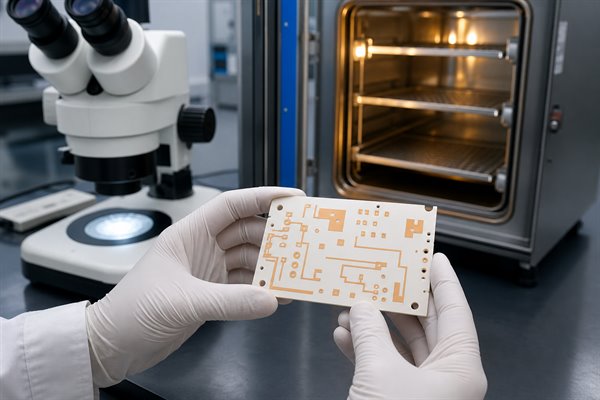
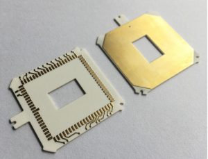
High temperature ceramic PCB inspection after thermal testing
  • Gerber files, drill file, and mechanical drawing.
  • Preferred ceramic material, such as Al2O3, AlN, or Si3N4.
  • Operating temperature, peak temperature, and temperature cycle profile.
  • Power dissipation, current load, and heat source area.
  • Copper thickness, conductor method, and surface finish.
  • Minimum line width, spacing, hole size, and tolerance requirements.
  • Assembly method, component type, solder requirement, and testing needs.
  • Prototype quantity, mass production estimate, and delivery expectation.

How EBest Circuit Supports High Temperature Ceramic PCB Projects?

EBest Circuit supports ceramic PCB manufacturing and related PCB/PCBA services for customers evaluating high temperature, high thermal conductivity, and high reliability circuit requirements.

Relevant capabilities include ceramic PCB, thick film ceramic PCB, thin film ceramic PCB, DBC ceramic PCB, FR4 PCB, metal core PCB, component sourcing, and PCB assembly. For high temperature ceramic PCB projects, the engineering review should focus on material, thermal conductivity, CTE, copper structure, process route, testing, and assembly compatibility.

If the design is still early, send the working temperature, heat source details, voltage/current requirement, and expected environment. This helps the team suggest whether Al2O3, AlN, Si3N4, DBC, thick film, thin film, FR4, or metal core PCB is the better starting point.

FAQ

Is ceramic PCB good for high temperature?

Yes. Ceramic PCB is often good for high temperature electronics because ceramic substrates provide strong insulation, stable dimensions, and better heat resistance than many organic PCB laminates. The final reliability still depends on copper, solder, components, assembly, and thermal cycling.

What is the best material for high temperature ceramic PCB?

There is no single best material for every high temperature ceramic PCB. Al2O3 is often cost-effective, AlN is useful when high thermal conductivity is needed, and Si3N4 may be considered when mechanical strength and thermal cycling reliability are major concerns.

Is thermal conductivity the same as temperature resistance?

No. Thermal conductivity describes how well heat moves through a material. Temperature resistance describes how well the material and assembly survive heat. A board can tolerate high temperature but still need better heat spreading, or conduct heat well but fail because of CTE stress or assembly limits.

Why is CTE important for ceramic PCB?

CTE matters because ceramic, copper, solder, and components expand at different rates when temperature changes. Poor CTE matching can create mechanical stress, which may cause cracking, delamination, or solder joint fatigue during thermal cycling.

Can FR4 be used for high temperature PCB?

FR4 can be used in many moderate-temperature electronics, and high Tg FR4 can improve thermal margin. For harsher environments, stronger insulation, high heat flux, or repeated thermal cycling, ceramic PCB or another high temperature substrate may be a better fit.

When should I choose metal core PCB instead of ceramic PCB?

Choose metal core PCB when heat spreading through a metal base is enough and the circuit does not require ceramic-level insulation, temperature stability, or CTE behavior. LEDs and some power boards often use metal core PCB, while ceramic PCB fits more demanding thermal and reliability cases.

What affects the cost of high temperature ceramic PCB?

Cost depends on ceramic material, substrate thickness, board size, process type, copper thickness, line width, holes, tolerance, surface finish, inspection, assembly, quantity, and lead time. AlN, fine features, tight tolerances, and special reliability testing usually increase cost.

What files are needed for a high temperature ceramic PCB quote?

Send Gerber files, drill files, drawings, stackup notes, ceramic material preference, operating temperature, thermal cycling profile, current and voltage requirements, copper thickness, surface finish, quantity, and assembly or testing requirements if needed.

Conclusion

A ceramic PCB can solve high temperature PCB problems when the design needs more than ordinary laminate heat resistance. The right choice depends on temperature profile, thermal conductivity, CTE, material type, manufacturing process, copper structure, assembly method, and quality inspection.

If you are evaluating high temperature ceramic PCB, Al2O3 PCB, AlN PCB, DBC ceramic PCB, thick film ceramic PCB, or ceramic PCB assembly, EBest Circuit can review your drawings and help choose a practical manufacturing path. Contact our engineering team for technical support and a quote at sales@bestpcbs.com.
You may also like

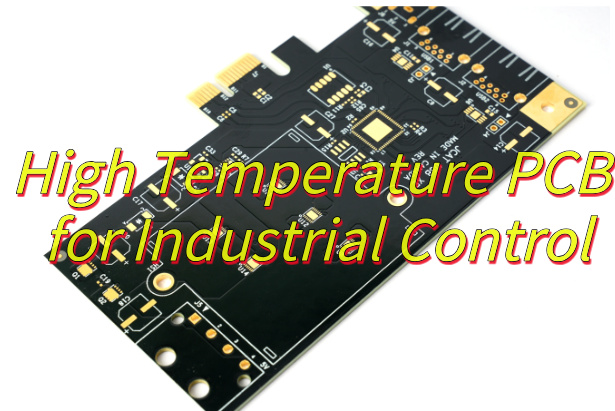
High Temperature PCB for Industrial Control
Wednesday, June 25th, 2025

Looking for high temperature PCB for your project? This article explores high-temperature PCB solutions from material selection to thermal management and cost-performance optimization for harsh environments.

18-Year High Temperature PCB Manufacturing Expert | Rapid Prototyping & Precision Assembly Your Hardware Accelerator!

PCB Manufacturing Service Offered include:

24-Hour Rapid Prototyping: Industry’s Fastest Delivery, 10% Off on Rush Orders
Aerospace Grade Quality Control: 6-Layer HDI Board ±0.05mm Accuracy, 100% AOI Full Inspection
Full-Stack Services: From Design Review to Mass Assembly, Direct Supply from ISO-Certified Factory

Order Now and Get a Free DFM Analysis Report, Making Your IoT/Industrial Control Projects One Step Ahead! Contact us now: sales@bestpcbs.com.

What Is High Temperature PCB?

High temperature PCBs or High Tg PCBs are specialized circuit boards designed to operate reliably in industrial environments with elevated temperatures. These boards utilize thermally stable materials such as polyimide-based substrates and high-temperature laminates that maintain structural integrity and electrical performance at sustained temperatures between 150°C and 250°C.

In industrial control systems, these PCBs feature enhanced copper plating for better heat dissipation and modified dielectric materials that prevent thermal degradation. The manufacturing process incorporates precise thermal management techniques to ensure consistent performance in applications like factory automation, power electronics, and process monitoring equipment.

Their ability to withstand thermal cycling and harsh operating conditions makes them indispensable for industrial applications where standard PCBs would experience premature failure due to heat-related stress or material breakdown. The design considerations include optimized trace layouts and robust interlayer connections to maintain signal integrity under continuous thermal load.

What Is High Temperature PCB?

What Is Material of High Temperature PCB?

Material of high temperature PCB:

  • Polyimide Resins – The most common base material for high temperature PCBs, offering continuous operation up to 260°C with excellent chemical resistance and mechanical stability.
  • Ceramic-Filled PTFE Composites – Provide superior thermal conductivity while maintaining electrical insulation properties, ideal for high-frequency applications in industrial environments.
  • High Tg FR-4 Variants – Fiberglass-reinforced epoxy laminates with glass transition temperatures above 170°C, suitable for cost-sensitive applications with moderate heat requirements.
  • Thermally Conductive Prepregs – Specialized bonding layers that maintain adhesion at elevated temperatures while facilitating heat transfer between board layers.
  • Heavy Copper Foils – Thicker copper layers (2-20 oz) that enhance current carrying capacity and improve heat dissipation across the circuit board.
  • High Temperature Solder Masks – Modified coatings that withstand repeated thermal cycling without cracking or discoloration, protecting underlying circuits.
  • Metal Core Substrates – Aluminum or copper bases that function as integrated heat spreaders, particularly valuable for power electronics in industrial controls.
  • Ceramic Substrates – Used in extreme environments, offering unmatched thermal performance with operating temperatures exceeding 350°C.
  • Specialty Thermoplastics – Materials like PEEK and PEI that combine high temperature resistance with chemical inertness for harsh industrial applications.

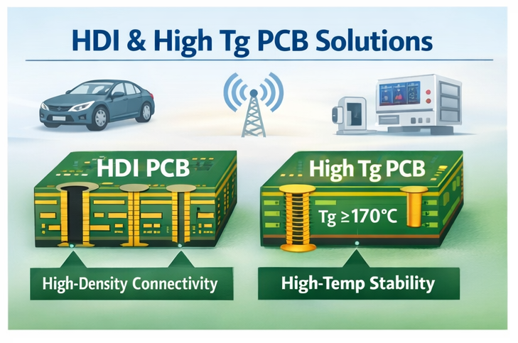
When to Use High Tg PCB?

Below are when to use high Tg PCB:

  • Lead-Free Soldering Processes‌: When manufacturing requires RoHS-compliant lead-free soldering (peak temperatures 250-260°C), standard FR-4 (Tg 130-140°C) risks delamination. High Tg materials (Tg ≄ 170°C) maintain structural integrity during repeated thermal cycles.
  • High-Power Industrial Equipment‌: For motor drives, power converters, or servo controllers with concentrated heat generation, high Tg substrates resist warping and prevent copper trace separation caused by prolonged operation above 120°C.
  • Multi-Layer Board Designs‌: Complex industrial PCBs with 8+ layers demand high Tg prepregs to withstand lamination temperatures while ensuring interlayer bonding strength, reducing via cracking risks during thermal expansion.
  • Harsh Environment Operations‌: In facilities like foundries or chemical plants where ambient temperatures exceed 100°C, high Tg materials (preferably Tg > 180°C) prevent resin softening and preserve dielectric properties.
  • Extended Product Lifespan Requirements‌: Industrial automation systems with 10+ year service expectations benefit from high Tg PCBs’ slower thermal degradation rates, minimizing insulation resistance decline over time.
  • Thermal Cycling Conditions‌: Applications experiencing frequent temperature fluctuations (e.g., outdoor control cabinets, metal processing machinery) require high Tg substrates to resist cumulative CTE mismatch damage.
  • High-Density Component Mounting‌: Boards with fine-pitch BGAs or miniaturized components need high Tg materials’ superior dimensional stability to maintain alignment during assembly and operation.
When to Use High Tg PCB?

How to Optimize High Temperature PCB Design for Efficient Heat Dissipation?

Methods about how to optimize high temperature PCB design for efficient heat dissipation:

Select Thermally Conductive Substrates

  • Use High Temperature PCB Design materials like aluminum-backed or copper-clad laminates to enhance heat transfer away from components. These substrates often feature thermal conductivity ratings exceeding 1.0 W/m·K, significantly reducing hotspot formation in power-intensive industrial controls.

Incorporate Thick Copper Traces

  • Design traces with 2–3 oz/ftÂČ copper thickness to minimize electrical resistance and heat generation in high-current paths. This approach is critical for motor drives or power supplies, where thinner traces would otherwise act as focal points for thermal stress.

Strategically Place Heat-Generating Components

  • Position components like MOSFETs, diodes, or inductors near thermal vias or metallic cores. Aligning these elements with PCB edges or dedicated heat sinks ensures direct heat dissipation into chassis mounts, preventing thermal runaway in enclosed industrial enclosures.

Leverage Thermal Vias and Ground Planes

  • Implement staggered arrays of thermal vias (0.2–0.3 mm diameter) beneath high-power devices to spread heat across inner ground planes. This technique reduces localized temperature spikes by 15–20% in multilayer boards used for factory automation controllers.

Optimize Component Spacing and Airflow

  • Maintain minimum clearances of 3–5 mm between heat-sensitive components and heat sources. Pair this with forced-air cooling channels or natural convection pathways to lower junction temperatures by 25–30% in compact industrial IoT gateways.

Use Thermal Interface Materials (TIMs)

  • Apply phase-change pads or graphite sheets between PCBs and heat sinks to reduce thermal resistance. TIMs with 3–5 W/m·K conductivity improve heat transfer efficiency in power generation control modules operating at 180°C ambient temperatures.

Simulate and Validate Thermal Performance

  • Conduct computational fluid dynamics (CFD) simulations early in the High Temperature PCB Design phase to identify hotspots. Iterate on copper weights, via placements, and component orientations based on simulation data to ensure compliance with industrial thermal standards.

Why Choose High Temperature PCB for Industrial Control?

Reasons why choose high temperature PCB for industrial control:

Uninterrupted Operation in Extreme Heat

  • High temperature PCBs ensure industrial control systems function reliably in environments exceeding 150°C, such as near furnaces, engines, or solar inverters. By resisting thermal degradation, they minimize unexpected downtime, directly reducing production losses and maintenance costs.

Extended Service Life

  • Materials like polyimide and ceramic-reinforced laminates resist cracking, delamination, and solder joint fatigue under repeated thermal cycling. This durability translates to fewer replacements and lower lifecycle costs for equipment in power plants or automated manufacturing lines.

Stable Signal Integrity

  • Dielectric formulations in High temperature PCBs maintain consistent electrical properties despite prolonged heat exposure. This prevents timing errors or data corruption in precision control systems, safeguarding product quality and operational safety.

Resistance to Harsh Chemicals

  • Industrial environments often involve oils, solvents, or corrosive gases. High temperature PCBs with chemically inert coatings and sealed edges resist corrosion, reducing the need for protective enclosures and frequent inspections.

Compliance with Safety Standards

  • Using high temperature PCBs helps meet stringent industry certifications (e.g., UL 94V-0 for flame resistance) without additional modifications. This streamlines regulatory approvals for medical devices, aerospace components, or heavy machinery.

Cost-Effective Performance at Scale

  • While high temperature PCBs may have a higher upfront cost, their ability to withstand thermal stress reduces long-term expenses related to repairs, replacements, and production delays. For high-volume industrial applications, this ROI becomes evident within 2–3 years.
Why Choose High Temperature PCB for Industrial Control?

How to Maintain Signal Integrity in High Temperature PCB Board for PLC Control System?

Methods about maintaining signal integrity in high temperature PCB board for PLC control system:

  • Select Low-Loss Dielectric Materials‌: Choose substrates with stable dielectric constants (Dk) and low dissipation factors (Df) across operating temperatures to minimize signal attenuation at high frequencies.
  • Control Impedance with Thermal Compensation‌: Adjust trace width and spacing based on material expansion rates at elevated temperatures to maintain consistent impedance (e.g., 50Ω/100Ω differential) throughout thermal cycles.
  • Shield Sensitive Signals‌: Route high-speed traces (e.g., clock lines, RS-485) between ground planes or use guard traces to reduce crosstalk and EMI, which worsen with temperature-induced noise.
  • Minimize Via Stubs‌: Use blind/buried vias or back-drilling to eliminate stub effects that cause signal reflections, especially critical in multi-layer designs for PLCs.
  • Optimize Power Delivery Networks (PDNs)‌: Decouple power rails with high-temperature-rated capacitors (X7R/C0G) placed close to ICs, ensuring stable voltage despite parasitic inductance changes from heat.
  • Implement Differential Signaling‌: Prefer differential pairs (e.g., CAN, Ethernet) over single-ended traces to reject common-mode noise amplified by thermal interference.
  • Simulate Signal Behavior Under Heat Stress‌: Perform transient thermal analysis combined with SI tools to predict skew, jitter, and eye diagram degradation at peak temperatures.
  • Validate with High-Temperature Testing‌: Characterize signal rise times, BER, and crosstalk while operating the PCB at maximum rated temperature to verify real-world performance.
How to Maintain Signal Integrity in High Temperature PCB Board for PLC Control System?

How to Ensure the Reliability of Industrial Control PCB under High Temperature Conditions?

Methods about how to ensure the reliability of industrial control PCB under high temperature conditions:

Select Thermally Stable Substrate Materials

  • Choose High Temperature PCB substrates with glass transition temperatures (Tg) exceeding 170°C, such as polyimide or ceramic-filled epoxy. These materials resist softening and dimensional changes at sustained temperatures up to 200°C, ensuring mechanical stability in PLC interfaces or motor drives.

Optimize Copper Trace Geometry

  • Design traces with 2–3 oz/ftÂČ copper thickness to reduce current density and minimize Joule heating. For example, a 10-mil trace carrying 3A current in a power distribution network will operate 15°C cooler than a 1-oz trace, extending solder joint lifespan in industrial actuators.

Implement Component Derating

  • Select capacitors, resistors, and ICs rated for 20–30% above maximum operating temperatures. For instance, using X7R dielectric capacitors (rated for 125°C) in 150°C environments prevents capacitance drift by 10% compared to standard components, stabilizing filter circuits in sensor interfaces.

Enhance Solder Joint Robustness

  • Use SnAgCu (SAC305) solder alloy with 260°C reflow tolerance and apply 5–10% larger solder paste stencils for heat-generating components. This reduces voiding by 40% in BGA packages, preventing solder joint fractures under thermal cycling in VFD controllers.

Incorporate Thermal Vias and Heat Spreaders

  • Place 0.3 mm diameter thermal vias in 1.5 mm arrays beneath power MOSFETs and voltage regulators to conduct heat to inner ground planes. Pair this with 20-mil copper heat spreaders to lower junction temperatures by 25°C in compact PLC modules.

Conduct Accelerated Life Testing

  • Subject prototypes to 1,000 thermal cycles (-40°C to 180°C) and 10,000 hours of continuous operation at 150°C. Identify weak points like delamination or parameter drift in analog-to-digital converters (ADCs) early, reducing field failure risks by 60%.

Apply Conformal Coatings for Environmental Protection

  • Use silicone or parylene coatings with 200°C continuous service ratings to shield against moisture, dust, and chemical contaminants. For example, a 25-ÎŒm parylene layer prevents arc-over in high-voltage relay interfaces exposed to industrial solvents.

Validate via Computational Fluid Dynamics (CFD)

  • Simulate airflow patterns and temperature gradients in enclosed control cabinets to optimize PCB placement. Adjust spacing between boards and add ventilation slots to lower ambient temperatures by 10–15°C in crowded automation panels.

How to Balance Performance and Cost in High Temperature Industrial Control PCB Fabrication?

Below are ways about how to balance performance and cost in high temperature industrial control PCB fabrication:

Select Cost-Effective High-Temperature Substrates

  • Use FR-4 variants with Tg ≄ 170°C (e.g., ISOLA IS410) for moderate thermal demands or polyimide blends (e.g., Dupont Pyralux AP) for temperatures up to 260°C. These materials offer 25–30% lower CTE than standard FR-4, ensuring solder joint reliability at 15–20% lower cost than exotic ceramics.

Design Hybrid Layer Stackups

  • Combine high-performance outer layers (e.g., Megtron 6 for signal integrity) with standard FR-4 cores for inner power planes. This reduces material costs by 15–20% while maintaining thermal stability. For example, a 4-layer board using Megtron 6 for outer layers and FR-4 for inner layers achieves 42% lower transmission loss in power distribution networks.

Optimize Trace Geometry for Current Capacity

  • Use 2–3 oz/ftÂČ copper thickness for high-current paths to minimize Joule heating. For instance, a 15-mil trace carrying 5A reduces temperature rise by 18°C compared to 1-oz copper. Employ thermal simulation tools (e.g., Siemens Simcenter) to identify bottlenecks and adjust trace widths dynamically, avoiding over-engineering.

Implement Smart Component Placement

  • Position heat-generating components (e.g., MOSFETs, inductors) near thermal vias or board edges to leverage natural convection. Maintain 8–10 mm spacing between hot components and temperature-sensitive ICs to prevent thermal runaway. In PLC control modules, this reduces junction temperatures by 12–15°C.

Apply Targeted Thermal Management

  • Use 0.3 mm thermal vias in 1.2 mm arrays beneath power devices, lowering thermal resistance by 22%. Apply 20-mil copper heat spreaders only in critical areas (e.g., under BGA packages) rather than entire boards, cutting material costs by 30%. For example, a 50×50 mm copper spreader reduces hotspot temperature by 28°C in motor drive circuits.

Automate Manufacturing Processes

  • Invest in dual-track reflow ovens with AI-driven temperature profiling. These systems reduce energy consumption by 45% and improve first-pass yield by 5–8% through adaptive heat control. Pair with laser direct imaging (LDI) for ±3ÎŒm linewidth accuracy, eliminating photo tooling costs and reducing setup time by 60%.

Validate via Accelerated Stress Testing

  • Conduct 500-cycle thermal shock tests (-40°C to 180°C) on prototypes to identify weak points early. Replace failed components with equivalents rated for 20% higher temperatures, adding minimal cost while extending MTBF by 2–3x. For example, using X7R capacitors instead of Y5V in 150°C environments prevents 35% capacitance drift.

Conclusion

High-temperature PCBs provide thermal stability, reliability, and signal integrity. Material selection, thermal management, and cost-performance balance are main factors in design. These PCBs are used in PLC systems, automotive electronics, and heavy machinery to prevent delamination, warping, and signal loss under extreme heat.

For high-temperature PCB solutions, contact ‌EBest Circuit (Best Technology)‌. We offer ‌24/7 rapid prototyping‌, ‌military-grade quality control‌, and ‌free DFM analysis‌ to ensure robust performance. ‌Request a quote today‌ to advance your industrial projects: sales@bestpcbs.com.

You may also like