PCB manufacturing PCB manufacturing
Home > Blog

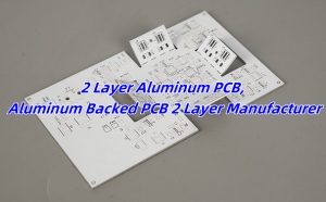
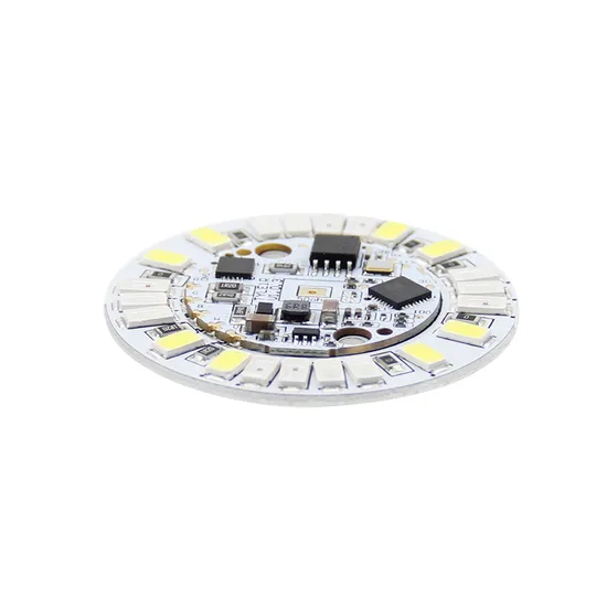
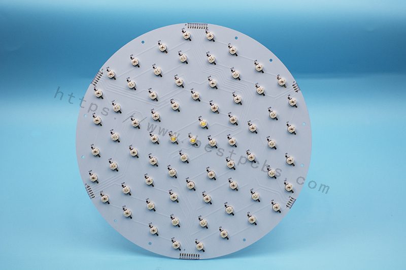
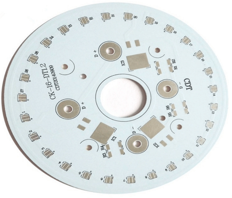
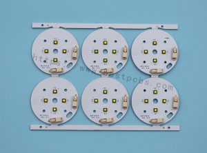
LED Ring PCB Design,Prototype&LED Ring PCB Manufacturer

March 13th, 2025

LED Ring PCB is very important to many modern lighting applications. Because these specialized printed circuit boards allow LEDs to be arranged in a circular configuration, offering uniform lighting with efficient power use. In this blog, we’ll explore together everything you need to know about LED ring PCBs, from their design and materials to the advantages they offer and the best manufacturers to work with.

What Is LED Ring PCB?

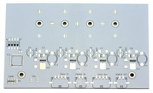
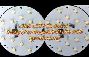
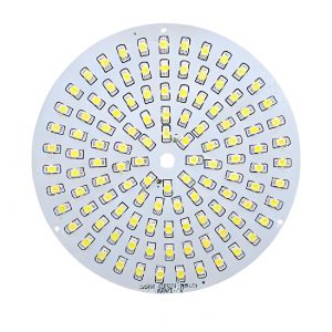
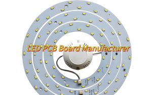
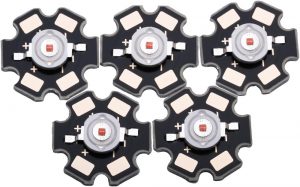
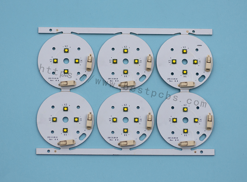
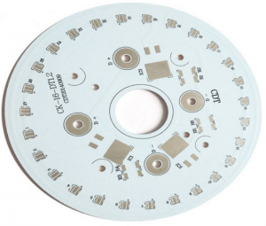
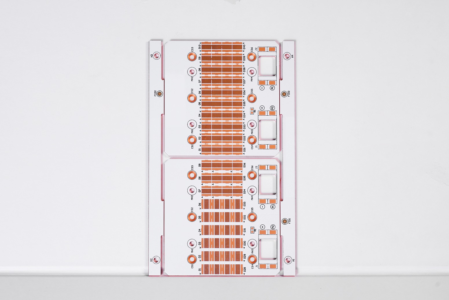
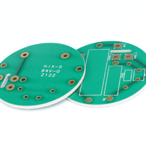
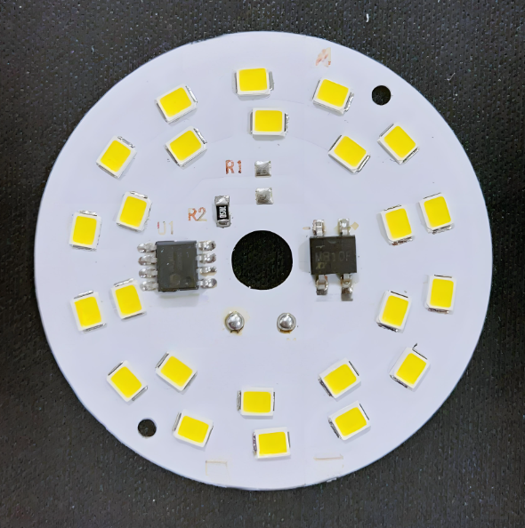
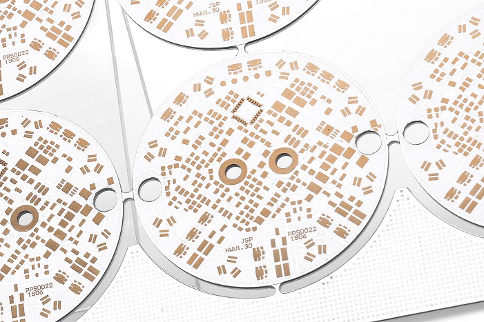
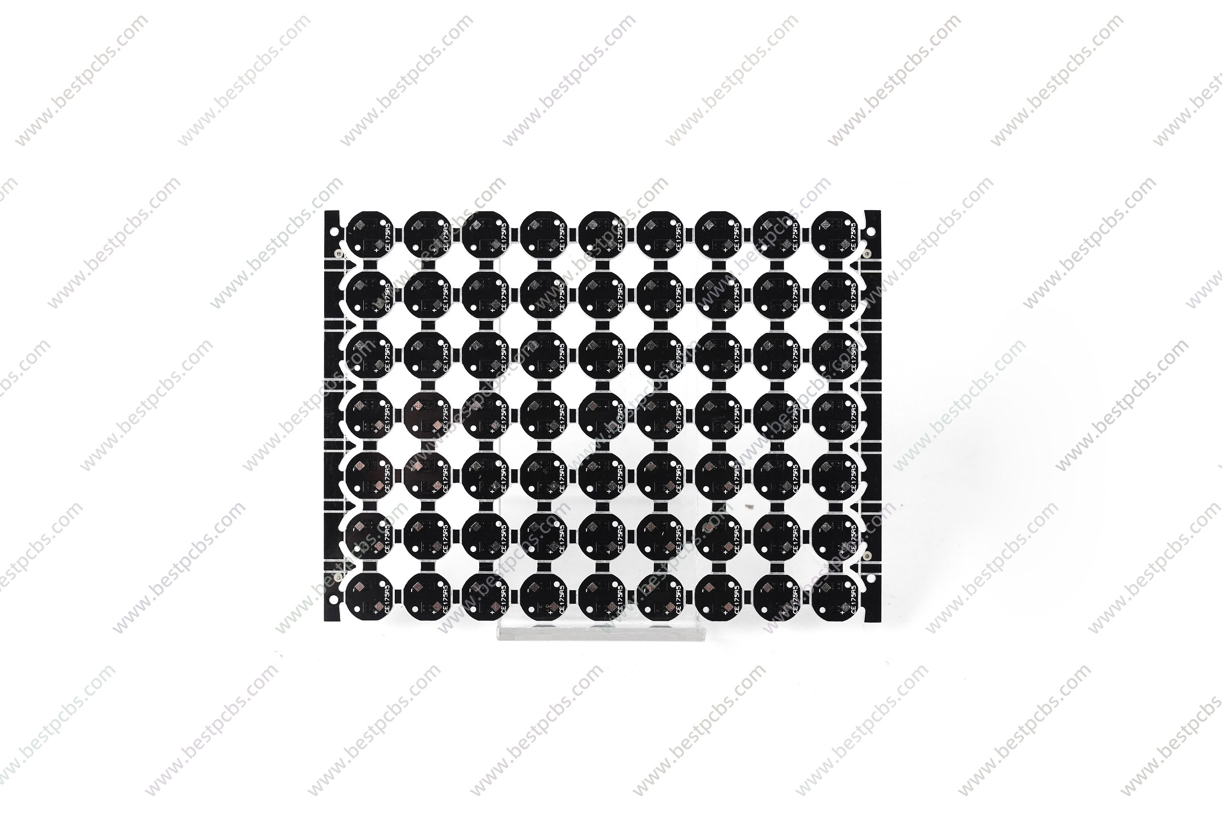
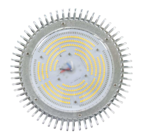
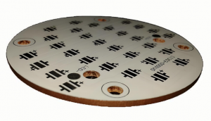
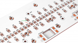
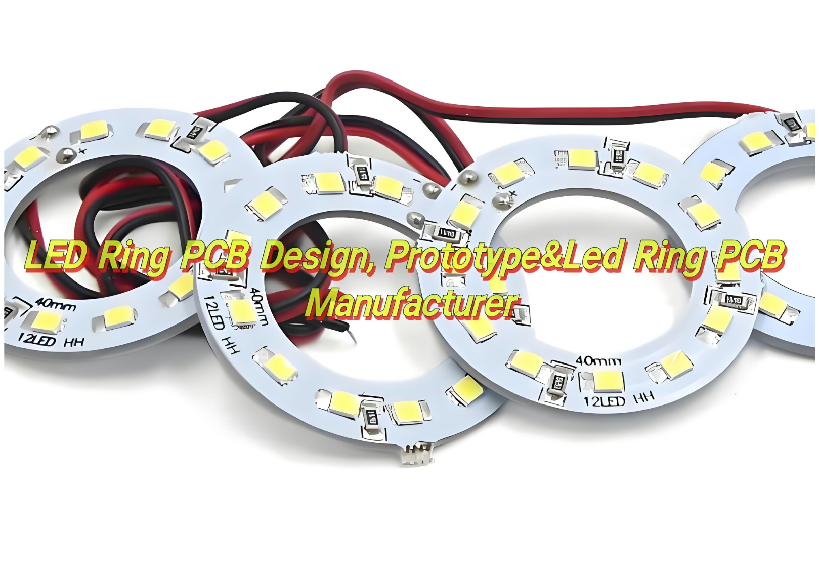
A LED ring PCB is a circular printed circuit board that houses multiple LEDs. These boards are engineered to efficiently manage the distribution of electrical current to each LED, ensuring consistent lighting. The design of the PCB allows LEDs to be placed in a circular pattern, optimizing light output and creating a uniform glow. Whether you’re designing a lighting solution for commercial use, automotive applications, or decorative purposes, LED ring PCBs boards are versatile and customizable, making them a popular choice for a wide range of industries.
Best technology specialize in high quality LED ring PCB design, prototype and manufacturing and PCBA services over 18 years. In order to strictly control every step of production from raw material procurement to finished product delivery, we have established a strict quality system and worked hard to obtain ISO certification. And we adopted automatic optical inspection (AOI) and X-ray, it ensures that each printed circuit board (PCB) meets or even exceeds industry standards. Then we have our own LED PCB manufacturing industry chain and experienced production teams, So we are able to provide you with high quality LED PCB products and fast delivery. Welcome to contact us at sales@bestpcbs.com if you’re interested in us.

Advantages of LED Ring PCB

Here are some of the most significant advantages of LED Ring PCB Board:

  • Uniform Light Distribution: It ensures that the emitted light is even, without bright spots or shadows. It’s ideal for applications like decorative lighting or photography where consistent lighting is crucial.
  • Energy Efficiency: LEDs are known for their energy-saving capabilities, and when placed on a ring PCB, they offer even greater energy efficiency. LED ring PCBs provide high brightness while consuming less power, making them cost-effective in the long run.
  • Compact and Flexible Design: LED ring PCBs come in compact sizes that allow them to fit into tight spaces, such as around cameras, mirrors, or small appliances. Flexible variants allow you to bend and shape the board to suit your needs, which is ideal for automotive or wearable devices.
  • Durability and Longevity: LED ring PCBs are made from high-quality materials that are resistant to wear and tear. Many manufacturers use aluminum or copper substrates, which offer better heat dissipation and contribute to the longevity of the LEDs.
  • Versatility in Applications: From decorative lighting to automotive headlights, LED ring PCBs can be used in many different settings. Their adaptability and efficiency make them an excellent choice for a variety of lighting applications.
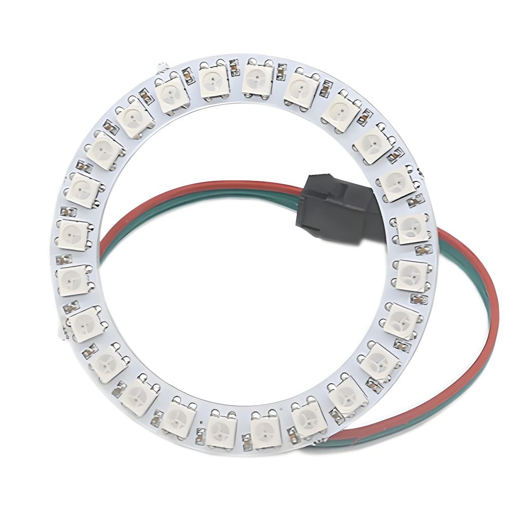
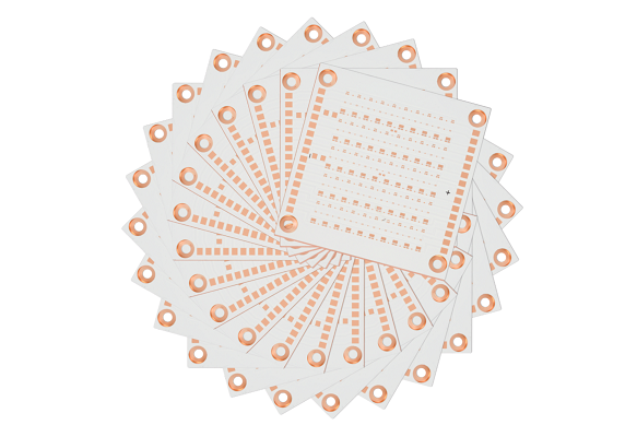
LED Ring Light PCB

Advantages of LED Ring PCB

Application of LED Ring PCB

LED ring PCBs have a wide range of applications. Here are some of the most popular uses:

  • Decorative and Ambient Lighting: Used in interior lighting. Their ability to emit a soft, even light makes them ideal for home decor, accent lighting, and signage. You’ll find them in everything from lighted mirrors to wall sconces.
  • Automotive Lighting: Used in headlamps, taillights, and interior lighting. The circular shape allows for efficient distribution of light, enhancing visibility while also providing a modern aesthetic.
  • Photography and Videography: Use LED ring PCBs to create soft, flattering light for their subjects. These ring lights provide even lighting, minimizing shadows and giving photos a polished look. They’re also popular in video production for creating clean, bright lighting around the camera.
  • Wearables and Devices: Used in wearable technology. For example, they may be incorporated into smartwatches or fitness trackers, where the compact design can be integrated without sacrificing performance.
  • Signage and Advertising: LED ring PCB are used in outdoor signage and advertising displays. Their ability to produce bright, consistent light ensures that these signs are visible even in low-light environments.
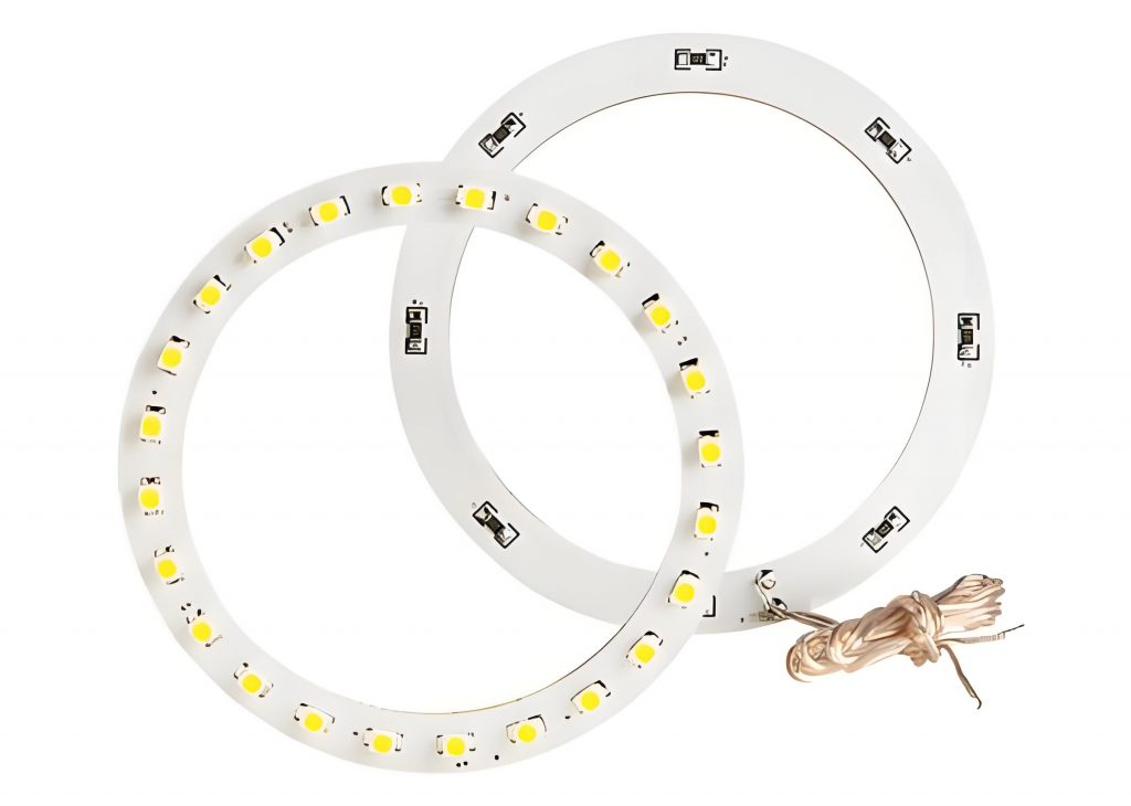
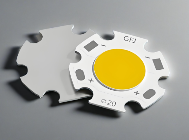
LED Ring PCB Board

Application of LED Ring PCB

Types of LED Ring Light PCB

The classification of LED Ring Light PCB can be detailed from three aspects: materials, number of layers, and structure.

Material Classification

‌Organic Materials‌:

  • ‌Phenolic resin‌: it has the characteristics of weak acid and weak alkali resistance, but not strong acid and strong alkali resistance, insoluble in water but soluble in organic solvents such as acetone and alcohol‌.
  • ‌Glass fiber‌: an inorganic non-metallic material with good insulation, heat resistance, corrosion resistance and high mechanical strength, but brittle and poor wear resistance‌.
  • ‌Polyimide (PI)‌: a high-performance polymer with a variety of forms and molding methods, widely used in aerospace and biomedical fields.
  • ‌Epoxy resin and BT‌: also organic materials with specific application scenarios‌.

‌Inorganic Materials‌:

  • ‌Aluminum substrate‌: a metal-based copper-clad laminate with good heat dissipation function, commonly used in LED lighting products, usually composed of a circuit layer (copper foil), an insulating layer and a metal base layer‌.
  • ‌Copper substrate‌: better thermal conductivity than aluminum substrate and iron substrate , suitable for high-frequency circuits and environments with large changes in high and low temperatures.
  • ‌Ceramic substrate‌: Using its heat dissipation function, it is suitable for specific application scenarios.

Number of Layers Classification

  • ‌Single-sided board‌: Parts are concentrated on one side, and wires are on the other side, suitable for simple circuit requirements.
  • ‌Double-sided board‌: A printed circuit board with conductive patterns printed on both sides, and the conductive patterns on both sides are connected by metallized holes, suitable for more complex circuit requirements.
  • ‌Multilayer board‌: It has three or more layers of conductive patterns, the inner layer is made of conductive patterns and insulating semi-cured sheets laminated and pressed, and the outer layer is copper foil, suitable for circuit design with high density and high performance requirements.

Structural Classification 

  • Rigid board‌: It has excellent bending resistance and support, suitable for circuit design that requires stable support.
  • ‌Flexible board‌: It can be bent and folded, suitable for application scenarios with limited space.

LED PCB Manufacturers

Choosing the right LED ring PCB manufacturer is crucial to ensuring that you receive high-quality products that meet your design specifications. EBest Circuit (Best Technology), with over 18 years of experience in the industry, is a leading manufacturer of LED ring PCBs. Here’s why you should consider partnering with us:

  • Customization Options: We offer a range of customizable LED ring PCB designs. Whether you need specific sizes, shapes, or materials, our team can work with you to create the perfect solution.
  • High-Quality Materials: At EBest Circuit (Best Technology), we use top-tier materials like aluminum, copper, and polyimide to ensure the durability and performance of our LED ring PCBs. Our products are designed to withstand wear and provide long-lasting performance.
  • Competitive Pricing: We offer competitive prices without compromising on quality. Our goal is to provide cost-effective solutions that help bring your designs to life.
  • Global Reach: With a broad customer base and international shipping, EBest Circuit (Best Technology) is equipped to handle projects of any size, whether you’re based locally or internationally.

What Materials Are Used in LED PCB?

The materials used in LED ring PCBs play a significant role in their performance and durability. Here are some of the most common materials:

  • FR4: This is the most commonly used material for LED ring PCBs. It’s a durable and cost-effective substrate that works well for general applications.
  • Aluminum: For high-power applications, aluminum is used as a substrate material. It has excellent heat dissipation properties, making it ideal for high-performance LED ring PCBs.
  • Copper: Copper is often used for high-conductivity applications. It helps to enhance the performance of LED ring PCBs by improving heat transfer and reducing electrical resistance.
  • Polyimide(PI): For flexible designs, polyimide is a popular choice. It’s durable, flexible, and resistant to high temperatures, making it suitable for bending and shaping applications.

How To Design LED Ring PCB?

The process of LED ring PCB design involves several steps:

1. Define Your Requirements and Specifications

The first step in any PCB design is to define your needs and specifications. For LED ring PCBs, this includes determining several key factors:

  • Size and Shape: The size of the LED ring PCB will be dictated by the physical space available in your project. Are you creating a large display, a compact wearable device, or a decorative lighting solution? This will determine the diameter of your PCB and the number of LEDs to be used.
  • LED Configuration: Decide on how many LEDs you want to arrange in the circle. The number of LEDs will influence the brightness and uniformity of the light emitted by the ring. Be sure to space the LEDs evenly for consistent light distribution.
  • Power Requirements: LEDs require a specific amount of voltage and current. Determine the power requirements of the LEDs you plan to use. Ensure the PCB is capable of supplying the necessary power to each LED without overheating or causing circuit instability.
  • Type of LED: LED ring PCBs can house different types of LEDs, such as standard SMD (Surface-Mount Device) LEDs, high-power LEDs, or flexible LEDs. Your choice of LED type will affect the overall design of the PCB.
  • Voltage and Current Considerations: Ensure the voltage and current ratings match the specifications for both your LED ring and the power supply. Consider using a constant current driver to regulate the current supplied to the LEDs, preventing power fluctuations.

2. Select the Right Materials for Your PCB

The materials you choose for your LED ring PCB will significantly affect the performance of the final product. Here are the most commonly used materials:

  • FR4 (Glass-Fiber Epoxy): This is the most common material used in PCB manufacturing. It’s affordable, durable, and suitable for general lighting applications. FR4 is ideal for low to medium power LEDs.
  • Aluminum (Metal Core PCB): For high-power LEDs, aluminum is often used as the base material for the PCB. Aluminum offers superior heat dissipation, preventing the LEDs from overheating and ensuring they operate at peak efficiency. Aluminum-based LED PCBs are commonly used in industrial or automotive applications.
  • Copper: Copper is another material used in LED ring PCBs for its excellent thermal conductivity. Copper-based designs help to quickly dissipate heat generated by high-power LEDs, keeping the system stable and extending its lifespan.
  • Polyimide: For flexible LED ring PCBs, polyimide is a preferred material. It is flexible, durable, and resistant to high temperatures, which makes it ideal for applications that require bending or shaping, such as wearable devices or automotive lighting.

3. Create the Circuit Design and Layout

Once you’ve defined your specifications and chosen the materials, it’s time to create the circuit layout. This is where the technical aspects of your LED ring PCB come into play:

LED Placement: The most important aspect of your design is the placement of the LEDs in a circular configuration. Ensure that the LEDs are evenly spaced to ensure uniform light output. If you’re using high-density LEDs, make sure to account for the necessary spacing to prevent heat buildup.

  • Power Distribution: Plan the power distribution for your LED ring. You must ensure that each LED gets the correct amount of power. For larger designs, consider creating multiple power supply points around the ring to avoid voltage drops and ensure each LED is supplied with stable power.
  • Current Control: In most LED applications, a constant current driver is used to regulate the current flowing through the LEDs. This helps maintain consistent brightness and prevents damage to the LEDs. Design the circuit to include appropriate resistors or constant current drivers to manage power flow effectively.
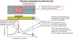
  • Heat Dissipation: LEDs generate heat, so effective heat management is a crucial part of the design. Ensure that your PCB layout includes a clear path for heat dissipation. If you’re using metal-core PCBs, the aluminum or copper material will help carry away heat, but proper trace widths and vias are essential to enhance the thermal conductivity.
  • Trace Widths and Via Sizes: Calculating the correct trace width and via size is critical for ensuring that the PCB can handle the required current without overheating. Use PCB design software that can help you calculate trace widths based on the current requirements for your LEDs.

4. Consider Power Supply and Drivers

The power supply is a key consideration in LED PCB design. LED rings require a regulated power supply to provide a consistent voltage and current to the LEDs. Here’s what you need to think about:

  • Power Supply Type: Depending on the voltage and current requirements of your LED ring, you’ll need to select an appropriate power supply. A common solution is using a constant current driver, which adjusts the current flowing to the LEDs to ensure that they don’t receive too much power, which could lead to burnout.
  • Voltage Regulation: Ensure that the power supply can deliver a constant voltage that matches the voltage requirement of your LEDs. Many LEDs operate on low voltage, and using a higher voltage power supply without regulation could cause instability.
  • Efficiency Considerations: LED drivers and power supplies should be as efficient as possible to minimize energy loss. Look for energy-efficient drivers that can help you reduce power consumption, which is especially important in battery-powered or low-power applications.

5. Prototype and Test Your LED Ring PCB

Once your design is complete, the next step is to prototype your LED ring PCB. This stage involves manufacturing a small batch or a single unit of your design for testing. LED Ring PCB Prototyping is essential for checking the functionality of the circuit, ensuring the LED ring lights up correctly, and verifying that the power distribution is stable.

Here’s how to proceed:

  • Manufacturing the Prototype: After designing the PCB, the next step is to send the design files to a PCB manufacturer for production. The manufacturer will produce the prototype based on the materials, size, and specifications you’ve provided.
  • Testing the Prototype: Once you receive your prototype, it’s time to test it. Check that all LEDs light up as expected, and that there are no issues with flickering or uneven light. Verify that the power distribution works well and that the PCB doesn’t overheat.
  • Thermal Testing: For high-power designs, thermal testing is crucial. Monitor the temperature of the LEDs during operation to ensure that the heat dissipation is working correctly. If the PCB gets too hot, you may need to make adjustments to the trace widths, vias, or use a more efficient heat sink material.
  • Adjustments and Iterations: Based on the results of your testing, you may need to make design adjustments. This might involve tweaking the power distribution, changing materials, or adjusting the size of certain components.

6. Move to Mass Production

Once the prototype has been successfully tested and approved, you can move on to mass production. Working with a reliable LED PCB manufacturer is key at this stage to ensure that the final product meets all of your quality and design specifications.

If you’re looking for a trusted LED PCB manufacturer, EBest Circuit (Best Technology) offers exceptional LED PCB solutions, with extensive experience in designing, prototyping, and mass producing LED ring PCBs.

Conclusion

To sum up, LED ring PCB are essential components for creating efficient, durable, and high-quality lighting systems. Whether you’re designing for decorative lighting, automotive applications, or commercial displays, understanding the key aspects of LED ring PCBs is critical. EBest Circuit (Best Technology)’s expertise in manufacturing LED PCBs ensures that you get top-notch products tailored to your needs. With the right design, materials, and manufacturer, you can create lighting solutions that are both visually appealing and performance-driven.

You may also like

OEM Aluminum Backed PCB Manufacturer

March 12th, 2025

If you’re designing high-performance electronics, you’ve probably heard about aluminum-backed PCBs. These boards are not just a trend—they’re solving real-world problems in industries like LED lighting, automotive, and power supplies. Let’s break down what makes them unique and why they might be the perfect fit for your next project.

What Is an Aluminum Backed PCB?

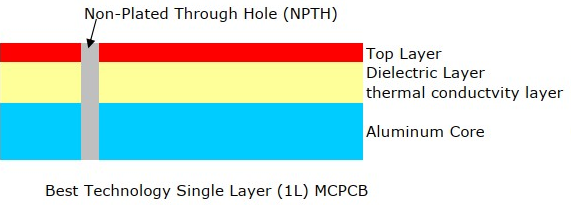
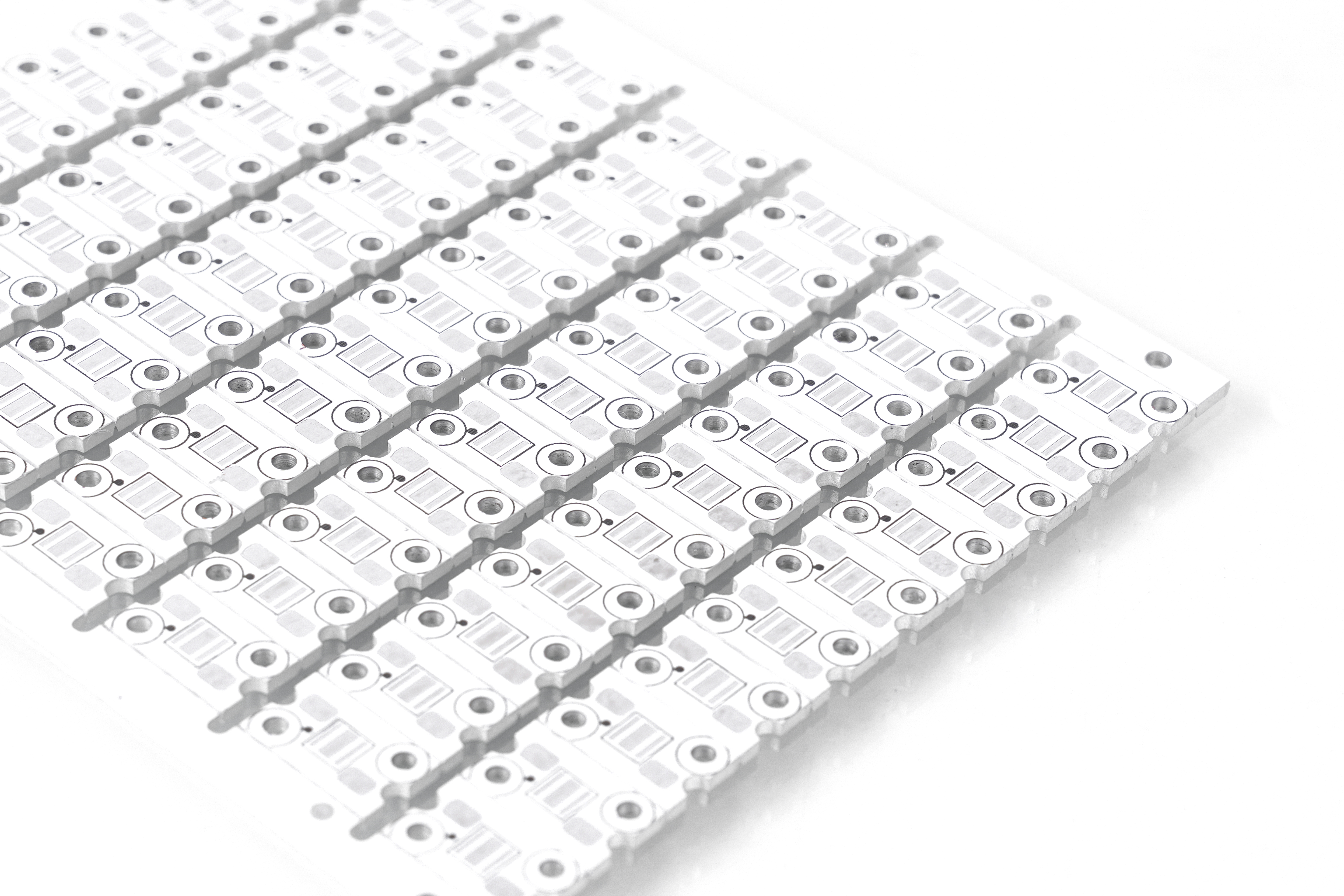
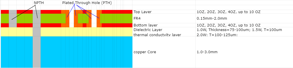
An aluminum-backed PCB (printed circuit board) is a type of metal-core PCB (MCPCB) that uses an aluminum substrate instead of a traditional FR4 base. This layer acts as a heat sink, pulling heat away from components. The design typically includes a dielectric layer, copper circuit layer, and aluminum substrate. Perfect for high-heat applications!

  • Copper Circuit Layer – The top layer, made of copper foil, is used for electrical connections and signal transmission. The copper thickness varies from 1oz to 10oz, depending on current requirements.
  • Dielectric Layer – A thermally conductive but electrically insulating material separates the copper from the aluminum base. The dielectric layer thickness typically ranges from 75”m to 200”m, balancing insulation and thermal transfer.
  • Aluminum Base – This metal substrate serves as a heat sink, drawing heat away from active components. The most common thickness is 1.6mm, though variations from 0.2mm to 3mm exist for different applications.

Aluminum PCB vs. FR4 PCB: Which Wins?

FR4 (fiberglass) PCBs are commonly used in consumer electronics, but aluminum-backed boards shine where heat matters. When choosing between aluminum PCBs and FR4 PCBs, key differences must be considered. The table below highlights critical factors that differentiate them:

ParameterAluminum PCBFR4 PCB
Thermal Conductivity1.0–8.0 W/m·K (varies by dielectric material)0.3–0.5 W/m·K
Thermal Expansion5–20 ppm/°C (closer to copper)14–18 ppm/°C
Heat DissipationExcellent, reduces hot spots  Poor (requires external cooling)
Mechanical StrengthExcellent due to metal baseModerate
Electrical PerformanceConsistent, stableCan degrade under high temperature
WeightHeavier than FR4Lighter
CostHigher due to metal substrateLower
(Aluminum PCB vs. FR4 PCB)

Note:

  • Aluminum conducts heat 8-10 times better than FR4. No more fried components!
  • Aluminum resists bending and cracking. FR4 can warp under stress.
  • FR4 is cheaper for simple designs. Aluminum saves money long-term by reducing cooling needs.
  • Aluminum PCBs last longer in high-temperature environments.
  • Choose FR4 for low-cost, low-power projects. Go aluminum for heat-heavy applications like LEDs or power converters.

Types of Aluminum Backed PCBs

Aluminum PCB can be divided into several types according to layer counts or used materials. But they commonly classified by layers:

1. Single-Layer Aluminum PCB

    Single layer aluminum backed PCB comprises a single conductive copper layer, a dielectric, and an aluminum substrate.

    1 layer Aluminum-Backed PCB stack up

    It always called single sided aluminum PCB due to it only has one layer copper trace. It is the simplest metal core PCB design, and it cost-effective due to simple manufacturing. Commonly used in daily LED lighting like swimming pool lighting, office lighting, street lighting


    2. Double-Layer Aluminum PCB

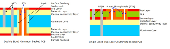
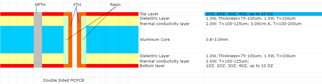
    It has two conductive copper layers, generally separated by the aluminum base. But in another case, both the two copper layers can be located on the top of aluminum base, separated by an insulating layer. It can be called single sided two layers aluminum PCB if made in this way.

    2 layer Aluminum-Backed PCB stack up

    The double layer aluminum PCB provides higher circuit density and improved overall electrical performance. They are commonly used in high power devices where required better heat dissipation like automotive electronics, industrial power modules, and motor control applications.

    3. Multilayer Aluminum PCB

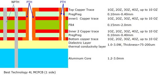
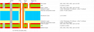
    Different with multi-layer FR4 PCB, the multi-layer aluminum PCB consists of multiple layers of copper and dielectric materials stacked over the aluminum base. Please see its stack-up as following (4 layers aluminum PCB as example):

    multilayer Aluminum-Backed PCB stackup

    It has more complex circuit designs and is used in high-performance applications such as telecommunication systems and aerospace electronics. Multilayer aluminum backed PCB is rarely used and difficult to manufacture because it requires advanced manufacturing techniques for precise layer alignment and thermal control.

    How Thick Is an Aluminum PCB?

    Aluminum PCBs come in various thicknesses depending on the application. The most commonly used thickness values are:

    • Standard (1.0–1.6 mm): Common in LED lighting and consumer electronics. Lightweight and cost-effective.
    • High-Power (2.0–3.0 mm): Used in industrial machinery or EV battery systems. Handles extreme heat and mechanical stress.
    • Custom Thickness: Some manufacturers offer tailored solutions. For example, 0.8 mm boards for ultra-slim devices.

    Thicker boards improve heat dissipation but increase weight and cost. If it is uncertain, work with your supplier to find the sweet spot.

    Why Aluminum PCBs Are Perfect for LED Applications?

    Since LEDs generate large heat when working, if unchecked or not install a heat sink, it is easily to shorten their lifespan and dims their output. As a result, aluminum-backed PCBs are widely used in LED lighting as a heat sink. Aluminum PCBs solve this elegantly:

    • Cooler LEDs: The aluminum base pulls heat away instantly, keeping junctions 20–30% cooler than FR4.
    • Brighter Output: Stable temperatures prevent “lumen depreciation,” ensuring consistent brightness for years.
    • Lightweight and Compact: Eliminates bulky heat sinks. reducing size and weight. Enables sleek fixtures for homes, cars, or streetlights.
    OEM Aluminum Backed PCB Manufacturer

    What Temperature Can an Aluminum PCB Withstand?

    Most aluminum PCBs handle -55°C to 150°C in a continuous operating temperature. In a short-term peak, it can up to 250°C for limited durations (Please do not try this easily unless you have communicated with your supplier about its maximum temperature). Specialized designs with ceramic-filled dielectrics withstand up to 300°C. Key factors affect its temperature resistance including:

    • Dielectric Material: Determines thermal stability and thermal conductivity. Polyimide-based dielectrics excel in extreme heat.
    • Component Limits: Even if the board survives, parts like ICs may fail. Always perform FAI (first article inspection) test after full assemblies.

    For applications like engine control units or industrial heaters, verify specs with your manufacturer.

    What Is the Difference Between Copper and Aluminum PCBs?

    Copper is the gold standard for conductivity, but aluminum offers unique advantages:

    • Thermal Conductivity: Copper (385 W/m.K) beats aluminum (200 W/m.K), but aluminum is lighter and 30% cheaper.
    • Weight: Aluminum is 60% lighter. Critical for drones, EVs, or satellites.
    • Cost: Aluminum reduces material and cooling costs. Ideal for high-volume LED or consumer products.

    Copper core PCB is a go-to choice for ultra-high-power RF systems, high-power converters, aerospace, while aluminum PCB is suitable for cost-sensitive, weight-conscious designs. Though copper PCBs offer superior thermal conductivity, aluminum PCBs provide a cost-effective solution with sufficient heat dissipation for most high-power applications.

    What Is the Cost of an Aluminum Backed PCB?

    The cost of an aluminum PCB varies based on layer count, dielectric thickness, and processing complexity.

    • Single-Layer Aluminum PCBs: $5–$15 per unit (for standard LED applications).
    • Double-Layer Aluminum PCBs: $15–$50 per unit.
    • Multilayer Aluminum PCBs: $50–$200 per unit, depending on design complexity.
    • Size: A 100x100mm board costs 2–10. Larger sizes increase material use.
    • Copper Weight: Heavy copper (4+ oz) adds 15–25% to the price.
    • Volume: Ordering 1,000+ units cuts costs by 40–50% through bulk discounts.

    Despite their higher initial cost compared to FR4 PCBs, aluminum-backed PCBs eliminate the need for external heat sinks, offering long-term cost efficiency.

    Manufacturing Considerations for Aluminum Backed PCBs

    Producing aluminum-backed PCBs requires specialized techniques and strict process control to ensure mechanical strength, thermal efficiency, and electrical reliability. The following factors play a crucial role in the manufacturing process:

    1. Material Selection

    The commonly aluminum base used in industry are 6061, 5052, or 1060 aluminum alloys, each has unique properties. For example, 6061 aluminum has excellent hardness while 5052 is excel in solderability. In addition to this, dielectric material is important since it determines heat dissipation efficiency. Common materials include epoxy, polyimide, and ceramic-filled polymers, offering 1.0 W/m·K to 8.0 W/m·K.

    2. Copper Etching

    Aluminum PCBs require precision etching due to the thickness of copper layers. Thicker copper layers (>3 oz) require extended etching time and precise chemical control to maintain circuit integrity. Therefore, high-resolution etching equipment is essential to achieve fine-pitch designs and uniformity without excessive undercutting.

    3. Drilling and Machining

    Due to the hardness of the metal base, carbide or diamond-coated drill bits are used to prevent rapid tool wear and reduce burr formation. Meanwhile, high-speed drilling with controlled feed rates is necessary to avoid damaging the dielectric and copper layers.

    4. Insulation and Dielectric Layer Bonding

    Layers must adhere without air bubbles. Poor bonding causes delamination under heat.

    5. Surface Finishing

    HASL (cheap) or ENIG (premium) protect copper from oxidation.

    6. Thermal Via Implementation

    For multilayer aluminum-backed PCBs, filled or plugged thermal vias improve thermal conductivity while preventing solder migration. Via-in-pad technology enhances heat dissipation for high-power components like MOSFETs and LEDs.

    OEM Aluminum Backed PCB Manufacturer

    OEM Aluminum-Backed PCB Manufacturers – EBest Circuit (Best Technology)

    EBest Circuit (Best Technology) is a leading PCB manufacturer specializing in aluminum-backed PCBs fabrication for LED, power, and automotive applications. With 18+ years of experience, EBest Circuit (Best Technology) offers:

    • High-precision CNC milling and drilling for tight-tolerance PCBs.
    • Custom thermal via designs for optimal heat dissipation.
    • 100% E-test and AOI inspection to ensure zero defects.
    • ISO 9001, ISO13485, IATF16949, AS9100D & UL certification, guaranteeing international quality standards.
    • Cost-Effective Solutions for OEMs, suit both small-batch prototypes and high-volume production.
    • Dedicated R&D team for prototype development and design improvements.
    • Strategic partnerships with material suppliers for consistent quality.
    • Rapid prototyping services for quick market entry.
    • Worldwide shipping with on-time delivery guarantees.

    Industries Served by EBest Circuit (Best Technology)

    • LED lighting solutions (streetlights, automotive headlights, stadium lights).
    • Power electronics (voltage regulators, battery management systems).
    • Automotive electronics (ECUs, motor controllers, infotainment systems).
    • Industrial control systems (robotics, automation, high-power converters).
    • Medical devices (thermal management circuits, high-reliability sensors).

    You may also like

    What Is Solar Light PCB? How to Design Your Solar Light PCB?

    March 5th, 2025

    Solar light PCB plays a vital role in modern solar-powered lighting systems, allowing solar panels, batteries, and LED to work together smoothly. Whether it’s for street lighting, garden decoration, or night lamps, the right solar light PCB design helps the whole system run safely and efficiently. Many businesses and designers today focus on improving the performance of solar light PCB to make solar lighting smarter, more reliable, and longer-lasting.

    At EBest Circuit (Best Technology), we specialize in solar light pcb solutions and PCBA services with fast delivery and affordable price. Feel free to contact us sales@bestpcbs.com if you have any request for solar light pcb.

    Now, let’s explore the functions, benefits, materials, and design tips to help you better understand solar light PCB and how to make the right design choices.

    What Is Solar Light PCB?

    Solar light PCB refers to the printed circuit board used in solar lighting systems. These PCBs connect and support components like solar panels, batteries, charge controllers, LED drivers, and light sensors. Unlike regular PCBs used indoors, solar light PCB works outdoors, which means they must handle heat, moisture, and temperature changes.

    In most cases, solar light PCB comes in compact layouts to fit inside street light poles, garden light fixtures, or small night lamps. A good design helps solar panels collect energy during the day, store it in the battery, and smoothly light up the LEDs at night.

    Compared to traditional PCB designs, solar light PCB pays more attention to energy conversion, power control, and long-term reliability. Since solar lighting focuses on low energy waste, the solar light PCB must also ensure minimal power loss during energy transfer and storage.

    What Is Solar Light PCB? How to Design Solar Light PCB?

    Advantages of Solar Light PCB Board

    Here are advantages of solar light PCB board:

    • Efficient energy conversion and integration

    Optimized photoelectric conversion‌: Adopting high-transmittance substrate (such as FR-4 fiberglass board) and back-contact solar cell unit design, it can achieve up to 24% sunlight conversion efficiency and significantly improve energy utilization.

    Simplified circuit integration‌: Directly integrate solar cells and drive circuits through PCB process, reduce external cable connections, reduce losses and improve system reliability.

    • ‌Compact and lightweight structure

    Lightweight and portable‌: Using flexible substrates (such as polyimide or PET) for PCB design, the thickness can be less than 1.6mm, which is suitable for miniaturized devices and complex installation scenarios.

    High-density layout‌: Supporting micro components of 0402/0603 packages, combined with multi-layer wiring technology, greatly reducing PCB area.

    • ‌Environmental adaptability and durability‌

    Weather protection‌: FR4 substrate with black solder mask ink has excellent UV resistance, high temperature resistance (up to 260°C) and moisture resistance, and can adapt to extreme outdoor climates.

    ‌Dynamic optimization capability‌: Integrated photoresistors and dynamic tracking algorithms adjust the angle of solar panels or charging strategies in real time to improve energy capture efficiency under weak light conditions‌.

    • ‌Cost-effectiveness and scalability

    ‌Low mass production cost‌: Standardized PCB production processes (such as SMT patches) support batch manufacturing, and the cost per unit can be reduced to less than US$0.05, which is significantly economical.

    ‌Modular design‌: Reserved interfaces support battery expansion (such as 2600mAh lithium battery) or function expansion (such as Wi-Fi module), which facilitates product iteration and upgrade‌.

    • ‌Environmental protection and sustainability‌

    ‌Recyclable materials‌: Compliant RoHS lead-free solder and epoxy resin substrates reduce environmental pollution and meet green manufacturing standards‌.

    ‌Energy self-sufficiency‌: Reduce dependence on traditional power grids through solar power supply systems, suitable for remote areas or scenarios without power grid coverage.

    Application of Solar Light PCB Board

    Solar light PCB Board power many outdoor and indoor systems:

    • Street lighting in rural, urban, or off-grid areas.
    • Garden lighting for decorative or functional purposes.
    • Pathway and driveway lights to improve safety and visibility.
    • Fence and wall lights to highlight property boundaries.
    • Camping lights for portable, off-grid use.
    • Emergency backup lights for disaster situations.
    What Is Solar Light PCB? How to Design Solar Light PCB?

    These boards fit many settings, offering clean energy solutions where traditional power is limited or expensive.

    What Are Types of Solar Light PCB?

    The types of solar light PCB can be divided based on its structure and function. Here are a few common types you’ll see:

    • Single-sided PCB
      This type has all copper traces on one side. It’s commonly used in simple solar lights, especially garden or pathway lights. The cost is lower, but it works well for basic circuits.
    • Double-sided PCB
      For more complex designs, solar light PCB can have copper traces on both sides. This allows more connections and better space usage. Many solar street light PCB boards use this type to handle multiple components in limited space.
    • Multi-layer PCB
      It contains multiple conductive layers and insulating layers, and is electrically connected through internal vias, suitable for highly integrated and complex circuits.
    What Is Solar Light PCB? How to Design Solar Light PCB?

    The Best PCB Manufacturer of Solar Light PCB-EBest Circuit (Best Technology)

    Choosing the right solar light PCB manufacturer matters as much as the design itself. At EBest Circuit (Best Technology), we specialize in producing high quality solar light PCB board for different solar lighting applications. With over 18 years of experience, our team understands the unique needs of solar projects, from small garden lights to large street lighting systems.

    Our factory supports custom designs, fast prototyping, and reliable production for solar street light PCB, solar garden light PCB, and other types of solar lighting boards. We also focus on quality, using top materials and strict testing processes to deliver durable boards that perform well outdoors.

    Besides product quality, EBest Circuit (Best Technology) offers professional technical support, helping customers turn their ideas into real products with the right solar light PCB design. Whether you’re building smart street lights or decorative garden systems, we can be your trusted partner in PCB manufacturing.

    Materials of Solar Light PCB Board

    The materials of solar lamp PCB mainly include the following types, which are based on the requirements of different application scenarios and production processes:

    • ‌Substrate material

    FR-4 fiberglass board: It is made of glass fiber cloth and epoxy resin laminated together, with good mechanical strength, high temperature resistance and insulation, and is the mainstream PCB substrate choice‌.

    ‌PET laminate: Some solar lamp PCBs use polyethylene terephthalate (PET) as the base plate, which is often used in lightweight or flexible circuit demand scenarios‌5.

    • ‌Conductive layer material‌

    Copper foil‌: As the core material of the PCB conductive path, it forms the circuit pattern through the etching process to ensure the stability of current transmission (conventional materials are not directly quoted, but are common in the industry).

    • ‌Solder mask and protective materials‌

    Black solder mask ink‌: It is used for surface covering to prevent oxidation and short circuit, and has high temperature resistance. It is commonly used in automotive electronics or outdoor equipment.

    ‌Fireproof material‌: Such as 22F fireproof grade material, which enhances the safety of PCB in high temperature environment

    •  â€ŒSpecial functional materials‌

    ‌Insulating resin (epoxy resin): used for inter-layer bonding and insulation protection, improving the stability and weather resistance of the overall structure‌.

    ‌Wear-resistant laminated cloth‌: adding a wear-resistant layer to the surface of some fiberglass boards to extend the service life of PCBs in complex environments.

    • ‌Auxiliary component integration materials‌

    ‌Semiconductor materials (such as silicon-based components): integrating TP4056 charging IC, Mosfets driver chip, etc., for battery management and light control function realization.

    How to Design Your Solar Light PCB?

    Designing a solar light PCB involves several clear steps:

    Step 1: Define Your Solar Light’s Needs

    Before starting the actual PCB layout, understand your product’s needs. Is it a solar street light with high power LEDs? Or a solar garden light that needs a small, simple circuit? Defining power levels, light brightness, battery size, and working time helps choose the right parts and board type. Outdoor products often face heat, moisture, and dust, so all these need to be considered from the start.

    Step 2: Choose the Right PCB Type

      Different solar lights need different board types. For solar street lights, heat control is critical. That’s why aluminum PCB or metal core PCB works better. For small solar night lights, flexible PCB can fit tight spaces. Choosing the right board helps your solar light PCB last longer while keeping costs under control.

      Step 3: Create the Circuit Diagram

      A clear solar street light circuit diagram helps guide the whole process. It shows how the solar panel, battery, LED driver, light sensor, and controller connect. This step is where you check voltage levels, current flow, and safety protections. A simple mistake here could cause power loss or shorten battery life. Keep it simple but cover every important part.

      Step 4: Component Placement Planning

      Next, think about where each part goes. Solar lights often use light sensors and charging controllers. These parts should sit close to each other for better signal control. LEDs usually sit on the outer edges, especially for solar street light PCB boards, where wide light coverage matters. Placing parts correctly helps with heat flow, power management, and even future repairs.

      Step 5: Trace Routing and Power Paths

      Good trace routing makes sure power flows smoothly across your solar light PCB board. High power traces, like those from the solar panel to the battery, need to be wide enough to handle current without heating up. Signal traces, like those from the light sensor to the controller, should stay short to avoid interference. Keeping power and signal paths separate reduces noise and helps the whole system work better.

      Step 6: Thermal Management Planning

      Outdoor solar lights face direct sunlight, so heat control is important. For solar garden light PCB boards and solar street light PCB boards, adding thermal vias or using a metal core PCB can pull heat away from sensitive parts. Placing heat-producing parts, like LED drivers, away from the battery extends battery life too. Good heat management helps prevent early failures.

      Step 7: Waterproofing and Protection

      Most solar light PCB boards work outside, so water and dust protection is critical. Adding conformal coating or waterproof housings helps protect the board. Using corrosion-resistant materials for connectors and ensuring the PCB edges are sealed also improves reliability. These steps help your solar light PCB last longer in all weather conditions.

      Step 8: Battery Charging and Protection Circuits

      A solar light isn’t just about lights and sensors. The battery charging circuit plays a huge role in the whole system. Overcharging, deep discharge, or uneven charging can shorten battery life. Adding smart charge controllers helps balance charging and discharging cycles. Including reverse polarity protection also prevents accidental damage during assembly.

      Step 9: Light Sensor and Control Integration

      To make your solar light smarter, the light sensor must work well with the controller. For solar night light PCBs, light sensors control when the lights turn on and off. Proper sensor placement, away from shadows or light reflections, makes the system more reliable. Adding software controls for dimming or timing also adds value, especially for solar street light PCB boards.

      Step 10: Testing and Prototyping

      Before moving to full production, testing the first solar light PCB board is critical. Check power flow, battery charging, light sensing, and LED brightness under real outdoor conditions. Testing in both sunny and cloudy weather helps make sure the light works well all year. Making small changes to improve power efficiency or adjust sensor sensitivity at this stage helps avoid bigger problems later.

      Step 11: Cost Control and Material Choice

      While design quality matters most, keeping costs under control helps stay competitive. Choosing the right substrate — FR4, aluminum, or ceramic — balances performance and cost. Picking components with good lifetime ratings but fair prices also helps. For solar street light PCB boards, spending more on heat-resistant parts pays off in the long run.

      Step 12: Partner with a Reliable Manufacturer

      Even the best design won’t work well if the manufacturing process isn’t strong. Working with a reliable solar light PCB manufacturer helps avoid common problems like uneven soldering, poor copper adhesion, or inconsistent coatings. A good partner can also suggest small improvements to make your design easier to produce or more durable outdoors.

      To sum up, it’s very important to design the right solar light PCB to ensures smoother performance and fewer failures down the road. Likewise, it is equally important to choose a good solar light PCB supplier. Best technology would be a good choice for providing you with high quality solar light pcb solutions.

      Conclusion
      Last but not the least, the solar light PCB brings clean, reliable lighting to homes, streets, and gardens. With careful selection, proper design, and regular maintenance, these boards offer long-term service with minimal cost. Whether you need a solar street light PCB board or a solar garden light PCB, following these tips helps you create strong, efficient solutions tailored to different settings.

      You may also like

      How Does A Metal Core PCB Efficiently Dissipate Heat?

      March 5th, 2025

      Metal Core PCB Heat Dissipation plays a key role in helping electronic devices handle rising temperatures during operation. For devices with power components, managing heat effectively can greatly impact performance, stability, and lifespan. A metal core PCB, often referred to as MCPCB, takes advantage of a metal layer to move heat quickly away from sensitive parts. This approach makes sure that devices stay cooler and more reliable, even in demanding conditions.

      Now, let’s explore how these boards work, their unique traits, and why they stand out in thermal management.

      How Does A Metal Core PCB Efficiently Dissipate Heat?

      What is a metal core PCB?

      A metal core PCB uses a metal layer, typically aluminum or copper, as its base. This metal core replaces the usual fiberglass layer found in regular PCBs. The core helps with mechanical strength and, more importantly, heat transfer. How does a metal core PCB efficiently dissipate heat? Above the metal, you’ll find the dielectric layer and the copper traces for circuits. This design helps spread heat evenly across the surface, reducing hotspots.

      Unlike traditional PCBs, which rely mainly on air or basic insulating materials for thermal relief, metal core PCBs offer a built-in solution for cooling. This structure makes them highly useful for high-power LED lighting, automotive electronics, and power supplies.

      What is the difference between metal core PCB and FR4?

      The biggest difference between metal core PCB and FR4 PCB comes down to the base material and thermal performance. FR4 boards use a glass-reinforced epoxy laminate, which is great for electrical insulation but poor at moving heat. Metal core PCBs, on the other hand, feature an aluminum or copper core that actively pulls heat away from hot components.

      Because FR4 holds onto heat longer, it can struggle in high-power circuits, especially if components generate continuous heat. Metal core PCBs don’t just offer better thermal performance — they also support stronger structural integrity, especially in applications that face vibrations or physical stress.

      Another important difference relates to processing. Metal core PCBs need specialized drilling, cutting, and etching processes because of the hard metal layer, while FR4 can be handled with standard PCB manufacturing equipment.

      What are the properties of metal core PCB?

      Metal core PCBs stand out because of several beneficial properties that enhance both performance and durability. One key property is their superior thermal conductivity compared to traditional PCBs. This allows heat to flow smoothly from heat-generating components to the metal core, where it spreads and dissipates.

      Another important property is mechanical strength. Metal cores provide strong support, which prevents the board from bending or warping under pressure. This stability helps in automotive, aerospace, and industrial environments where vibrations or impacts could damage weaker boards.

      Additionally, these boards resist thermal expansion better than FR4. That means components stay more secure, even when exposed to wide temperature shifts.

      Lastly, electrical insulation plays a vital role. Between the metal core and the copper layer, a special dielectric material separates conductive layers. This material balances heat transfer with high electrical resistance, keeping circuits safe from short circuits.

      What is the thermal conductivity of a metal core PCB?

      The Metal Core PCB Thermal Conductivity depends on the material used for the core and dielectric layer. Most aluminum core PCBs offer thermal conductivity between 1.0 to 2.5 W/mK for the dielectric layer. This may not sound high, but compared to FR4, which often measures around 0.3 W/mK, it’s a clear advantage.

      The metal core itself — whether aluminum or copper — has a much higher thermal conductivity. Aluminum typically ranges around 200 W/mK, while copper exceeds 380 W/mK. This strong thermal performance helps the board remove heat faster than traditional options, keeping devices cooler for longer.

      Thermal conductivity directly affects the speed at which heat spreads across the PCB, preventing localized overheating. This property makes metal core PCB heat dissipation so effective in demanding applications.

      How Does A Metal Core PCB Efficiently Dissipate Heat?

      Is copper or aluminum better for heat dissipation?

      Both copper and aluminum offer good thermal properties, but they excel in different areas. Copper has higher thermal conductivity, so it moves heat faster than aluminum. This makes it ideal for applications where thermal performance ranks above all else.

      However, aluminum offers an excellent balance between cost, weight, and thermal efficiency. It performs well enough for most applications while keeping manufacturing costs lower. That’s why many LED lighting products, automotive controls, and consumer devices prefer aluminum core PCBs.

      If weight is a concern, aluminum’s lower density helps create lighter boards, especially in handheld or mobile applications. For ultra-high power systems, copper may be the better option.

      How fast does aluminum dissipate heat?

      Aluminum stands out for its ability to spread heat quickly across its surface. Its thermal conductivity around 200 W/mK allows it to pull heat away from components almost immediately. This quick transfer reduces the chance of hotspots forming, which can extend component lifespan and improve stability.

      Compared to many non-metallic materials, aluminum sometimes moves heat even up to 1000 times faster, making it especially valuable in Metal Core PCB Heat Dissipation applications. This fast heat dissipation supports efficient thermal management in LED lights, power amplifiers, and automotive controls.  

      What are the advantages of metal core PCB?

      One clear advantage of metal core PCB technology lies in its exceptional heat management. By transferring heat directly into the metal core, these boards keep components cooler without needing external heat sinks in many cases.

      Another key advantage comes from structural stability. The metal core adds rigidity, so the PCB resists bending or cracking, even under mechanical stress.

      These boards also handle thermal cycling better than traditional materials, reducing the risk of cracks forming around solder joints. This helps in applications with frequent temperature swings, like outdoor lighting or automotive electronics.

      Besides thermal and mechanical benefits, metal core PCBs offer better EMI shielding, especially when using a copper core. This can reduce electromagnetic interference, which helps improve signal integrity in sensitive circuits.

      Finally, cost-efficiency in certain high-power applications means you may not need separate heat sinks or thermal pastes, saving on assembly costs.

      What are the applications of metal core PCB?

      Metal core PCBs have found success in a wide range of applications where efficient heat management matters most. LED lighting products, especially high-power fixtures, often rely on these boards to keep LEDs running cooler for longer.

      In automotive electronics, where heat from engines and power systems can cause issues, metal core PCBs help maintain stable performance even in harsh conditions.

      Power supplies, particularly high-current converters and amplifiers, also benefit from the thermal and structural properties of metal core boards. These boards help maintain reliable operation by spreading heat away from heat-generating components.

      Other industries, including renewable energy, industrial equipment, and military electronics, all benefit from the reliable heat dissipation and mechanical strength these boards provide. Anywhere heat buildup threatens performance or reliability, metal core PCBs offer a clear solution.

      How Does A Metal Core PCB Efficiently Dissipate Heat?

      In conclusion, when it comes to managing heat in modern electronics, metal core PCB heat dissipation stands out as one of the most effective methods available. By transferring heat away from components into a metal core, these boards improve stability, extend lifespan, and support higher power densities than traditional PCBs.

      If your product demands high reliability in a thermally challenging environment, choosing a trusted metal core PCB supplier can make a noticeable difference. At EBest Circuit (Best Technology), we combine 19 years of manufacturing experience with advanced materials and precise processing techniques to deliver metal core PCBs suited for demanding applications.

      With custom design support, high-quality materials, and competitive pricing, we help businesses achieve better performance while keeping costs under control. Contact our team at sales@bestpcbs.com for more details.

      You may also like

      What is a light ballast PCB? How does it works?

      March 4th, 2025

      A Light ballast PCB controls the current flow inside different lighting systems, helping the lamps work properly while protecting them from too much power. Without a proper light ballast PCB, many lamps would either flicker all the time or fail before reaching their normal lifespan. Today, most lighting projects, whether for homes or factories, depend on some form of light ballast PCB to make sure lamps work smoothly. Since more people want brighter, longer-lasting, and energy-saving lights, the design and quality of light ballast PCB become even more important. In this blog, we will explain what a light ballast PCB is, how it works, and its wiring steps. We will also cover technical details, diagrams, and real-world uses to give you a better understanding. Let’s start by understanding the basics.

      What is a light ballast pcb?

      A light ballast PCB is a printed circuit board that manages the voltage and current delivered to lamps, mainly fluorescent, HID and some LED lamps. It controls the power flow to prevent too much electricity from reaching the lamp, which helps the light stay stable while avoiding flickering or overheating.

      What is a light ballast PCB? How does it works?

      In traditional systems, light ballasts were heavy metal boxes with coils and transformers. Now, with modern PCB technology, most ballasts are smaller boards with electronic components. These boards offer better control, longer lifespan, and smaller size, which helps in compact lighting systems.

      At its core, a light ballast PCB acts like a smart power gate, adjusting the electric supply to fit the lamp’s needs. For fluorescent lights, it also gives an initial high voltage to ignite the lamp before reducing the power to a safer level.

      At EBest Circuit (Best Technology), we are able to provide you with One-stop solution from light ballast PCBs design to production and final assembly with fast delivery and competitive price, because EBest Circuit (Best Technology) have 16 experience years in high-quality PCB solutions and PCBA service for all lighting applications. Whether you need standard or custom solutions, EBest Circuit (Best Technology) is your go-to partner for all your PCB needs. Welcome to inquiry us sales@bestpcbs.com if you have any needs for lighting pcb.

      What is wiring tips of light ballast PCB?

      • Layered wiring‌: Separate the power supply and load parts to avoid mutual interference and improve the stability and performance of the circuit‌.
      • Reasonable selection of power supply path‌: Ensure that the power supply path is clear and avoid unnecessary interference, especially when processing high-frequency signals, pay attention to the layout and direction of the signal line‌.
      • Top layer priority principle‌: Try to wire on the top layer to reduce signal interference.
      • Thickening the power line‌: Thickening the power line is conducive to the flow of current on the main road to ensure the stability of the circuit‌.
      • Travel direction control‌: The wires at the input and output ends should avoid being adjacent and parallel to reduce interference.
      • Chamfer rule‌: The corners of the trace should avoid being designed as sharp angles and right angles to reduce radiation.
      • Device decoupling‌: Add necessary decoupling capacitors to filter out interference signals on the power supply and stabilize the power supply signal.
      • ‌Impedance matching‌: The width of the same network wiring should be kept consistent, or the effective length of the inconsistent part should be minimized.
      • Ground wire loop rule‌: The loop area formed by the signal line and its loop should be as small as possible to reduce electromagnetic interference.
      • Shielding protection‌: Consider using a copper-axis cable shielding structure design to isolate the ground wires up and down, left and right with ground wires, and effectively combine the shielding ground with the actual ground plane‌.

      How does light ballast work on PCB?

      A pcb ballast works by regulating the electrical current that flows through the light fixture. When the light is turned on, the ballast provides an initial surge of voltage to start the lamp. Once the lamp is lit, the ballast continues to regulate the current to maintain steady light output.

      What is a light ballast PCB? How does it works?

      Here’s how it works in a bit more detail:

      Startup Phase: The ballast delivers a high voltage to the lamp to start it up. Fluorescent lights, in particular, require this surge of power to get started.

      Current Regulation: Once the light is on, the ballast regulates the current to keep it at a constant level. This ensures that the lamp doesn’t overheat or flicker, contributing to better light quality.

      Energy Efficiency: In electronic ballasts, the high-frequency switching of MOSFETs and capacitors allows for energy-efficient operation. This reduces power consumption while maintaining optimal lighting levels.

      What is technical parameters of light ballast PCB?

      • Input voltage range‌: The driver board needs to be able to accept AC input within a certain range, usually the mains voltage (such as 100V-240V).
      • Output current and voltage‌: The driver board provides stable DC output. The current and voltage need to be adjusted according to the requirements of the LED lamp, usually constant current or constant voltage output.
      • Power factor‌: Indicates the effective utilization of electrical energy. A high power factor means high efficiency in power conversion.
      • Efficiency‌: Indicates the ratio of output power to input power. Efficient conversion helps reduce energy waste.
      What is a light ballast PCB? How does it work?

      ‌Through the design and selection of these technical parameters, the stable operation and long life of the LED lamp can be ensured, achieving the best lighting effect.

      Explanation PCB diagram of ballast light

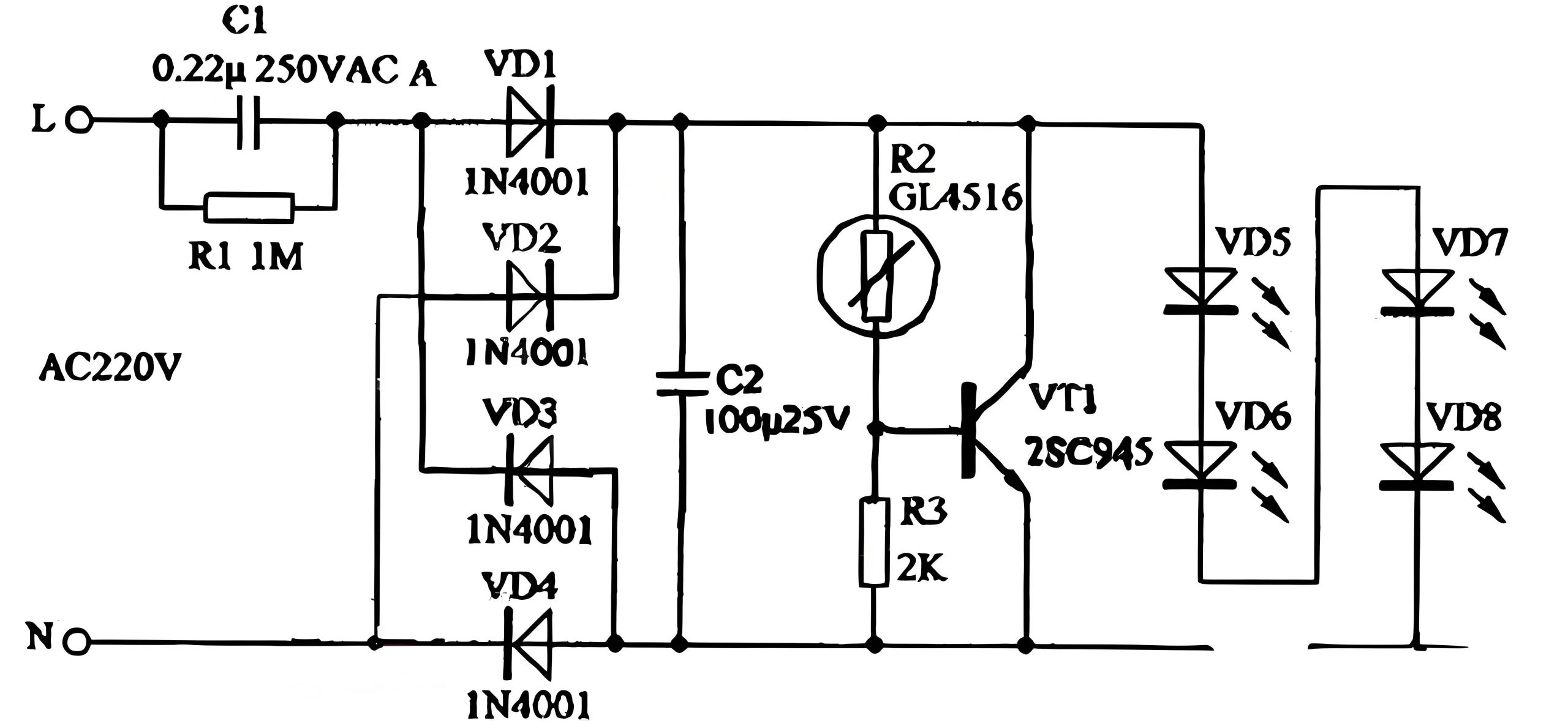
      The circuit structure of the ballast light is shown in the figure, which covers several key parts such as capacitor step-down circuit, rectifier circuit, LED light-emitting circuit and photoelectric control circuit. These circuits work together to ensure that the LED light can emit light stably and efficiently.

      A typical light ballast PCB diagram shows both input and output sides, along with key components like capacitors, inductors, and switching transistors.

      At the input stage, a fuse and filter block unwanted noise from the power source. Next, a rectifier converts AC to DC, which passes through smoothing capacitors to create stable voltage. The control section uses a micro-controller or driver IC to regulate switching transistors. These transistors adjust voltage and frequency, ensuring the lamp gets the right current flow. The output stage includes the final filter and connections to the lamp. In fluorescent lamps, this stage also includes a high-voltage starter circuit.

      Overall, the diagram reflects a balance between power conversion, current control, and protection, all packed into a compact PCB layout.

      Application of light ballast on PCB

      Light ballast PCBs appear in many everyday products and systems.

      • Kitchen lights, bathroom fixtures, and under-cabinet fluorescent lamps at home.
      • Ceiling panels, emergency lights, and retail display lamps in offices.
      • High-output lighting systems used for work areas, safety zones, and storage spaces in factories and warehouses.
      • Streetlights, parking lot lamps, stadium floodlights, and more. As outdoor lighting shifts to LED, many ballasts also act as LED drivers, offering advanced dimming and color control.
      • Growing application relates to recycling programs. Old ballasts, especially PCB fluorescent light ballasts, need careful handling due to environmental rules. Proper pcbs ballast recycling helps recover valuable metals while safely disposing of any hazardous materials.

      FAQ light ballast PCB

      • Aging of electronic components‌: Electronic components in light ballast power supplies, such as resistors, capacitors, diodes, transistors, etc., may age due to open circuits, short circuits, burnouts, leakage, functional failures, etc. during long-term use.
      • PCB quality impact: The quality of printed circuit boards (PCBs) and printed circuit board assemblies (PCBA) directly affects the reliability of LED driver power supplies. Problems such as poor wetting, board explosion, delamination, CAF (anode foil fiberization), open circuits, short circuits, etc. may cause power supply failure.
      • Heat dissipation problem‌: The electronic components in the light ballast PCB are very sensitive to temperature changes, especially the electrolytic capacitors. Poor heat dissipation may shorten the life of the components, thus affecting the stability of the LED lamps.
      • Solder joint failure: Solder joints are the key connection between electronic components and PCB boards, and their quality directly affects the reliability of the power supply. Solder joint failure may be caused by welding problems during the production process, or thermal stress fatigue caused by differences in thermal expansion coefficients.
      • Other issues: If the substrate hole is too large, the solder furnace temperature is too low, the board surface is poorly solderable, the solder mask is invalid, the board surface is contaminated, etc., it will also cause PCB problems.‌‌

      Conclusion
      The light ballast PCB plays a quiet but critical role in modern lighting systems. By delivering stable, efficient power, it protects lamps, saves energy, and supports advanced lighting controls. Whether you need simple fluorescent support or advanced smart lighting, the right light ballast PCB keeps your system running smoothly.

      You may also like

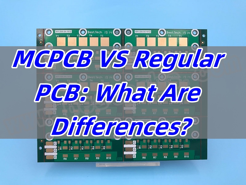
      MCPCB VS Regular PCB: What Are Differences?

      March 4th, 2025

      MCPCB VS Regular PCB is a topic many engineers and buyers search when choosing the right board for a project. Each type has clear benefits depending on the application, environment, and performance needs. Choosing between them needs more than just looking at the price. It also depends on thermal needs, material selection, and the product’s lifespan.

      In this blog, we’ll explore the core differences between MCPCB VS Regular PCB, focusing on materials, design, thermal resistance, and common applications. We’ll also highlight why metal core boards have become more popular for LED lighting and other heat-sensitive uses.

      MCPCB VS Regular PCB: What Are Differences?

      What is the most basic circuit board?

      The most basic circuit board used today is the FR4 PCB. FR4 refers to the fiberglass-reinforced epoxy laminate used as the core. This type of board acts as a solid foundation for electrical components. It supports the copper traces that carry signals across the board. FR4 has been the industry standard for decades due to its balanced electrical, mechanical, and thermal properties.

      Most everyday electronics, from home appliances to industrial equipment, rely on FR4 PCBs because of their low cost, stable structure, and easy processing.

      What is MCPCB?

      MCPCB stands for Metal Core Printed Circuit Board. Instead of a fiberglass base, these boards use a metal core layer, usually aluminum or copper. This design helps the board handle high heat better than regular FR4 boards.

      In MCPCB design, the metal core sits under the circuit layers. It helps pull heat away from hot components like LEDs or power transistors. This cooling method reduces the chance of overheating, extending the life of the whole board. MCPCB LED applications are some of the most common, especially in automotive, industrial, and high-power LED lighting.

      What is the material of MCPCB?

      The core material used in MCPCB design is usually aluminum or copper. Aluminum is more common due to its good heat conductivity and affordable cost. It balances performance and price, making it a top choice for MCPCB LED boards.

      Copper has higher thermal conductivity, but its cost is much higher. That’s why copper-core MCPCBs are mainly found in high-end equipment or where heat management is critical. On top of the metal core, dielectric layers provide electrical insulation and guide heat to the core. Copper traces on top complete the circuit.

      Why is FR4 used in PCB?

      FR4 remains popular in regular FR4 PCBs for many reasons. It has good mechanical strength, supports multi-layer designs, and offers decent thermal stability for common electronics. It also resists moisture well, making it reliable in humid environments.

      Another reason FR4 PCBs are used widely is their low manufacturing cost. They work well for low-power circuits where high heat dissipation isn’t a serious issue. For most general electronics, FR4 boards provide all the needed performance at a low price.

      MCPCB VS Regular PCB: What Are Differences?

      What are the thermal issues with PCB?

      Regular FR4 PCBs struggle when components produce high heat. Since fiberglass does not spread heat well, hot spots form near high-power parts. Over time, this localized heat can damage components, weaken solder joints, or deform the board itself.

      This thermal problem becomes more serious in high-density layouts where heat has nowhere to escape. That’s why high-power LED lighting, power converters, and some automotive systems have switched to MCPCB design.

      What is the thermal resistance of MCPCB?

      MCPCB thermal resistance is much lower than regular PCBs. This low resistance means heat can move through the board faster, keeping temperatures under control.

      In a well-designed MCPCB, heat moves directly from the component through the dielectric layer into the metal core, where it spreads across a larger area. This process reduces hot spots, protects components, and extends the product’s lifespan. Compared to regular FR4 boards, MCPCBs handle thermal stress far better.

      What are the uses of MCPCB?

      MCPCB design works best for products where heat dissipation matters most. Common uses include:

      High-power LED lighting, especially in automotive headlights and streetlights.

      Power supplies where voltage conversion creates heat.

      Solar inverters, handling high current and constant power flow.

      Telecom equipment, where stable performance under heat matters.

      Automotive control systems, especially in engine bays.

      Because of their thermal handling skills, MCPCB LED boards are some of the most common in today’s market.

      What are the advantages of metal core PCB?

      MCPCB design offers many advantages over regular PCBs. They include:

      Superior heat management, extending product life.

      Better mechanical strength, reducing vibration damage.

      Compact layouts, reducing weight and size.

      Reliable thermal paths, protecting sensitive parts.

      Stronger durability in tough environments.

      For projects where heat is a real issue, MCPCBs provide solutions that FR4 PCBs cannot match.

      What are the disadvantages of PCB?

      While FR4 PCBs work well for many products, they do have some limits in high-heat conditions. These boards:

      Do not spread heat well, leading to hot spots.

      May soften under high heat, reducing long-term stability.

      Offer weaker thermal paths, limiting high-power designs.

      However, for low-power and general devices, FR4 PCBs still provide affordable, reliable performance.

      What is the difference between FR4 and MCPCB?

      When comparing MCPCB VS Regular PCB, What are Differences? The biggest difference comes down to thermal performance. MCPCBs use metal cores, usually aluminum or copper, to spread heat faster and protect components.

      Regular FR4 PCBs rely on fiberglass, which does not move heat well. This makes them better for low-power circuits, where thermal buildup is not a concern.

      Cost is another difference. FR4 PCBs cost less to produce, especially in mass production. But for products where heat is a risk, spending more on MCPCB design reduces failure rates, protects components, and lowers maintenance costs.

      In short, MCPCB VS Regular PCB is not just about cost. It’s about matching the board to the product’s real-world needs.

      MCPCB VS Regular PCB: What Are Differences?

      In a nutshell, in the world of MCPCB VS Regular PCB, there’s no one-size-fits-all answer. FR4 PCBs remain the first choice for low-power electronics due to their low cost and easy manufacturing process. But when heat handling matters, especially for LED lighting, power electronics, or automotive systems, MCPCB design offers the best protection.

      At EBest Circuit (Best Technology), we specialize in custom MCPCB design, high-quality FR4 PCBs, and tailored thermal solutions. With over 18 years of experience, we help customers select the right PCB for each project. Whether you need reliable FR4 boards or advanced metal core solutions, our team provides fast support, expert advice, and global delivery. Please feel free to reach out to EBest Circuit (Best Technology) at sales@bestpcbs.com for your needs related to MCPCB and regular PCB. ‌

      You may also like

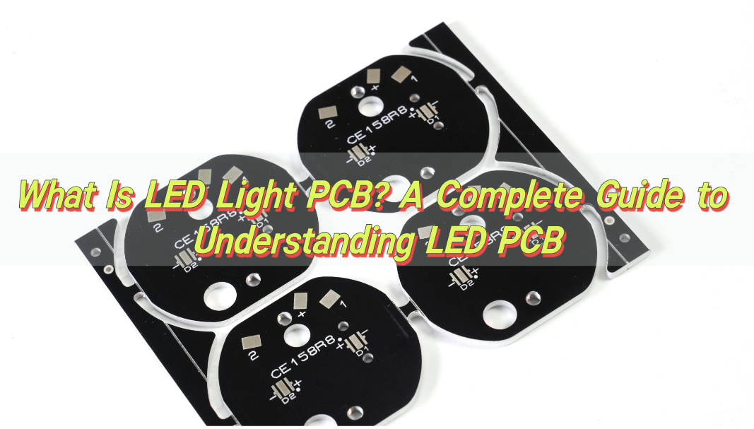
      What Is LED Light PCB? A Complete Guide to LED PCB

      February 27th, 2025


      LED light PCB has become an essential part of modern lighting technology. Whether you’re designing a sleek LED light strip or a high-powered LED bulb, understanding the structure and functionality of LED PCB is vital. In this blog, EBest Circuit (Best Technology) will dive deep into what makes LED light PCB, and the materials involved, their components, and the different types that suit various applications. By the end, you’ll have a clear understanding of LED PCB design, including how to connect LED to your custom board.

      What Is LED Light PCB? A Complete Guide to LED PCB

      What Is PCB in LED Light?

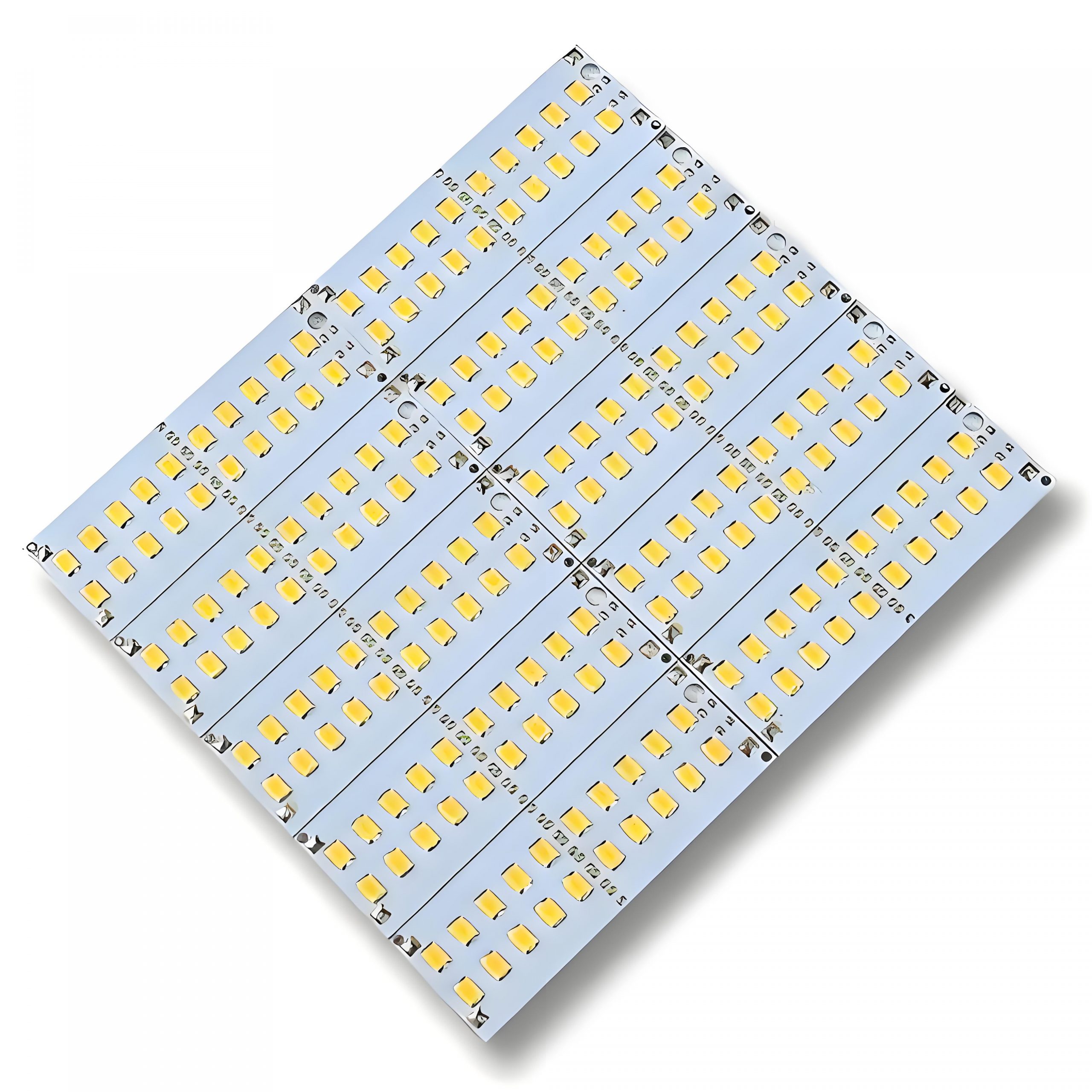
      A PCB (Printed Circuit Board) in an LED light is the base where all the components of the LED circuit are mounted. This board serves as the electrical pathway that connects the individual LED chips, allowing electricity to flow through the circuit and power the LED. The design of the PCB is crucial for managing heat dissipation, ensuring optimal light output, and maintaining energy efficiency. Aluminum LED light PCB, in particular, offer excellent thermal conductivity, which is essential in preventing overheating and extending the life of LED components.

      What Materials Are Used in LED PCB?

      LED PCB are made using several materials that work together to ensure optimal performance. The most common materials include:

      • Aluminum: Known for its high thermal conductivity, aluminum is often used in LED PCB to quickly dissipate heat. This is especially important in high-power LED applications.
      • Copper: Copper is used for its excellent electrical conductivity, ensuring that current flows efficiently through the PCB.
      • FR4 (Flame Retardant 4): This is a widely used epoxy resin laminate material that offers a good balance between electrical insulation and mechanical strength.
      • Ceramic: In some high-performance designs, ceramic-based PCB are used, particularly when superior heat resistance is required.
      What Is LED Light PCB? A Complete Guide to LED PCB

      Each material plays a specific role in enhancing the performance of the LED, from heat management to electrical conductivity.

      What Are the Components of LED PCB?

      LED PCB typically consist of the following components:

      • LED Chips: These are the tiny light-emitting diodes that convert electrical energy into light. They are usually placed on the surface of the PCB.
      • Copper Traces: These traces act as pathways for the electrical current, connecting the LED chips to each other and the power source.
      • Thermal Management Elements: In high-power applications, components like heat sinks and through-holes are included to help dissipate heat and maintain efficiency.
      • Resistors: These components control the flow of current through the LEDs to ensure they operate within their rated power limits.
      • Capacitors: Capacitors help smooth out fluctuations in voltage, providing stable power to the LED.
      What Is LED Light PCB? A Complete Guide to LED PCB

      Each component is crucial in ensuring the LED PCB works efficiently and has a long lifespan.

      What Are the Different Types of LED PCB?

      LED PCB come in several types, each designed to meet the needs of different applications:

      • Aluminum LED PCB: Aluminum LED PCB: As mentioned earlier, aluminum is widely used for its excellent heat dissipation. This type of PCB is ideal for high-power LED, like those used in lighting and automotive applications.
      • Flexible LED PCB:These PCB are made from flexible materials, allowing them to be bent and shaped for unique or custom designs. Flexible PCB are perfect for applications like LED strips and curved lighting solutions.
      • High-Density Interconnector(HDI PCB):These are used for applications requiring a higher level of integration, such as miniaturized LED systems.
      • Rigid LED PCB: These are made from solid, non-flexible materials and are commonly used in applications where the PCB will remain in a fixed position, such as in LED bulbs or signage.

      Each type of LED PCB is designed with specific characteristics in mind, such as flexibility, heat management, and power handling.

      How to Make LED PCB?

      Making an LED PCB involves several steps, from design to fabrication. Here’s an overview of the process:

      1. Design: First, you need to design the layout of your PCB. This includes selecting the components, determining the size and shape of the board, and creating the electrical connections between the components. CAD (Computer-Aided Design) software is typically used to create the design.

      2. Material Selection: Based on the design, select the appropriate PCB material (aluminum, copper, FR4, etc.) that meets your thermal, electrical, and mechanical needs.

      3. Printing the PCB: The design is transferred onto the PCB material using a photolithography process. This process involves applying a light-sensitive film to the board, exposing it to UV light, and then developing it to create the desired pattern of copper traces.

      4. Component Placement and Soldering: After the PCB is created, the LED chips, resistors, capacitors, and other components are placed on the board. Soldering techniques, such as Surface Mount Technology (SMT) or Through-Hole Technology (THT), are used to attach the components securely.

      5. Testing: Once the PCB is assembled, it’s tested for functionality. This involves checking the LED performance, ensuring the power distribution is correct, and verifying that the board is free from defects.

      How to Connect LED in PCB?

      Connecting LED to a PCB involves placing the LED components in the correct positions on the board and ensuring the electrical connections are made properly. Here are the steps to connect LED in a PCB:

      1. Design the Circuit: Determine the number of LED you’ll use, their configuration (series or parallel), and the required power. This will dictate the placement and size of the copper traces on the PCB.
      2. Place the LED: LED are usually mounted on the PCB using soldering methods. For SMD (Surface-Mounted Device) LED, they are placed directly onto the surface of the PCB, while through-hole LED are placed through the holes of the PCB.
      3. Solder the Connections: Soldering is the method used to establish electrical connections between the LED leads and the copper traces. For high-density applications, automated soldering techniques are often used to ensure precision.
      4. Ensure Proper Heat Dissipation: Since LED generate heat during operation, it’s important to make sure the PCB design incorporates adequate thermal management, such as through-holes, heat sinks, and the right choice of materials.

      Properly connecting LED ensures optimal performance, longevity, and safety for the final product.

      Conclusion

      LED light PCB are a game-changer in the world of lighting technology. From high-power lighting systems to sleek LED strips, these PCB offer exceptional performance, heat management, and reliability. Whether you’re designing a custom LED PCB or working with a manufacturer, understanding the components, materials, and types of LED PCB is essential to achieving the best results.

      By selecting the right PCB type, using quality materials, and ensuring proper design and assembly, you can create LED systems that are efficient, durable, and energy-efficient. If you’re ready to bring your LED projects to life, partnering with a reliable LED PCB manufacturer is the next step toward achieving the perfect lighting solution for your needs.

      Call to Action

      Ready to design your own LED light PCB? Contact EBest Circuit (Best Technology) at sales@bestpcbs.com today to learn about our custom PCB solutions, from aluminum LED light PCB to flexible LED strips. Let us help you make the prefect pcb with your next project! Looking forward to hearing from you!

      You may also like

      What Is LED Polarity and Why Does It Matter?

      February 17th, 2025

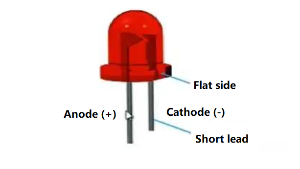
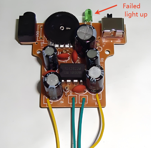
      What Is LED Polarity and Why Does It Matter? LED polarity is one of the most important things to understand when working with LEDs, especilly in PCB assembly. A wrong LED polarity put will cause the failure of the PCB product. Unlike regular bulbs, LEDs only work if they are connected the right way. If you mix up the positive and negative sides, the LED won’t light up. So, whether you’re building a simple LED circuit, installing LED light strips, or working with surface-mount LEDs, understanding LED polarity helps prevent issues. In this guide, we’ll answer the most common questions about LED polarity and explain how to identify and test LED connections correctly.

      What Is LED Polarity and Why Does It Matter?

      What Is LED Polarity?

      LED polarity refers to the direction in which an LED must be connected to a power source. Since LEDs are diodes, they allow current to flow in only one direction. This means that one leg of the LED must be connected to the positive side of the power supply, while the other must go to the negative side.

      Each LED has two legs:

      • Anode (+): This is the positive leg. It needs to be connected to the positive terminal of the power source.
      • Cathode (-): This is the negative leg. It must connect to the negative terminal.

      If the LED is wired incorrectly, it won’t light up because no current will flow through it. Some LEDs may even get damaged if too much voltage is applied in the wrong direction.

      Do LEDs Have Polarity?

      Yes, LEDs have polarity, and they must be connected correctly to function. Unlike traditional incandescent bulbs that work regardless of connection direction, LEDs only operate when the anode is connected to the positive voltage and the cathode to the ground.

      The reason for this is that LEDs are light-emitting diodes. Diodes are semiconductor components that allow current to pass in one direction while blocking it in the other. When you reverse the polarity of an LED, it stops conducting electricity, which means it won’t produce light.

      LED Polarity Symbol

      If you look at circuit diagrams, you’ll notice a special symbol used for LEDs. The LED polarity symbol is similar to a regular diode symbol but has two arrows pointing away from it to indicate light emission. Below are the common led polarity symbols used in the industry:

      What Is LED Polarity and Why Does It Matter?

      Are LED Light Bulbs Polarity Sensitive?

      It depends on the type of LED light bulb.

      • AC-powered LED bulbs (like household LED light bulbs) are usually not polarity sensitive because they contain internal rectifiers that convert AC to DC.
      • DC-powered LEDs (such as those used in automotive applications, flashlights, or indicator lights) are polarity sensitive and will not work if connected incorrectly.

      When working with DC-powered LED systems, checking the wiring is crucial. Many LED strips and car LEDs have markings to indicate which side should connect to positive and which should go to negative.

      How Do You Identify the Polarity of an LED?

      There are several ways to determine LED polarity:

      1. Check the Lead Length

      If it has leds, check the lead length is the most important method to identify:

      • The longer lead is the anode (+).
      • The shorter lead is the cathode (-).
      What Is LED Polarity and Why Does It Matter?

      This method works well for new LEDs, but if the leads are trimmed, other methods may be needed.

      2. Look for a Flat Edge

      On many through-hole LEDs, the cathode side has a flat edge on the plastic casing. This marking helps quickly identify polarity. (Please refer above images of LED).

      3. Inspect the Internal Structure

      If you have a clear LED, you can look inside:

      • The larger internal piece is usually the cathode (-).
      • The smaller piece is the anode (+).

      This method works well for transparent or diffused LEDs but is harder for small surface-mount LEDs.

      4. Use a Multimeter

      A digital multimeter with a diode test function can confirm polarity. When the red probe touches the anode and the black probe touches the cathode, the LED will glow slightly or show a voltage reading. If no reading appears, reverse the probes.

      What Happens If LED Polarity Is Reversed?

      If the LED is connected backward, it won’t light up. Unlike incandescent bulbs, which work in either direction, LEDs only allow current to flow in one way. Here are some common issues if LED polarity is reversed:

      1. No Light Emission: Since LEDs are polarized components, they only work when connected correctly. If the polarity is reversed, current cannot flow, and the LED will not light up.

      What Is LED Polarity and Why Does It Matter?

      2. Potential Damage: In some cases, a reversed connection may cause damage. Excessive reverse voltage or current can harm the internal structure of the LED.

      3. Overheating: Incorrect polarity may lead to improper current flow, generating excess heat. This can affect both the LED and nearby circuit components.

      4. Short Circuit Risk: A severe polarity reversal could create a short circuit, which may harm the power source or other connected components.

      5. Unstable Lighting: In rare cases, an incorrectly wired LED may flicker or dim unpredictably instead of staying off completely.

      In most cases, a reversed LED will not get damaged unless the voltage is too high. However, some circuits use protection resistors or diodes to prevent issues caused by incorrect polarity.

      Does LED Polarity Matter?

      Yes, LED polarity matters because LEDs are diodes that function only when connected correctly. If you ignore polarity, the LED won’t work. In some cases, incorrect wiring can cause damage, especially in high-power LEDs or integrated circuits.

      To avoid problems:

      • Always check the polarity markings before connecting an LED.
      • Use a multimeter if unsure.
      • Follow circuit diagrams carefully.

      How to Check an LED with a Multimeter?

      Using a multimeter is one of the easiest ways to test an LED’s polarity and functionality. Here’s a step-by-step guide:

      1. Set the Multimeter to Diode Test Mode

      Most digital multimeters have a diode test mode, usually marked with a diode symbol (a triangle pointing to a line). If your multimeter doesn’t have this mode, use the resistance (Ω) setting on the lowest range.

      2. Identify the Probes

      • The red probe is the positive (+) lead.
      • The black probe is the negative (-) lead.

      3. Connect the Probes to the LED Legs

      Touch the red probe to one leg and the black probe to the other.

      • If the LED lights up faintly or shows a voltage reading (typically 1.8V to 3.5V, depending on the LED type), the red probe is on the anode (+), and the black probe is on the cathode (-).
      • If nothing happens, swap the probes and try again.

      4. Interpret the Results

      • If the LED lights up, it means it is working, and you have identified the correct polarity.
      • If the LED doesn’t light up in either direction, it may be faulty or burned out.
      • If using the resistance mode, a working LED will show a resistance value in one direction and an infinite resistance (OL) in the other.

      5. Testing Surface-Mount LEDs (SMD LEDs)

      Since SMD LEDs are small and lack long leads, identifying polarity can be tricky. Many have a small marking on the cathode side. To test them:

      • Use fine-tip multimeter probes.
      • Hold the probes gently on the pads.
      • Observe if the LED lights up or if a voltage reading appears.

      A multimeter is a quick and reliable tool to check LED polarity before installing it in a circuit.

      Which Side of the LED Should You Put a Resistor?

      A resistor is needed to control current flow and protect the LED. The resistor can go on either side of the LED—anode or cathode—without affecting polarity. However, placing it on the anode side (+) is common for consistency in circuit designs.

      Without a resistor, the LED might receive too much current, which could shorten its lifespan or cause it to burn out.

      FAQs

      1. Can LED polarity be ignored?

      No, LED polarity is essential for proper operation. If wired incorrectly, the LED will not work.

      2. Do surface-mount LEDs have polarity?

      Yes, surface-mount LEDs have polarity. Manufacturers usually mark the cathode with a dot or a line.

      3. What happens if an LED is connected to AC power?

      An LED without a rectifier will flicker or not work properly on AC power. A rectifier or resistor is needed for AC operation.

      4. How do I fix a reversed LED?

      Simply swap the connections. If the LED hasn’t been damaged, it should work fine.

      5. Why do some LEDs have built-in resistors?

      Built-in resistors simplify wiring by ensuring safe current levels. These LEDs can be directly connected to power sources without extra components.

      You may also like

      Can I design microvias in multilayer MCPCB?

      October 12th, 2024

      What is a Microvias?

      A microvia is a small hole drilled into a PCB that connects different layers. They are essential for high-density interconnections and are commonly used in advanced electronic designs. Typically, microvias equal to or less than 150 microns drilled on the PCB board with a laser. In 2013, the IPC standard changed the definition of microvias to those with an aspect ratio of 1:1. Ratio of aperture to depth (not exceeding 0.25mm). Previously, micropores were less than or equal to 0.15 mm in diameter, so they typically spanned only one layer.

      Can I design microvias in multilayer MCPCB?

      Because the diameter is very small compared to mechanically drilled through holes (PTH), we define them as microvias, usually connecting only one layer of the board to its adjacent layers. These through holes reduce the possibility of any type of manufacturing defect because they are laser drilled, thus reducing the possibility of any residue remaining after the process. Because of their small size and ability to connect one layer to the next, they can make dense printed circuit boards with more complex designs.

      Types of Microvias

      There are two types of microvias in the PCB design – stacked microvias and staggered microvias.

      • Stacked Microvias

      Stacked microvias are formed by stacking multiple layers on top of each other to provide a path through which current flows. Create a hole in one layer and drill into another layer below. The top layer is welded or welded to the bottom layer to form an interconnect between the two layers. This allows for fast, efficient routing without compromising performance or reliability.

      Can I design microvias in multilayer MCPCB?
      • Staggered Microvias

      The interlaced microvias is aligned with the pad of the same layer, but is offset from its center by half of the pad diameter. The distance from its center to the edge of the board is also half the diameter of the pad. Staggered microvias allow you to place two through holes in a single pad without overlapping them or having to route wires on different layers together in this location. This type of microvias can be used for electrical connections to the surrounding brass pads and traces.

      Can I design microvias in multilayer MCPCB?

      What is the Difference Between Vias and Microvias?

      Vias and microvias serve similar purposes in connecting different layers of a PCB, but they differ significantly in size and application.

      1. Size

      One of the most significant differences between vias and microvias is their size. Standard vias typically have a diameter greater than 150 micrometers (ÎŒm), while microvias are defined as having a diameter of 150 ÎŒm or less.

      2. Design Complexity

      As technology advances, the demand for higher circuit densities and more complex designs has grown. Microvias enable designers to create intricate multilayer circuits that were not possible with standard vias.

      3. Layer Connection

      Standard vias can connect any number of layers in a PCB, typically running from the outer layer through to the inner layers. In contrast, microvias are usually used for connecting one or two layers. Microvias are commonly employed in multilayer PCBs, where they can connect the outer layer to one or more inner layers without passing through the entire board.

      4. Aspect Ratio

      The aspect ratio, which is the ratio of the depth of a via to its diameter, is another important difference. Standard vias generally have lower aspect ratios, making them easier to fabricate. Microvias, due to their smaller size, often have higher aspect ratios. A typical aspect ratio for microvias ranges from 1:1 to 2:1.

      5. Applications

      Standard vias are commonly used in traditional PCB designs for applications where space is not as critical. They are suitable for general-purpose circuits, power distribution, and less complex layouts. In contrast, microvias are essential in high-density applications, such as smartphones, tablets, and advanced computing devices, where compact designs are necessary.

      Microvias vs. Blind Via

      Blind vias connect the outer layer of the PCB to one or more inner layers without penetrating the entire board. As the name suggests, these through-holes are “blind holes” because they are not visible from the other side of the PCB. Blind holes have several advantages, such as saving space on the board, enabling a more compact design, and improving signal integrity by reducing the length of the signal path.

      The blind via passes through the surface layer of the PCB, extending through only a portion of the board to connect the surface layer to one or more inner layers. They are a key component in current PCB designs, allowing surface components to connect to inner layers while minimizing the number of layers required for wiring. The advantages of using blind vias including:

      • Increased density
      • Reduce the number of layers
      • Improved signal performance
      • Good for heat dissipation
      • Improve mechanical strength

      Can Microvias be Designed in Multilayer MCPCB?

      Yes, microvias can indeed be designed in multilayer MCPCBs. In fact, their small size and efficient design make them ideal for these types of boards. Multilayer MCPCBs often require compact interconnections to accommodate various functionalities, and microvias facilitate this need. By enabling multiple layers to connect efficiently, microvias enhance the overall performance of the MCPCB. Additionally, they contribute to improved thermal management, a critical factor in high-power applications. Their integration in multilayer designs is a significant advantage for modern electronics.

      The process for using microvias in multilayer metal-based circuit boards includes the following key steps:

      1. Inner laser drilling and plating: This is the first step in the production of microvias, precisely drilled by laser technology, and electroplated.

      2. Resin filled: The micro-vias after electroplating are filled with resin to enhance the stability of the structure.

      3. Resin grinding: Grind the orifice after the jack hole to ensure a smooth surface.

      4. Electroplating: Metallize the surface of the orifice resin to achieve electrical interconnection between layers.

      5. Inner circuit etching and outer layer lamination: To complete the production of the inner circuit, and the outer layer of laser drilling and graphic plating, and finally realize the production of multi-layer circuit board.

      MCPCB Material in EBest Circuit (Best Technology)

      Can I design microvias in multilayer MCPCB?

      MCPCB Prototype Lead Time (Vary Depends on the MCPCB Design)

      Can I design microvias in multilayer MCPCB?

      You may also like

      2 Layer Aluminum PCB | Metal Core PCB Manufacturer

      October 9th, 2024

      What is a 2 Layer Aluminum PCB?

      A 2-layer aluminum PCB is a type of metal core circuit board that contains two conductive layers, usually copper, with an aluminum core or base material. Aluminum PCBs are used for their excellent heat dissipation properties, and always used in high-power applications like LED lighting, power supplies, and automotive systems. The aluminum base offers better thermal management than standard FR4 PCBs. In a 2-layer aluminum PCB, the two conductive copper layers allow more complex routing for electrical signals compared to single-layer boards.

      2 Layer Aluminum PCB | Metal Core PCB Manufacturer

      2 Layer Aluminum PCB Stack-Up

      The stack-up of a 2-layer aluminum PCB consists of the following:

      • Top Copper Layer: This is where the signal traces and components are located. It can vary in thickness, depending on current-carrying requirements.
      • Dielectric Layer: A layer of insulation that separates the top copper layer from the aluminum core. It plays a key role in electrical isolation and heat transfer.
      • Aluminum Base: This core provides structural support and excellent heat dissipation properties. It also serves as the grounding plane in some designs.
      • Bottom Copper Layer: The second conductive layer allows for more advanced routing.
      2 Layer Aluminum PCB | Metal Core PCB Manufacturer

      How Thick is a 2 Layer PCB Layer?

      The thickness of a 2-layer aluminum PCB can vary depending on the specific design requirements, but typically, the copper layer is about 1 to 2 ounces (35 to 70 microns) thick. The aluminum base itself is thicker, usually between 1.0 mm and 3.0 mm, depending on the board’s required rigidity and heat dissipation needs. The overall board thickness generally ranges between 1.2 mm and 3.2 mm.

      A thicker aluminum core improves heat transfer, but the board’s thickness must also align with the product’s mechanical and electrical requirements. Designers often have to balance between sufficient thermal performance and the overall board size for practical applications.

      Is Thicker Aluminum PCB have Better Heat Dissipation?

      Generally speaking, the thinner the thickness of the aluminum PCB, the faster the heat conduction speed. The thicker the thickness of the aluminum PCB, the slower the heat conduction rate. The thermal conductivity of aluminum-based circuit board mainly depends on its material and structure. Although thickness affects the path length of heat conduction, the more critical factors are the thermal conductivity and structural design of the material. For example, high thermal conductivity materials such as copper, silver and other high thermal conductivity materials will significantly improve the thermal conductivity of aluminum substrate. In addition, the thickness and thermal conductivity of the insulation layer will also affect the overall thermal conductivity effect ‌.

      Specifically, the thermal conductivity of the aluminum-based circuit board is also related to the thickness of its insulation layer. The thicker the insulation layer, although it can withstand higher voltage, it will also reduce the heat transfer efficiency. Therefore, choosing the appropriate insulation layer thickness and materials with high thermal conductivity is the key to ensuring efficient thermal conductivity of aluminum-based circuit boards ‌.

      2 Layers Aluminum PCB vs. Double Sided Aluminum PCB

      Though the terms “2 layers aluminum PCB” and “double-sided aluminum PCB” might sound similar, there are slight differences.

      A 2-layer aluminum PCB contains two conductive copper layers. These layers can be arranged to handle signal routing and ground planes separately. In contrast, a double-sided aluminum PCB typically has one copper layer on either side of the aluminum core, offering less flexibility in routing. Here is the stack up of double sided aluminum PCB:

      2 Layer Aluminum PCB | Metal Core PCB Manufacturer

      How Much Does Aluminum PCB Cost?

      The cost of an aluminum PCB, including a 2-layer version, depends on several factors such as the board’s thickness, copper weight, design complexity, and production volume. On average, 2-layer aluminum PCBs cost more than single-sided aluminum PCBs because of the additional copper layer and routing complexity.

      For small orders, prices might range between $5 and $15 per square foot. For larger production runs, costs can decrease significantly due to economies of scale. Factors like the thickness of the aluminum base and copper layer, as well as additional features like surface finishes, can also influence the price.

      While aluminum PCBs are more expensive than standard FR4 boards, their enhanced thermal performance can reduce overall system costs by improving reliability and reducing the need for additional cooling measures.

      How Many Layers Should a PCB Have?

      The number of layers a PCB should have depends on the complexity of the design. For simple applications like LED lighting or power conversion, a 2-layer aluminum PCB is often sufficient. It provides more routing flexibility than a single-layer board while still offering effective heat dissipation.

      For more complex designs requiring high-density interconnections or additional functionality, a multi-layer PCB with three or more layers might be necessary. However, multi-layer aluminum PCBs are rare because their primary function is thermal management, which is typically solved within one or two layers. The decision to use more layers depends on the specific application, power requirements, and signal integrity needed in the design.

      Aluminum PCB Design Guidelines

      When designing a 2-layer aluminum PCB, several factors must be considered to maximize performance:

      • Thermal Management: Since aluminum PCBs are chosen for their thermal properties, optimizing heat dissipation is critical. Components that generate significant heat should be placed near the aluminum core, allowing for faster heat transfer.
      • Copper Thickness: The copper thickness should match the current-carrying requirements of the design. Using thicker copper can help manage higher current loads, but it also increases the cost and weight of the PCB.
      • Dielectric Layer: The thickness and material of the dielectric layer play a crucial role in both thermal and electrical performance. A thinner dielectric layer improves heat dissipation but may limit electrical isolation. Choosing the right dielectric material is key for balancing performance and reliability.
      • Via Placement: For a 2-layer design, vias must be carefully placed to connect the two copper layers. Vias should be positioned to minimize electrical interference and maintain signal integrity.
      • Component Placement: Heat-sensitive components should be placed away from high-power components. This minimizes thermal stress on sensitive devices and ensures reliable operation over the PCB’s lifespan.

      Aluminum PCBs may come with a higher price tag compared to traditional FR4 boards, but the long-term benefits in heat management, performance, and durability make them an excellent investment for demanding applications. Whether you’re working on power electronics, automotive circuits, or lighting solutions, a 2-layer aluminum PCB can provide the right balance between complexity and thermal efficiency.

      If you’re in need of high-quality, custom aluminum PCBs, EBest Circuit (Best Technology) specializes in delivering tailored solutions for your specific design needs. With 18+ years of experience in PCB manufacturing, we ensure top-notch performance, quality, and reliability for all your projects. Let us help you bring your ideas to life with the right aluminum PCB solution!

      You may also like