KB-6165F copper clad laminates are mid-Tg FR-4 materials engineered for lead-free PCB manufacturing, offering improved Anti-CAF reliability, stable dielectric performance, and enhanced thermal endurance.
In modern electronics, where multilayer complexity and environmental stress are constantly increasing, material selection has become a critical design variable. Choosing KB-6165F is not simply about meeting specifications—it is about reducing long-term failure risks, maintaining signal integrity, and ensuring consistent production yield.
This guide explores the material from an engineering perspective, covering performance characteristics, design considerations, and real manufacturing implications.
What Is KB-6165F Copper Clad Laminate?
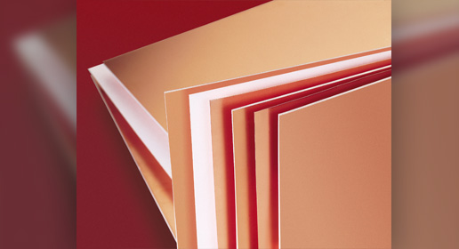
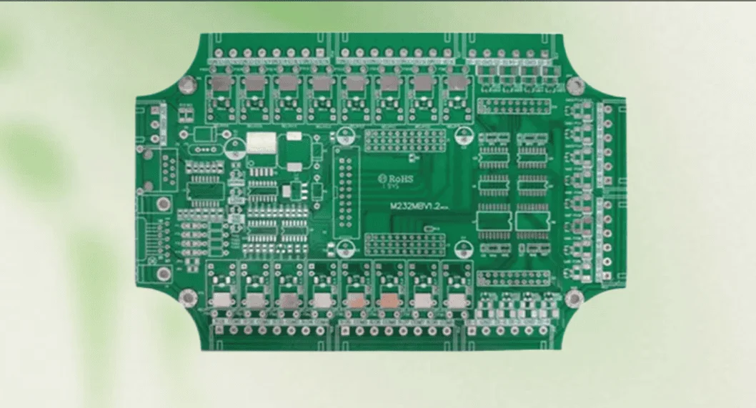
KB-6165F is a glass-reinforced epoxy laminate system developed to meet the growing demand for reliability in lead-free and high-density PCB designs. It belongs to the mid-Tg FR-4 category, positioned between conventional FR-4 and high-Tg materials.
From a structural standpoint, it consists of:
- Woven fiberglass reinforcement
- Epoxy resin system
- Copper foil layers bonded under heat and pressure
The result is a laminate that provides improved thermal stability and electrical insulation compared to standard FR-4.
What makes KB-6165F particularly relevant today is its ability to address two common challenges in PCB design:
- Thermal stress caused by repeated soldering cycles
- Insulation degradation due to CAF formation
Because of this, it is widely used in multilayer PCBs where reliability must be maintained over extended operational lifetimes.
What Are the Main Features of KB-6165F?
KB-6165F is designed to solve specific engineering problems rather than just improving baseline performance. Its features are best understood in terms of how they influence real-world PCB behavior.
Mid-Tg Thermal Stability
The glass transition temperature of approximately 150–157°C allows the material to remain mechanically stable during lead-free soldering. This reduces internal stress and minimizes deformation during thermal cycling.
Enhanced Anti-CAF Capability
CAF is a failure mechanism that occurs under voltage and humidity conditions, leading to conductive paths forming between vias. KB-6165F uses a refined resin system that significantly improves resistance to this phenomenon, extending insulation reliability.
Lead-Free Process Compatibility
Lead-free assembly processes operate at higher temperatures than traditional soldering. KB-6165F maintains structural integrity under these conditions, ensuring that multilayer bonding remains stable.
Dimensional Stability
In multilayer PCB fabrication, maintaining precise dimensions is critical for alignment and impedance control. KB-6165F provides stable expansion characteristics, helping reduce registration errors.
Balanced Cost Efficiency
While it offers improved reliability compared to standard FR-4, it remains cost-effective compared to high-Tg or specialty materials. This makes it suitable for large-scale production without excessive cost increase.
KB-6165F Datasheet Overview
Understanding material properties is essential for engineering decisions. The following table summarizes typical characteristics:
| Property | Typical Value | Test Method / Notes |
| Material Type | FR-4 Epoxy Glass Laminate | Woven fiberglass + epoxy resin |
| Standard Compliance | IPC-4101 /99 /101 | Depending on version |
| UL Rating | UL94 V-0 | Flame retardant |
| Compatible Prepreg | KB-6065F | Matching system |
| Tg (DSC) | 150–157°C | Differential Scanning Calorimetry |
| Tg (TMA) | ~140–150°C | Thermomechanical Analysis |
| Td (5% weight loss) | >300°C | Thermal decomposition |
| Z-axis CTE (<Tg) | ~50–70 ppm/°C | Thickness direction |
| Z-axis CTE (>Tg) | ~250–300 ppm/°C | Above Tg expansion |
| Thermal Conductivity | ~0.3–0.4 W/m·K | Typical FR-4 level |
| Dielectric Constant (Dk @1GHz) | 4.2 – 4.5 | Frequency dependent |
| Dissipation Factor (Df @1GHz) | 0.018 – 0.022 | Loss performance |
| Surface Resistivity | ≥10⁶ MΩ | High insulation |
| Volume Resistivity | ≥10⁷ MΩ·cm | Insulation reliability |
| Dielectric Breakdown | ≥40 kV/mm | High voltage tolerance |
| CTI (Comparative Tracking Index) | ~175V | IEC standard |
| Flexural Strength (MD) | ≥400 MPa | Machine direction |
| Flexural Strength (CD) | ≥300 MPa | Cross direction |
| Peel Strength (1 oz Cu) | ≥1.0 N/mm | After thermal stress |
| Density | ~1.85 g/cm³ | Typical |
| Moisture Absorption | ≤0.15% | 24h immersion |
| CAF Resistance | High (Anti-CAF) | Improved resin system |
| Ionic Contamination Resistance | Good | Long-term reliability |
| Lead-Free Compatibility | Yes | Multiple reflow cycles |
| Lamination Temperature | ~170–185°C | Typical press profile |
| Drillability | Good | Clean hole walls |
| Plating Adhesion | Excellent | Strong copper bonding |
From an engineering perspective, KB-6165F copper clad laminates provide a balanced combination of thermal endurance, electrical insulation, and manufacturing stability. The mid-Tg property helps the board withstand lead-free soldering, while the Anti-CAF performance supports better reliability in dense multilayer PCB designs.
When reviewing the KB-6165F datasheet, engineers should pay close attention to Tg, Td, Z-axis CTE, Dk, Df, CTI, and moisture absorption. These parameters directly affect PCB lamination quality, via reliability, impedance stability, and long-term field performance.
From an electrical standpoint, the dielectric properties make it suitable for general-purpose and moderate-speed signal applications. From a thermal standpoint, the high decomposition temperature ensures durability during manufacturing and operation.
Why Is KB-6165F Suitable for Lead-Free PCB Manufacturing?
Lead-free soldering has significantly increased thermal stress on PCB materials. Peak temperatures often reach 245–260°C, which challenges traditional FR-4 laminates.
KB-6165F addresses these challenges through multiple mechanisms:
Thermal Margin Improvement
The higher Tg ensures that the material remains below its glass transition point for a longer duration during heating cycles, reducing mechanical deformation.
Improved Resin Integrity
The epoxy system is formulated to resist breakdown under high temperatures, maintaining bonding strength between layers.
Reduced Moisture-Induced Stress
Moisture trapped in the laminate can expand rapidly during reflow, causing delamination or micro-cracks. KB-6165F has lower moisture absorption, reducing this risk.
Manufacturing Outcome
For PCB manufacturers, these properties result in:
- Fewer delamination defects
- Lower warpage rates
- Higher assembly yield
What Is the Difference Between KB-6165F and Standard FR-4?
Choosing between materials often comes down to application requirements. While both are FR-4 based, their performance differs significantly.
| Feature | Standard FR-4 | KB-6165F |
|---|---|---|
| Tg | ~130–140°C | ~150–157°C |
| Thermal Stability | Moderate | Improved |
| CAF Resistance | Basic | Enhanced |
| Reliability Level | General use | High-reliability |
| Moisture Resistance | Moderate | Better |
| Cost | Lower | Slightly higher |
From a design perspective, KB-6165F is preferred when:
- The PCB operates in humid or high-voltage environments
- Long-term reliability is critical
- Multilayer complexity increases
What Is KB-6065F Prepreg?
Prepreg plays a critical role in multilayer PCB construction. KB-6065F is specifically designed to work with KB-6165F laminates.
During lamination:
- Heat and pressure activate the resin
- Layers bond together into a unified structure
Using a matched prepreg ensures:
- Consistent thermal expansion
- Uniform dielectric properties
- Strong interlayer adhesion
Mismatched materials can introduce internal stress, leading to long-term reliability issues. Therefore, pairing KB-6165F with KB-6065F is a standard engineering practice.
Where Is KB-6165F Used in PCB Manufacturing?
KB-6165F is widely used in applications where reliability and cost balance are both important.
Typical application areas include:
- Industrial automation systems
- Automotive electronics
- Power supply boards
- Communication infrastructure
- Consumer electronics with extended service life
In terms of PCB structure, it is commonly used for:
- 4-layer to 12-layer boards
- Mixed-signal circuits
- Medium-density interconnect designs
KB-6165F for Automotive and Industrial PCBs
Automotive and industrial environments impose strict requirements on PCB materials. These include exposure to temperature cycling, humidity, and electrical stress.
KB-6165F performs well in these conditions due to:
- Stable dielectric properties under temperature variation
- High insulation reliability through Anti-CAF design
- Strong resistance to thermal fatigue
Typical automotive applications include:
- Engine control units (ECUs)
- Power management systems
- Sensor interface modules
For industrial applications, it is used in:
- Motor control systems
- Power conversion equipment
- Industrial communication modules
How to Choose KB-6165F for Multilayer PCB Stackup?
Material selection should align with the electrical, thermal, and mechanical requirements of the design.
Key considerations include:
Layer Count
KB-6165F is well suited for mid-layer count designs, typically up to 12 layers.
Signal Performance
While not a high-frequency material, it supports stable impedance control for standard digital and mixed-signal circuits.
Thermal Environment
If the operating temperature is moderate but includes occasional peaks, KB-6165F provides sufficient margin.
Cost Efficiency
For projects requiring reliability without excessive material cost, it offers a practical solution.
KB-6165F PCB Manufacturing Considerations
Although similar to FR-4 in processing, KB-6165F requires careful control to achieve optimal performance.
Lamination Process
Accurate temperature and pressure control are necessary to fully cure the resin and ensure strong bonding.
Drilling and Via Quality
Smooth hole walls help reduce the risk of CAF formation and improve plating quality.
Moisture Management
Pre-baking before lamination or assembly is recommended to remove absorbed moisture.
Stackup Symmetry
Balanced stackups reduce warpage and improve mechanical stability.
KB-6165F Copper Clad Laminate at EBest PCB
At EBest PCB, KB-6165F is widely used in industrial-grade and automotive PCB production.
Our capabilities include:
- Material selection consulting during DFM stage
- Multilayer stackup optimization using KB-6165F and KB-6065F
- Impedance-controlled PCB fabrication
- Full traceability for high-reliability industries
With integrated PCB fabrication and assembly services, we help engineers reduce design risks and achieve consistent manufacturing results.
FAQs About KB-6165F Copper Clad Laminates
Is KB-6165F suitable for multilayer PCB?
Yes, it is specifically designed for multilayer applications, offering stable bonding and consistent dielectric performance.
Can KB-6165F replace standard FR-4?
In many cases, yes. It provides better reliability, especially in environments with thermal and humidity stress.
Is KB-6165F good for high-frequency design?
It is suitable for moderate-speed signals, but dedicated RF materials are recommended for high-frequency applications.
What prepreg should be used with KB-6165F?
KB-6065F prepreg is recommended for compatibility and performance consistency.
Does KB-6165F increase manufacturing complexity?
Not significantly. It can be processed using standard FR-4 fabrication techniques with proper control.
Conclusion
KB-6165F copper clad laminates offer a reliable and cost-effective solution for modern PCB designs that demand more than standard FR-4 can provide. Its mid-Tg performance, Anti-CAF capability, and compatibility with lead-free processes make it a strong candidate for industrial and automotive applications.
For engineers seeking stability without unnecessary cost escalation, KB-6165F provides a practical balance. It supports consistent multilayer construction, improves long-term reliability, and reduces manufacturing risks.
Looking for KB-6165F PCB manufacturing support?
Contact: sales@bestpcbs.com