

RO3003 PCB material is a precision-engineered high-frequency laminate developed by Rogers Corporation, designed for RF, microwave, and millimeter-wave circuit applications. Known in the industry as rogers ro3003, this material delivers ultra-stable dielectric performance, low loss, and excellent mechanical consistency, making it a preferred choice for demanding RF designs.
When evaluating ro3003 substrate, engineers typically focus on three critical aspects: dielectric stability, signal loss, and manufacturability. RO3003 addresses all three, which explains its widespread use in automotive radar, 5G infrastructure, and high-frequency communication systems.
RO3003™ PCB Material
What Is RO3003 Material?
RO3003 material is a ceramic-filled PTFE composite laminate, part of the RO3000 series. It is engineered to provide consistent electrical properties across frequency and temperature ranges, which is essential for RF circuit performance.
In practical engineering discussions, this material may also be referred to as:
- ro3003 rogers
- rogers ro3003 pcb
- rogers duroid ro3003
However, it is important to clarify that while “duroid” is sometimes used generically, rogers duroid ro3003 is not part of the RT/duroid family but belongs to the RO3000 series. Key material characteristics of Rogers RO3003:
- Non-woven ceramic-filled structure
- No glass fiber weave (reduces signal distortion)
- Extremely stable dielectric constant
- Low moisture absorption
- Compatible with high-frequency PCB fabrication
RO3003 Datasheet Overview
| Category | Property | Typical Value | Notes |
| Material Type | Base Material | Ceramic-filled PTFE | Stable ro3003 substrate for RF |
| Electrical Properties | RO3003 dielectric constant | 3.00 ± 0.04 @ 10 GHz | Also called rogers ro3003 dielectric constant |
| Design Dk | ~3.16 | Used for simulation | |
| RO3003 loss tangent | 0.0010 @ 10 GHz | Low loss RF performance | |
| Volume Resistivity | 10⁷ MΩ·cm | High insulation | |
| Surface Resistivity | 10⁷ MΩ | Reliable signal isolation | |
| Dielectric Breakdown | >31 kV/mm | Strong electrical strength | |
| Thermal Properties | Thermal Conductivity | 0.50 W/m·K | Helps heat dissipation |
| Tg (Glass Transition Temp) | N/A (PTFE-based) | No traditional Tg | |
| Thermal Coefficient of Dk | -3 ppm/°C | Excellent stability | |
| Decomposition Temperature (Td) | >500°C | High thermal endurance | |
| Mechanical Properties | Density | 2.1 g/cm³ | Higher than FR4 |
| Tensile Strength | ~200 MPa | Good mechanical strength | |
| Flexural Strength | ~150 MPa | Supports rigidity | |
| CTE (Thermal Expansion) | X-axis | 17 ppm/°C | Stable dimension |
| Y-axis | 16 ppm/°C | Balanced expansion | |
| Z-axis | 25 ppm/°C | Good via reliability | |
| Moisture & Safety | Water Absorption | 0.04% | Low moisture uptake |
| Flammability | UL94 V-0 | Meets safety standard | |
| Processing | Lead-Free Process | Compatible | Suitable for RoHS |
| RO3003 prepreg | Not standard | Use bonding film instead | |
| Thickness Options | RO3003 thickness | 5–60 mil (0.127–1.524 mm) | Also called rogers ro3003 thickness |
| Copper Foil | Copper Weight | 0.5 oz – 2 oz typical | Custom available |
| Cost Factors | RO3003 price | Higher than FR4 | Depends on thickness & volume |
RO3003 Dielectric Constant
The ro3003 dielectric constant is tightly controlled at 3.00, making it ideal for controlled impedance design.
Engineers often select rogers ro3003 dielectric constant when:
- impedance matching must remain stable across temperature
- phase consistency is required in RF networks
- signal integrity must be maintained at GHz frequencies
RO3003 Loss Tangent
The ro3003 loss tangent (0.0010) is considered very low, which helps reduce:
- insertion loss
- signal attenuation
- heat generation in RF traces
This makes ro3003 pcb suitable for high-frequency circuits where even small losses can affect system performance.
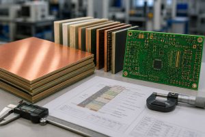
RO3003 Thickness Options
The available ro3003 thickness and rogers ro3003 thickness typically include:
- 5 mil (0.127 mm)
- 10 mil (0.254 mm)
- 20 mil (0.508 mm)
- 30 mil (0.762 mm)
- 60 mil (1.524 mm)
Choosing the right thickness depends on:
- impedance requirements
- mechanical rigidity
- multilayer stack-up design
For RF engineers, thickness directly impacts trace width and impedance control.
Is RO3003 Available as Prepreg?
A common question in RF stack-up design is about ro3003 prepreg availability.
RO3003 is primarily supplied as a laminate, not a traditional prepreg like FR4 systems. However:
- bonding films or compatible PTFE-based prepregs can be used
- hybrid stack-ups (RO3003 + FR4) are possible with proper process control
For multilayer RF PCB builds, selecting the correct bonding material is critical to avoid delamination and maintain electrical consistency.
What is RO3003 used for?
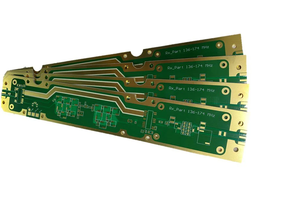
RO3003 is used in high-frequency applications such as RF antennas, automotive radar, 5G base stations, and microwave circuits. Because of its low loss and stable dielectric properties, ro3003 pcb is ideal for systems operating in GHz ranges. It is commonly found in:
- automotive radar (24 GHz / 77 GHz)
- ADAS systems
- 5G base stations
- RF antennas
- Microwave filters and couplers
- Satellite communication systems
In these applications, the stability of the ro3003 substrate directly affects overall system reliability.
How Much Does RO3003 Cost?
The ro3003 price or rogers ro3003 price depends on several factors:
1. Thicker laminates (e.g., 30 mil, 60 mil) typically cost more due to higher raw material usage and processing complexity.
2. Rolled copper (RA) used for high-frequency applications is more expensive than standard electrodeposited copper, but it delivers better signal performance.
3. Prototype quantities usually carry higher unit costs, while volume production significantly reduces the rogers ro3003 price.
4. Multilayer RF boards, hybrid stack-ups, and tight impedance control requirements increase fabrication cost.
5. RF materials like rogers ro3003 are subject to global demand fluctuations, which can influence pricing and lead time.
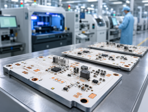
RO3003 PCB Manufacturing Services at EBest
At EBest Circuit (Best Technology), we provide end-to-end support for rogers ro3003 pcb projects, from early design validation to full-scale production. Our process is built around RF reliability, not just standard PCB fabrication.
What We Offer
- RF Stack-Up Optimization
We help define the correct ro3003 thickness, layer structure, and impedance targets before production begins.
- Impedance-Controlled Fabrication
Tight process control ensures the ro3003 dielectric constant is accurately reflected in real PCB performance.
- Hybrid Material Processing
Support for mixed structures such as RO3003 + FR4 or PTFE bonding systems for multilayer RF boards.
- Advanced Assembly Capability
High-precision SMT assembly for RF modules, including fine-pitch components and sensitive RF layouts.
- Full Inspection and Testing
AOI, X-ray inspection, and functional testing ensure each ro3003 pcb meets performance expectations.
Contact Us
Looking for a reliable supplier for RO3003 PCB, or need support with RF material selection?
EBest provides a one-stop solution from PCB fabrication to PCBA assembly.
Email: sales@bestpcbs.com
Email: sales@bestpcb.vn
You may also like
Tags: ro3003, ro3003 datasheet, ro3003 material, ro3003 thickness, rogers ro3003