PCB manufacturing PCB manufacturing
Home > Blog

ro4350b datasheet​

Rogers RO4350B PCB Laminate
Saturday, April 18th, 2026

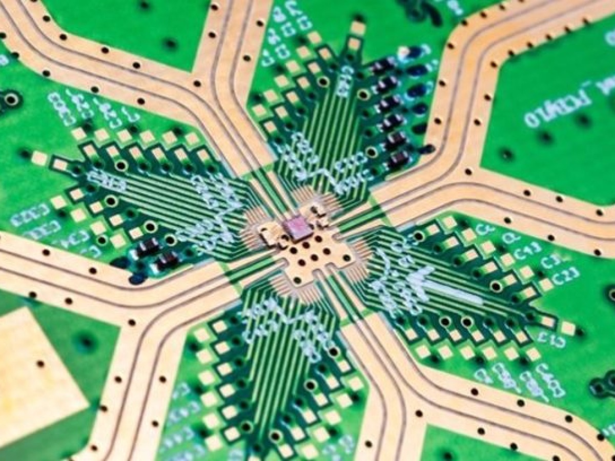
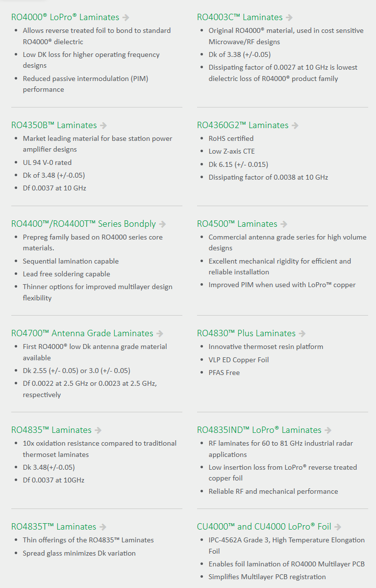
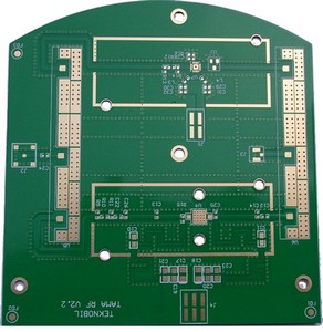
RO4350B PCB material is one of the most widely used laminates for high-frequency circuit design, especially in RF, microwave, and high-speed digital applications. As signal frequencies continue to increase in modern electronics—such as 5G communication, automotive radar, and satellite systems—the limitations of standard FR4 materials become more evident. Engineers increasingly require materials that can maintain low signal loss, stable dielectric performance, and reliable thermal behavior.

Rogers RO4350B PCB Laminate

What Is RO4350B PCB Material?

RO4350B PCB material is a hydrocarbon ceramic-filled laminate developed by Rogers Corporation, specifically engineered for high-frequency and RF circuit applications.

Unlike standard FR4 materials, RO4350B is designed to deliver:

  • Low dielectric loss for minimal signal attenuation
  • Stable dielectric constant (Dk) across wide frequency ranges
  • High thermal reliability under lead-free assembly
  • FR4-compatible processing, reducing manufacturing complexity

This combination allows engineers to design RF, microwave, and high-speed PCBs with predictable electrical performance while maintaining scalable production.

RO4350B Datasheet Overview

CategoryPropertyRO4350B Typical ValueEngineering Meaning
ThermalTg (DSC/TMA)>280 °CExcellent thermal stability, lead‑free safe
Td (5% weight loss)≥390 °CHigh thermal decomposition resistance
T260>30 minStrong resistance to delamination
T288>15 minWithstands high‑temp reflow
CTE (X/Y)10–12 ppm/°CMatches copper, minimal warpage
CTE (Z‑axis, <Tg)32 ppm/°CImproves PTH reliability
Thermal Conductivity0.69 W/m·KBetter heat dissipation than standard FR‑4
ElectricalDielectric Constant (10 GHz)3.48 ±0.05Design Dk = 3.66 for impedance
Dissipation Factor (10 GHz)0.0037Ultra‑low signal loss
Volume Resistivity1.2×10¹⁰ MΩ·cmHigh insulation stability
Surface Resistivity4.2×10⁹ MΩLow leakage risk
Dielectric Strength≥30 kV/mmGood insulation performance
MechanicalFlexural Strength≥250 MPaGood rigidity
Peel Strength≥1.0 N/mmReliable copper adhesion
Young’s Modulus~18 GPaStructural stability
Moisture & ReliabilityWater Absorption≤0.06%Stable in humid environments
CAF ResistanceVery GoodSafe for dense multilayer RF boards
FlammabilityUL 94 V‑0High safety standard
ProcessLead‑Free CompatibleYesStandard SMT assembly
Max Layer CountUp to 20–30 layersWorks for multilayer RF/HDI
Compatible PrepregRO4450BOptimized multilayer bonding

Key Features of RO4350B PCB Material

1. Excellent High‑Frequency Electrical Performance

Stable Dk 3.48 ±0.05 and ultra‑low Df minimize insertion loss and phase shift, supporting precise impedance control for antennas, filters, and high‑speed lines up to 77 GHz and beyond.

2. Outstanding Thermal Reliability

Tg >280 °C and high Td ensure stability during multiple lead‑free reflows. Low CTE in X/Y/Z axes reduces thermal stress, greatly improving via and board reliability under thermal cycling.

3. Easy Processing Like FR‑4

Unlike PTFE materials, RO4350B uses standard drilling, plating, and lamination. It supports mixed stackups with FR‑4, cutting cost while keeping RF performance.

4. Low Moisture & High Environmental Stability

Water absorption ≤0.06% maintains consistent electrical properties in high humidity. V‑0 rating and robust mechanical strength suit automotive, industrial, and aerospace environments.

5. Versatile Multilayer Compatibility

Paired with RO4450B prepreg for multilayer RF boards. Supports hybrid designs: RO4350B for RF layers, FR‑4 for digital/power layers to balance performance and BOM cost.

What Is the Dielectric Constant of RO4350B?

The RO4350B dielectric constant is:

  • 3.48 ± 0.05 at 10 GHz
  • ~3.66 for design calculations

This value remains stable from MHz to tens of GHz, which is critical for impedance-controlled RF designs.

Why This Matters

A stable Dk enables:

  • Accurate 50Ω transmission line design
  • Reliable RF matching networks
  • Consistent signal timing and phase control

In contrast, FR4 materials show significant variation with frequency, which leads to impedance drift.

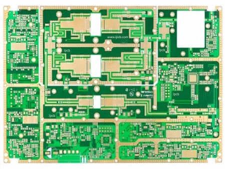
Applications of RO4350B PCB Material

  • 5G base stations, antennas, microwave filters
  • Automotive radar (24 GHz / 77 GHz ADAS)
  • RF power amplifiers, couplers, dividers
  • Satellite communications, aerospace radar
  • High‑speed backplanes and interconnects
  • WLAN, RFID, point‑to‑point radio
  • Test & measurement instrumentation

RO4350B vs RO4003C vs FR‑4

PropertyRO4350BRO4003CStandard FR‑4
Dk @10 GHz3.483.38~4.4
Df @10 GHz0.00370.00270.020–0.030
Tg>280 °C>280 °C130–150 °C
Thermal Conductivity0.690.64~0.25
FR‑4 Process CompatibilityYesYesN/A
Flame RetardantV‑0Non‑V‑0V‑0
Max FrequencyUp to 77 GHz+Up to 40 GHz~3 GHz
CostMediumMedium‑HighLow
Best ForGeneral RF, 5G, automotive radarUltra‑low‑loss RFLow‑speed digital

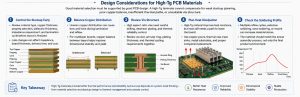
How to Choose RO4350B for Your PCB Design?

Choose RO4350B if:

  • Your design involves RF, microwave, or high‑speed signals >3 GHz
  • You need stable impedance and low insertion loss
  • You want FR‑4‑like processing but better performance
  • Applications: automotive radar, 5G, aerospace, test instruments
  • You need V‑0 flame retardant for commercial/industrial use

Consider alternatives if:

  • Extreme low loss → RO4003C
  • Pure cost priority → FR‑4 / S1000H
  • Non‑RF low‑speed digital → standard high‑Tg FR‑4

Frequently Asked Questions

1. What is the difference between RO4350B and FR-4?

While both can be processed using standard fabrication methods, they differ significantly in electrical performance. RO4350B is a hydrocarbon/ceramic laminate designed for high-frequency applications (up to 77 GHz), offering a stable dielectric constant (Dk) and much lower signal loss (Loss Tangent of 0.0037) compared to FR-4 (Loss Tangent of ~0.015–0.025). FR-4 typically struggles with signal integrity above 2–3 GHz, whereas RO4350B maintains its properties into the millimeter-wave range.

2. Is RO4350B compatible with standard lead-free soldering?

Yes. RO4350B has a high glass transition temperature (Tg > 280°C) and a decomposition temperature (Td) of 390°C. This makes it fully compatible with automated assembly and lead-free reflow soldering processes, which typically peak around 260°C. Its low Z-axis coefficient of thermal expansion (32 ppm/°C) also ensures that plated through-holes (PTH) remain reliable during thermal cycling.

3. What is the Dielectric Constant (Dk) of Rogers 4350B?

The standard design Dielectric Constant for RO4350B is 3.48 ± 0.05 at 10 GHz. This value is exceptionally stable across a wide frequency range, which is critical for designing controlled impedance transmission lines and wideband matching networks.

Note: For very thin materials (e.g., 0.004″), the Dk specification may shift slightly to 3.36.

4. How does RO4350B compare to RO4003C?

Both belong to the Rogers 4000 series, but the primary difference is the flame retardancy rating. RO4350B is UL 94 V-0 rated, making it the industry standard for commercial and active devices where fire safety certification is required. RO4003C is not UL 94 V-0 rated, though it offers a slightly lower loss tangent (0.0027) and a slightly lower Dk (3.38), making it preferable for specific passive applications where every fraction of a decibel counts.

5. Does RO4350B require special plasma etching for through-hole plating?

No. Unlike PTFE-based materials (like the Rogers 5000 or 6000 series), RO4350B is a thermoset hydrocarbon laminate. This means it can be processed using standard epoxy/glass (FR-4) techniques. It does not require specialized via preparation, such as sodium naphthenate or plasma etching, which significantly reduces manufacturing costs and lead times.

Get RO4350B PCB Support

If your project involves RF or high-speed PCB design, selecting the right material is critical.

We’re happy to support you with:

  • Stack-up design
  • RF PCB optimization
  • Fast PCB & PCBA production

📧 sales@bestpcbs.com

Feel free to reach out — your project will be supported by engineers who understand real RF challenges.

You may also like

Rogers RO4350B Datasheet & Material Guide for RF PCB Designers
Friday, December 5th, 2025

If you are working on RF or microwave PCB design, the material you choose directly impacts signal loss, phase stability, thermal performance, and overall system reliability. Rogers RO4350B is one of the most widely used high-frequency laminates in telecom, radar, 5G, satellite, and advanced wireless systems. This guide provides a complete breakdown of RO4350B datasheet properties, thickness options, RF advantages, and a comparison against FR4—plus practical manufacturing notes for PCB engineers.

What Is Rogers RO4350B Material?

Rogers RO4350B is a hydrocarbon-ceramic, glass-reinforced laminate engineered for RF and microwave applications from the Rogers RO4000® series. Unlike PTFE-based laminates, RO4350B can be fabricated using standard FR4 PCB processes—a huge benefit for cost, lead time, and manufacturability—while still delivering excellent electrical stability at GHz frequencies.

Key characteristics:

  • Dk = 3.48 ± 0.05 (10 GHz, z-axis)
  • Df ≈ 0.0037 (low loss)
  • High thermal stability
  • Low moisture absorption (<0.06%)
  • Compatible with FR4 processes
  • Excellent for hybrid stack-ups
Rogers RO4350B Datasheet & Material Guide for RF PCB Designers

What Is Rogers RO4350B Material?

What Is RO4350B Used for in RF PCB Applications?

RO4350B is found in nearly every modern RF system. Typical uses include:

  • 5G antennas and base-stations
  • Phased-array radar modules
  • LNA, PA, and front-end RF chains
  • Power amplifiers requiring robust thermal paths
  • Filters, couplers, baluns, and RF matching networks
  • Automotive ADAS radar
  • Satellite communication modules
  • High-performance mixed-signal and RF/digital hybrid boards

Because it balances cost and performance, RO4350B is ideal for mid-to-high volume RF production.

Rogers RO4350B Datasheet: Full Material Properties Overview

Below is a consolidated summary of all essential RO4350B datasheet values RF engineers frequently use in simulation, stack-ups, and manufacturing notes.

RO4350B Electrical Properties

PropertyTypical ValueTest Condition / Notes
Dielectric Constant (Dk)3.48Measured at 10 GHz
Dielectric Constant Stability±0.05Across thickness range
Dk Temperature Coefficient+50 ppm/°C−50°C to +150°C
Dissipation Factor (Df)0.0037@ 10 GHz
Volume Resistivity1×10⁷ MΩ·cmASTM D257
Surface Resistivity1×10⁷ MΩASTM D257
Dielectric Strength40 kV/mmTypical
Electrical Loss StabilityExcellentWideband RF use

RO4350B Thermal Properties

PropertyTypical ValueNotes
Thermal Conductivity0.69 W/m·KSupports heat-spreading features
Tg (Glass Transition Temperature)>280°CVery stable for lead-free
Td (Decomposition Temperature)≈390°CRogers method
CTE (X-axis)11 ppm/°CStrong dimensional stability
CTE (Y-axis)14 ppm/°CGood panel reliability
CTE (Z-axis)32 ppm/°CSupports plated through-hole reliability
T260 Time>60 minAnti-delamination performance
T288 Time>20 minHigh thermal endurance

RO4350B Copper Options

Copper TypeThicknessNotes
Rolled Copper½ oz, 1 ozBetter for low-loss RF lines
Electrolytic Copper½ oz, 1 oz, 2 ozStandard PCB production
Reverse-Treated CopperAvailableImproved adhesion in hybrid stack-ups

For more details about Rogers RO4350B, click here: Rogers RO4350B Datasheet Download

RO4350B Thermal Conductivity

RO4350B’s thermal conductivity of 0.69 W/m·K is significantly higher than typical FR4 (~0.3 W/m·K).

This means:

  • Better heat spreading
  • Higher reliability under RF power loads
  • Improved board life during thermal cycles
  • Lower risk of delamination

This makes RO4350B a strong candidate for RF power amplifiers and modules with high current density.

RO4350B Thickness Options & Common Stack-Up Selections

RO4350B thickness availability is wide, giving designers flexibility.

Common RO4350B Thicknesses

  • 0.101 mm / 0.004”
  • 0.203 mm / 0.008”
  • 0.254 mm / 0.010”
  • 0.3048 mm / 0.012”
  • 0.406 mm / 0.016”
  • 0.508 mm / 0.020”
  • 0.813 mm / 0.032”
  • 1.524 mm / 0.060”

Copper options: ½ oz, 1 oz, 2 oz.

Common Stack-up Approaches

1. RF-only board:

Single RO4350B core for antennas, filters, or couplers.

2. Hybrid stack-up (RO4350B + FR4):

  • RF layers on RO4350B
  • Digital/Power layers on FR4
  • Best cost-performance balance

3. Multilayer RO4350B stack-up:

For radar, high-power, or mmWave systems requiring uniform RF behavior.

RO4350B vs FR-4: Differences in RF Performance

FR-4 is a good general-purpose material but struggles at higher RF bands. Its dielectric constant shifts with humidity, temperature, and frequency. Loss levels rise significantly above 1–2 GHz, which affects range, efficiency, and signal clarity.

RO4350B addresses these issues with stable electrical behavior, low loss, and stronger control of impedance.

FeatureRO4350BFR-4
Dk StabilityVery stableUnstable at high frequency
Loss (Df)LowHigh
High-frequency useExcellentLimited
Thermal stabilityStrongModerate
RF performanceConsistentVaries widely
Typical useRF, microwave, antennasGeneral electronics

For RF paths, RO4350B is nearly always the better choice.

Rogers 4000 Series Materials Overview

The RO4000® series includes hydrocarbon-ceramic laminates designed for RF and microwave work. The series offers stable dielectric values, low moisture absorption, and predictable performance across frequency ranges. These materials support antennas, filters, couplers, radar units, medical sensors, and industrial communication systems. RO4003C and RO4350B are the most common choices, though other variants exist for special electrical or mechanical needs. Here are some other RO4000® series materials:

Rogers 4000 Series Materials Overview

Which Rogers Materials Can Be Used for RF & Microwave PCB?

Common Rogers RF materials include:

  • RO4350B – balanced performance, processable like FR4
  • RO4003C – lower loss, great for 10+ GHz
  • RO4835 – improved oxidation resistance and stability
  • RT/duroid® series – PTFE-based ultra-low-loss materials for mmWave
  • TMM® series – ceramic thermoset laminates for precision high-power RF

Choose based on frequency, thermal load, and tolerance requirements.

RO4350B PCB Manufacturing Considerations

Although RO4350B is easier to manufacture than PTFE materials, achieving consistent RF performance requires following specific process guidelines. Here are the key considerations for PCB fabrication:

RO4350B PCB Manufacturing Considerations

RO4350B PCB Manufacturing Considerations

1. FR4-compatible processing, but with controlled parameters

RO4350B supports standard PCB processes, but drill speeds, lamination pressure, bake profiles, and final copper thickness must be carefully controlled to ensure stable impedance and dielectric consistency.

2. Hybrid stack-ups require expert lamination control

When combining RO4350B with FR4, differences in CTE (coefficient of thermal expansion) must be managed to avoid warpage, resin starvation, or delamination. Precise prepreg selection and lamination cycles are essential.

3. Accurate impedance control is critical

RF designs often require ±5% or tighter impedance tolerance. Manufacturers must account for:

  • dielectric thickness tolerance
  • copper roughness
  • resin-filled vias or back-drilling
  • line-width compensation

Providing simulation models or stack-up notes (Dk/Df @ frequency) helps ensure fabrication accuracy.

4. Drilling & plating demands tighter control

RO4350B’s ceramic-filled structure requires optimized drill parameters to prevent smear and maintain high hole-wall quality, ensuring reliable via plating for multilayer RF PCBs.

5. Proper material storage and handling

To prevent moisture absorption and dimensional shift, the material should be kept in a dry, controlled environment and baked before lamination when necessary.

With these practices, RO4350B PCBs can achieve repeatable RF performance from prototype to mass production.

Why EBest Circuit (Best Technology) Is Preferred for RO4350B PCB Fabrication?

When working with RO4350B, choosing the right PCB manufacturer is critical. EBest Circuit (Best Technology) is trusted by RF engineers because:

  • They stock RO4350B in multiple thicknesses
  • Provide RF stack-up simulation support
  • Offer tight impedance control with test coupons
  • Perform high-precision routing and controlled-depth milling
  • Support hybrid RO4350B + FR4 multilayers
  • Provide material certifications and Rogers-lot traceability

If you need consistent RF performance from prototype to mass production, EBest Circuit (Best Technology) is a reliable partner for RO4350B PCB fabrication.

FAQs

1. Does RO4350B support buried or blind vias in multilayer RF boards?

Yes. RO4350B works well in multilayer designs that use blind or buried vias. Its mechanical strength and low z-axis expansion help maintain via reliability during lamination and thermal cycling. When designers use selective RO4350B layers inside a hybrid stack-up, careful lamination scheduling helps control movement and keep impedance stable.

2. Is RO4350B compatible with ENIG, immersion silver, or HASL finishes?

Yes. RO4350B supports common surface finishes, including ENIG, immersion silver, OSP, and certain types of lead-free HASL. Most RF boards use ENIG or immersion silver because these finishes give cleaner surfaces, consistent thickness, and smoother trace edges. A smooth finish helps reduce signal loss at high frequencies. HASL may be less preferred for controlled-impedance lines due to its uneven surface.

3. Can RO4350B be used for power amplifiers that generate heavy heat?

Yes. Many PA modules run on RO4350B because it handles heat better than FR-4 and holds impedance during thermal loads. Designers still need good thermal paths, such as thermal vias under power devices or metal backers for heat spreading. If the PA generates extreme heat, ceramic or metal-backed constructions may be considered. For most communication-grade PAs, RO4350B provides more than enough stability.

4. What stack-up mistakes should designers avoid when using RO4350B?

A common mistake is mixing RO4350B and FR-4 without modeling the transition area. The shift in dielectric constant affects line impedance if the transition is not controlled. Another mistake is routing sensitive RF lines too close to ground via fences, which can create unintended coupling. Over-constraining solder masks around RF traces may also shift the effective dielectric environment.

5. Is RO4350B more expensive than FR-4, and how does it impact project cost?

Yes, RO4350B costs more than FR-4 due to its electrical stability and engineered formulation. The material price is higher, and multilayer stacks may need tighter controls. However, the overall project cost can still drop because fewer design spins occur, RF tuning time is reduced, and system performance becomes more predictable. In many RF designs, the ROI justifies the material cost.

You may also like