





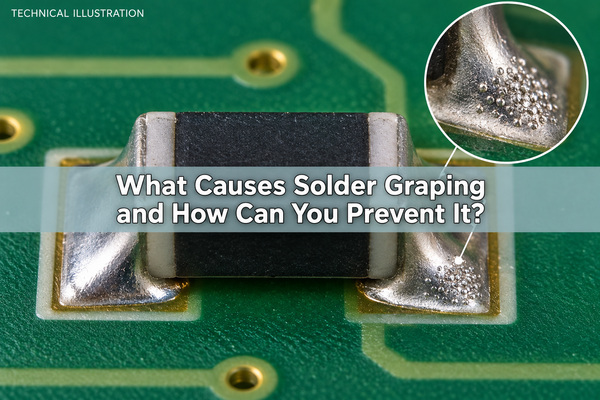
Solder graping is incomplete coalescence of solder powder, leaving a cluster of recognizable particles on a reflowed solder deposit. Small SMT paste deposits are especially vulnerable when exposed particles oxidize before the remaining flux can clean and protect them. The practical response is to check deposit volume and the measured reflow profile together, rather than immediately adding heat.
What Does Solder Graping Look Like?
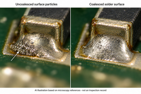
A graping solder defect usually appears as multiple rounded particles on the surface or edge of an otherwise coalesced solder deposit. Under magnification, the individual particle outlines remain visible instead of merging into the surrounding metal. Solder joint graping can be localized to the smallest pads while larger joints on the same assembly look normal.
A dull surface alone is not enough to identify graping. Lead-free joints can have a matte finish without containing uncoalesced powder. Record the component reference, affected termination and particle location; use consistent lighting and magnification when comparing boards. A photograph of a rough joint does not establish its root cause or electrical reliability.
Why Are Small Solder Paste Deposits More Vulnerable?
Small deposits expose a relatively large surface compared with the amount of paste available. During heating, flux can spread away from the upper particles. Those exposed particles then have less local protection against oxidation. This is why solder paste graping often concentrates around miniature components and small apertures rather than appearing uniformly across a board.
Two different geometries matter: the size of the whole printed deposit and the size of the powder particles inside it. A small deposit does not necessarily contain a finer powder grade, and changing powder grade does not correct an inconsistent print. Keep these variables separate when investigating the problem.
How Do Oxidation and Flux Depletion Cause Graping?
Solder paste oxidation obstructs the joining of adjacent particles. Flux removes existing oxides and helps protect surfaces during heating, but its useful activity and coverage are finite. Prolonged thermal exposure, unsuitable paste chemistry or flux spreading can leave exposed powder insufficiently protected before coalescence occurs.
Melting and coalescence are not identical. A particle can reach the alloy's melting range yet remain separated by an oxide skin. Consequently, a peak temperature reading above liquidus does not prove that every surface particle joined the deposit. Conversely, visible graping does not prove that the whole joint stayed below liquidus.
Paste history belongs in the investigation: check the manufacturer's storage, thawing, handling and stencil-life requirements against the actual batch record. Do not add solvent or liquid flux to solder paste as an improvised correction. That changes the formulation and print behavior without establishing a qualified process.
Does Finer Solder Powder Increase Graping Risk?
For an equal volume of spherical metal, smaller particles have more total surface area. In the idealized geometry, surface area divided by metal volume is 6/d, where d is particle diameter. Halving d doubles that ratio. This explains the increased oxidation burden associated with finer powder; it is not a prediction that the defect rate will double.
Finer powder may still be necessary for small stencil apertures. Select the paste by its printing requirements and demonstrated reflow performance, not by choosing the coarsest or finest grade automatically. If a coarser grade is evaluated, verify release, deposit consistency and the smallest features before treating it as an improvement. A more oxidation-resistant formulation must also satisfy residue, cleaning and electrical requirements for the assembly.
How Do Stencil Apertures and Paste Volume Affect Graping?
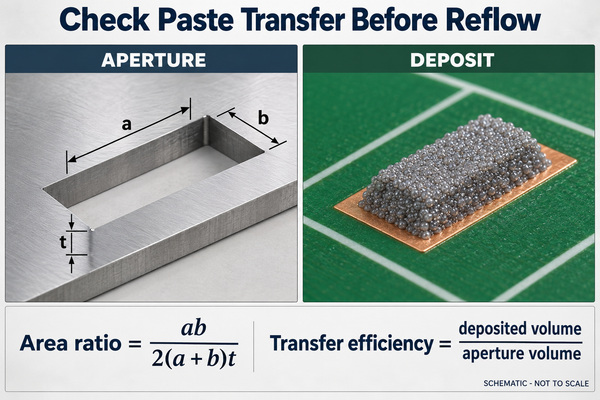
The stencil opening specifies a theoretical volume, but the board receives only the paste that releases from it. Incomplete or variable transfer can leave vulnerable small deposits. For a rectangular opening with length a, width b and foil thickness t, the area ratio is ab/[2(a+b)t]. It compares opening area with aperture wall area; it is not a solder-graping acceptance ratio.
Consider an illustrative 0.20 × 0.25 mm aperture in a 0.10 mm foil. Its area ratio is 0.556 and its theoretical volume is 0.005 mm³. If the measured deposit is 0.004 mm³, transfer efficiency is 80%. Those numbers describe this example only: neither 0.556 nor 80% is a universal pass/fail threshold. Repeatability and the released process limits still matter.
Our SMT stencils support the printing step where aperture geometry and paste release are established. On mixed-size assemblies, step-up and step-down stencils allow local foil-thickness changes, subject to spacing and printability review. Neither a thicker foil nor a larger aperture is an automatic cure: excess paste can create bridging or beading while a smaller area ratio can make release harder.
How Should You Adjust the Reflow Profile to Reduce Graping?
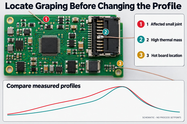
First measure the board, not just the oven settings. Place thermocouples at the affected small joint and representative high-thermal-mass and hot locations. Compare ramp, preheat or soak exposure, time above liquidus and peak against the selected paste's process window and the assembly's temperature limits.
If small deposits spend unnecessary time at elevated temperature before reflow, a shorter preheat or soak may preserve flux activity. However, shortening the profile must not leave heavy joints underheated. If the measured cold location fails the required process window, correct that deficiency rather than assuming every granular-looking joint has the same oxidation history.
Avoid changing peak, conveyor speed, paste and stencil at the same time. A better-looking board would then provide little evidence about which change helped. Check wetting, bridging, tombstoning and temperature-sensitive parts alongside the graping result; a profile that reduces one defect but creates another is not ready for production.
Can Nitrogen Reflow Prevent Solder Graping?
Nitrogen can reduce oxidation during reflow and widen the usable process window. It does not replenish depleted flux, repair poor paste transfer or prove that every joint has received sufficient heat. Evaluate atmosphere with the same paste, deposit geometry and measured thermal conditions wherever practical.
Better wetting can also change solder distribution and the balance of forces at small chip components. Compare other defects as well as graping. Use the residual-oxygen conditions specified and qualified for the process; there is no single nitrogen setting that can be inferred from the word “graping.”
How Is Graping Different from Solder Balls, Cold Joints and Slump?
Location and formation history help separate these problems. The distinctions below guide investigation, not automatic acceptance of a delivered assembly.
| Condition | What distinguishes it | What to check first |
|---|---|---|
| Graping | Recognizable powder particles remain at the solder deposit surface after reflow | Particle location, paste transfer, flux protection and the joint's actual profile |
| Solder balling or beading | Separate balls or beads occur outside the intended joint, sometimes beside or beneath a chip | Printing, paste displacement, placement and whether particles can move or bridge conductors |
| Cold solder joint | An inadequately formed joint, potentially involving insufficient heat or poor wetting; surface dullness alone is inconclusive | Joint formation, wetting and measured thermal history |
| Solder paste powder size | A material specification before printing, not itself a defect | Paste grade, aperture requirements and formulation compatibility |
| Slump | Paste spreads or loses its printed shape before full reflow | Cold/hot slump behavior, print-to-reflow delay and spacing |
These conditions can coexist. Hot spreading can expose powder and contribute to graping, while displaced paste can form a separate bead. Classifying everything as “solder balls” obscures those different corrective actions. A board that passes a basic continuity check still requires assessment of loose conductive particles and the applicable workmanship requirements.
How Can You Confirm the Cause of Solder Graping?
Use a controlled comparison rather than judging one improved photograph. Define the affected component population and the inspection method before starting. The following order preserves evidence from the print stage through reflow:
- Keep a baseline. Record paste product, alloy, lot, handling time, stencil revision, printer setup and oven program. Photograph representative affected and unaffected joints.
- Check deposition. Compare SPI volume, area and height at the problem pads with their released limits. Examine variation across board positions and consecutive prints, not only the average.
- Measure the thermal history. Confirm the small-joint and heavy-joint profiles on the populated assembly. Record atmosphere conditions where nitrogen is used.
- Change one practical factor. Test a justified profile change, transfer improvement or qualified paste alternative against the baseline. Keep the other conditions recorded and controlled.
- Inspect the trade-offs. Count affected joints using the same denominator and examine wetting, bridging, beading and tombstoning. Retain the unsuccessful trial results as well as the improved sample.
- Repeat before release. Confirm that the improvement survives the planned production conditions and inspection requirements. One passing board is not evidence of a stable process.
For example, “12 affected terminations out of 400 inspected” is more useful than “graping is lower.” The example is a reporting format, not our production result. Include which termination types were counted so a change in the product mix does not masquerade as an improvement.
What Can We Check for Your SMT Assembly?
At EBest Circuit (Best Technology), our PCB assembly service includes solder-paste printing, 3D SPI, placement, reflow and inspection. Our equipment includes a SINIC-TEK S8080 3D SPI system, a Suneast SER710NH nitrogen-capable reflow oven and a SINIC-TEK A510DL 3D AOI system. SPI examines the deposit before reflow; AOI examines visible assembly features afterward. Neither independently establishes the chemical cause of uncoalesced particles.
For a graping concern on a planned build, send us the PCB files, BOM, affected component references and available inspection images. Existing paste, stencil and profiling information helps us assess the relevant printing and assembly conditions. We can discuss the build and inspection scope before quoting; process changes and acceptance criteria should be agreed for the specific assembly rather than inferred from a generic defect name.
Solder Graping FAQs
Can you remove graping by cleaning the board?
Cleaning residue does not make separated solder particles coalesce. Loose particles and suspect joints need a defined disposition and, where required, an approved rework process. Do not brush a cluster into surrounding circuitry or assume that a cleaner-looking surface demonstrates a sound joint.
Is there an IPC limit called a solder graping ratio?
Do not confuse stencil area ratio with an acceptance limit for graping. Use the applicable workmanship document, revision, class and customer requirements to assess the actual condition, including particle attachment, joint formation and electrical clearance.
Can a second oven pass fix graping?
A second pass with already depleted flux can add thermal exposure without correcting coalescence. Evaluate the cause and an approved rework method first, including component and board thermal limits. Repeated reflow is not a substitute for correcting the original print or thermal process.
Reducing solder graping means preserving flux effectiveness while achieving adequate joint heating and repeatable paste deposition. For SMT build review, contact us at sales@bestpcbs.com with the assembly files and affected joint details.
You may also like



Tags: Reflow Soldering, SMT assembly, Solder Graping, Solder paste