Have you ever stared at a circuit board and wondered how to accurately recognize the tiny parts that power every electronic device? Circuit board electronic components are the building blocks of all modern electronics, and knowing how to identify them correctly is critical for troubleshooting, maintenance, and accurate analysis. This guide breaks down every essential step, from distinguishing different component types to reading markings, testing functionality, and protecting these parts, all with practical, actionable advice to solve common pain points and avoid costly mistakes.
What Are the Electronic Components of a Circuit Board?
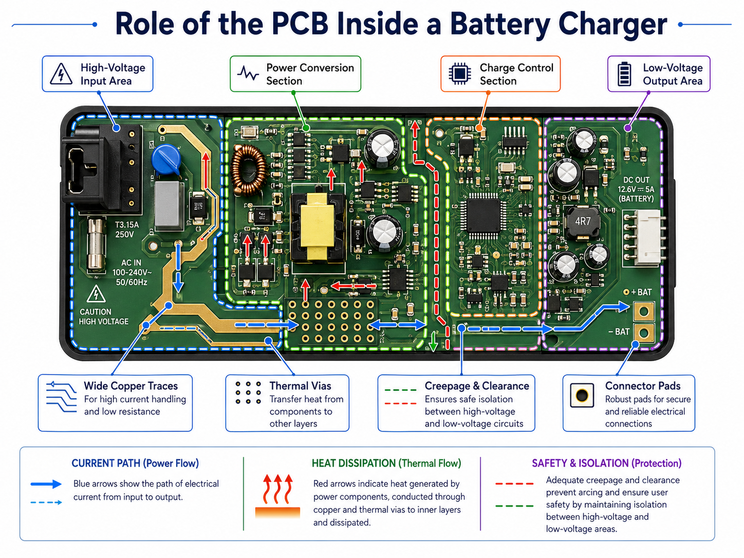
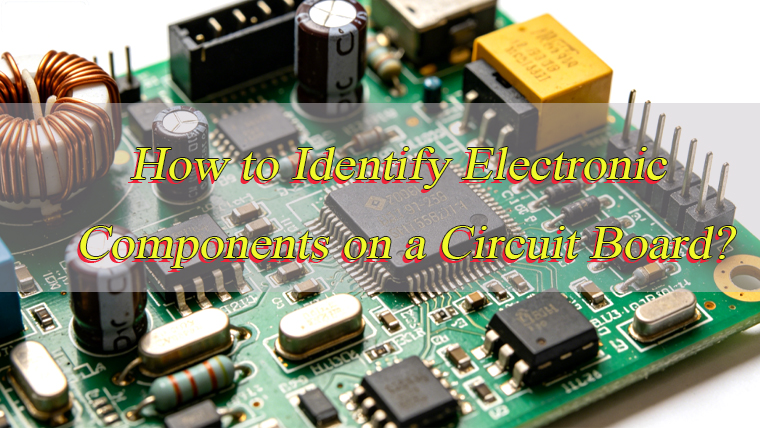
Electronic circuit board components are discrete parts that work together to enable the circuit’s functionality, each serving a specific electrical purpose. These components fall into two main categories: passive and active, with additional specialized types that support overall performance.
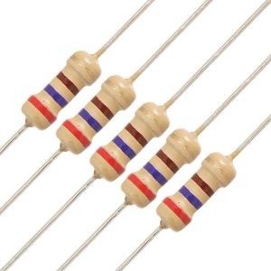
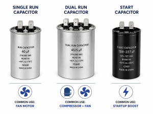
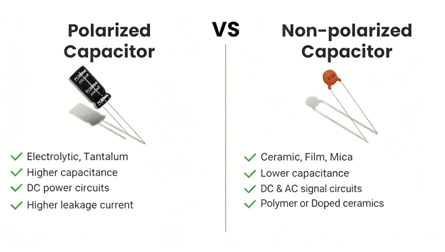
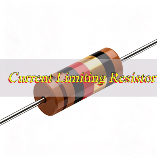
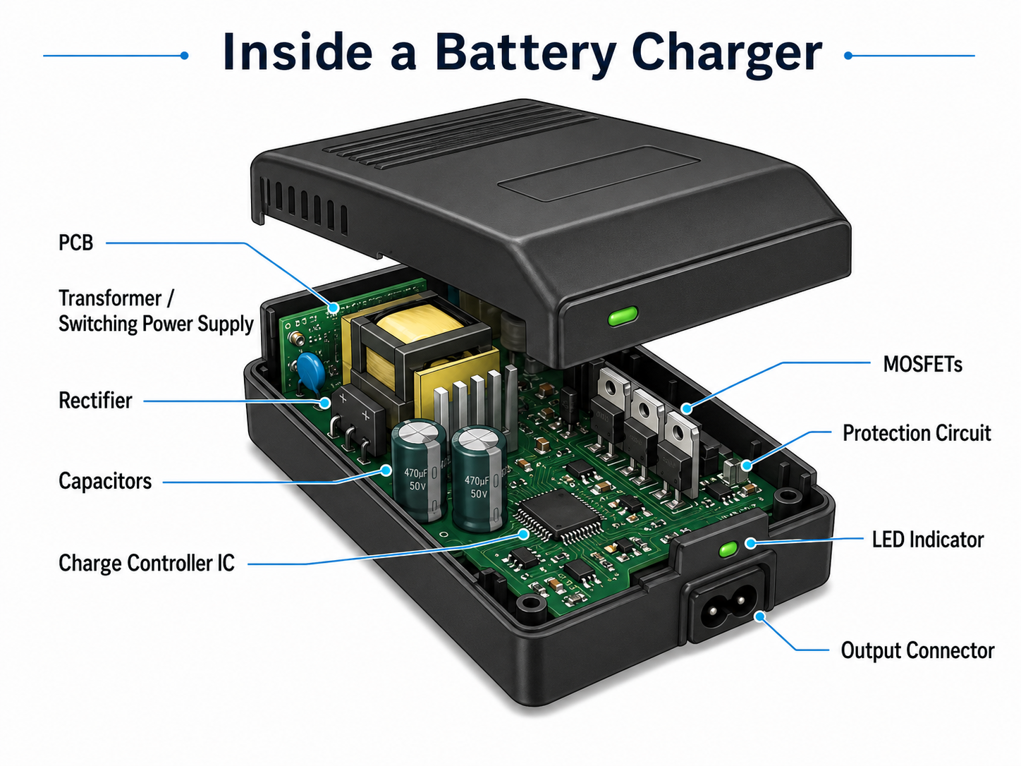
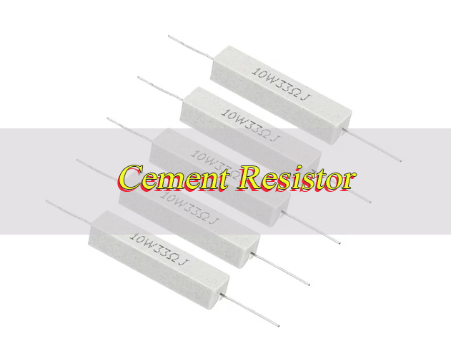
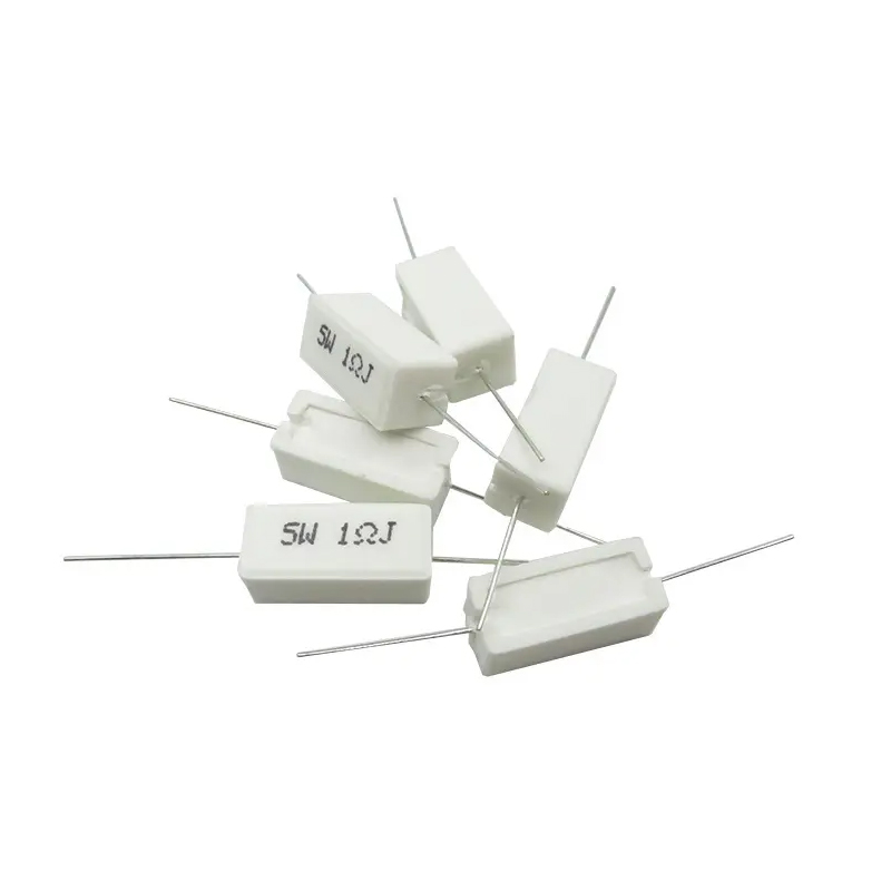
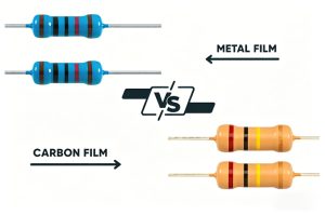
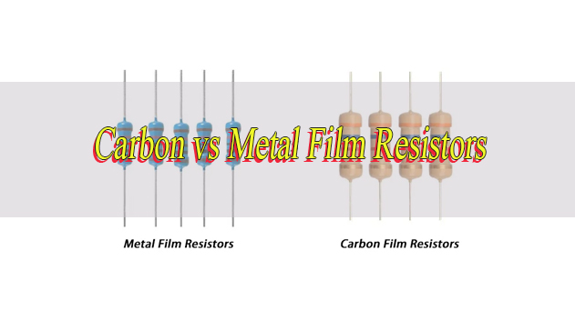
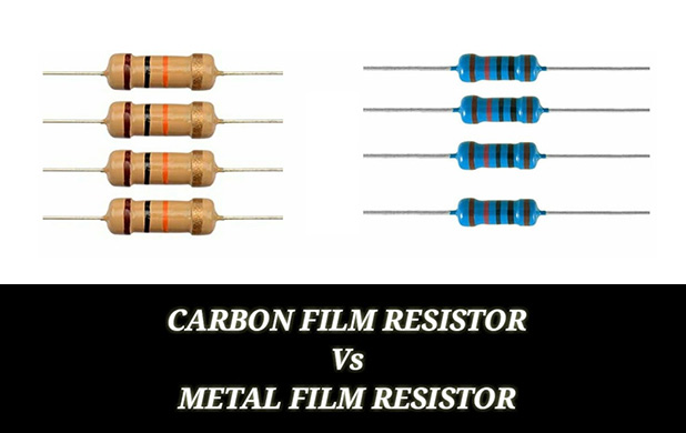
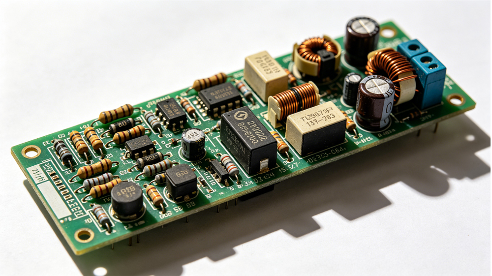
Passive components do not require external power to operate and are essential for regulating electrical signals. The most common passive components include resistors, which limit current flow and divide voltage; capacitors, which store and release electrical charge to filter noise and stabilize power; inductors, which store energy in magnetic fields and suppress voltage spikes; and diodes, which allow current to flow in only one direction. These components are found on every circuit board and form the foundation of basic circuit operation.
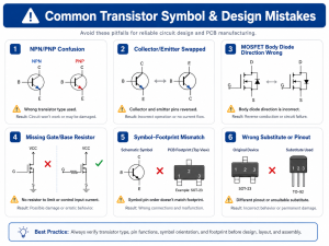
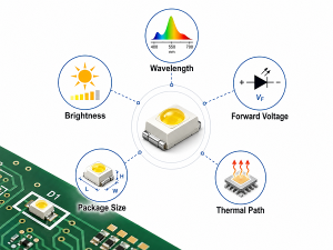
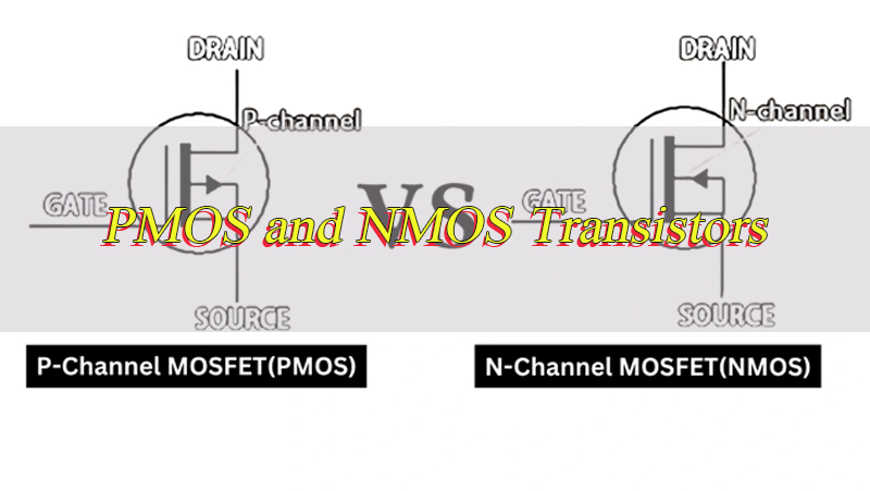
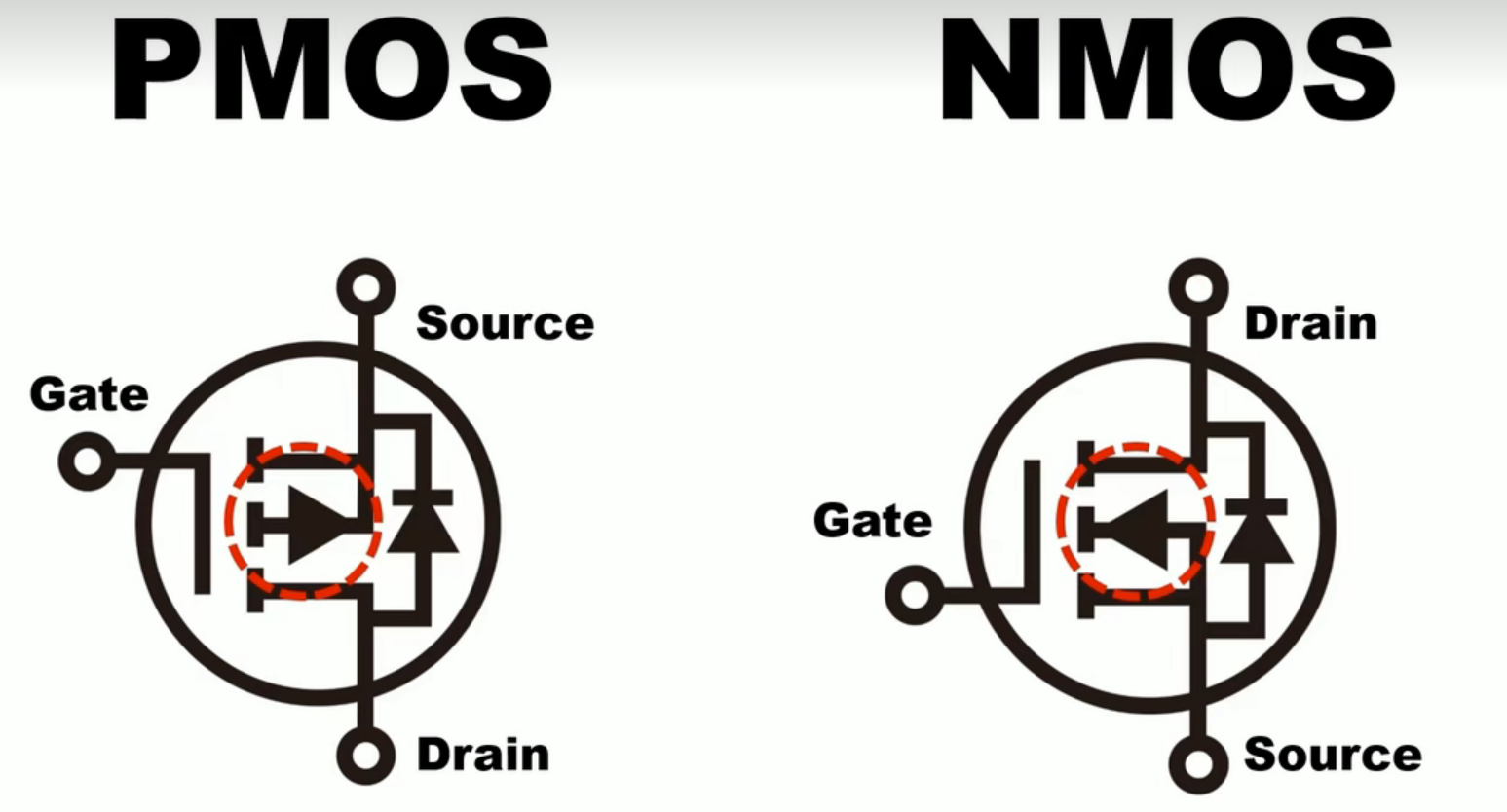
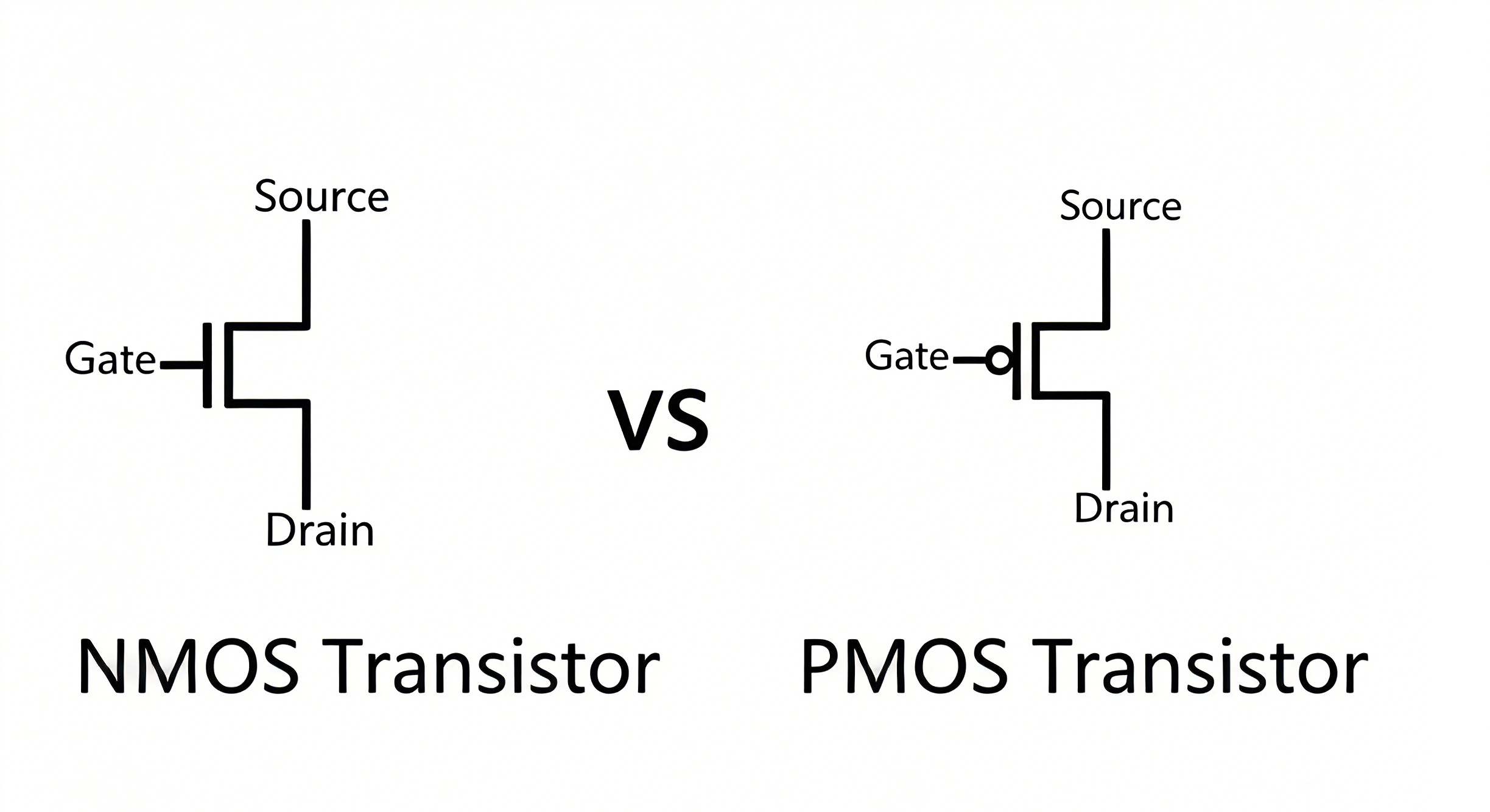
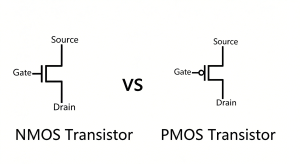
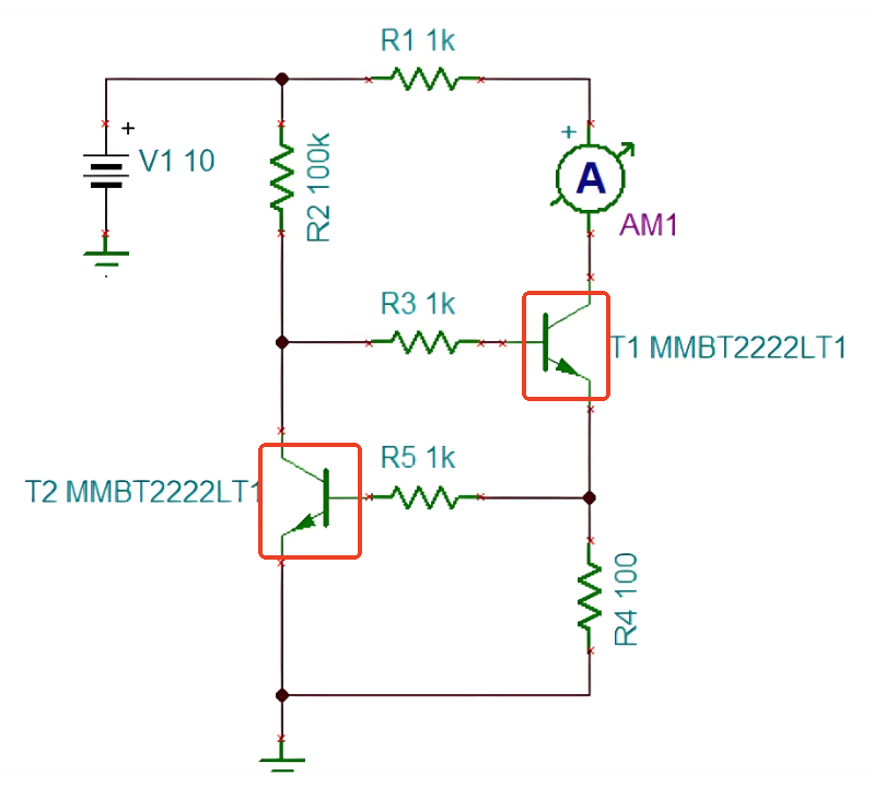
Active components require external power to function and can amplify signals or switch current. Transistors are key active components, used to amplify electrical signals and act as switches in digital circuits. Integrated circuits (ICs) are complex active components that pack hundreds or thousands of miniaturized components into a single chip, serving as the “brain” of the circuit for processing, control, or memory storage. Other active components include LEDs, which emit light when current passes through them, and relays, which switch high-power circuits using low-power signals.
Additional specialized components include fuses, which protect the circuit from overcurrent by melting and breaking the circuit; connectors, which link the circuit board to external devices or other boards; and switches, which control the flow of current by opening or closing the circuit. Together, these components form a cohesive system that enables the circuit board to perform its intended function, making circuit board electronic components indispensable to all electronic devices.
How to Distinguish Surface Mount and Through-Hole Circuit Board Electronic Components?
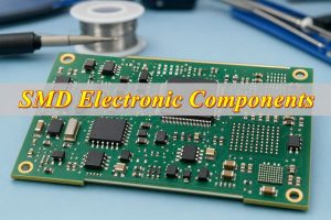
Distinguishing surface mount and through-hole circuit board electronic components is straightforward once you know their key physical and mounting characteristics. Both types serve the same electrical purposes but differ in design, mounting method, and application, with clear visual cues to tell them apart.
- Mounting Method: Surface mount components (SMDs) are soldered directly to the surface of the circuit board, with small terminals or pads that attach to copper traces on the board’s top or bottom. Through-hole components have long metal leads that pass through holes drilled in the circuit board, with soldering done on the opposite side of the board to secure the component.
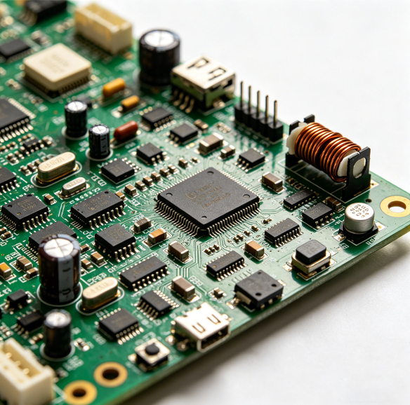
- Size and Shape: Surface mount components are significantly smaller and flatter than through-hole components. They come in compact rectangular, square, or chip-like shapes, with no protruding leads (or very short leads). Through-hole components are larger, with cylindrical or rectangular bodies and long, thin leads that extend outward from the component.
- Lead Configuration: Surface mount components have leads or pads along their edges or bottom, designed to sit flush against the circuit board. Through-hole components have one or more leads that extend straight out from the component body, intended to be inserted through pre-drilled holes in the board.
- Visual Cues: Surface mount components often appear as tiny “chips” on the board’s surface, with no leads visible through the board. Through-hole components have leads that pass through the board, with solder joints visible on the opposite side. Older circuit boards typically use more through-hole components, while modern, compact devices rely primarily on surface mount components.
- Application Context: Surface mount components are used in compact devices like smartphones, laptops, and wearables, where space is limited. Through-hole components are used in applications requiring high mechanical strength, such as industrial equipment, power supplies, and prototyping, where manual assembly and durability are prioritized.
How to Identify Electronic Components on a Circuit Board?
Identifying electronic components on a circuit board involves a combination of visual inspection, reading silk screen markings, and understanding component characteristics. Follow these step-by-step methods to accurately identify any component, even on dense or complex boards.
- Check Silk Screen Markings: Most circuit boards have a silk screen layer white or gray printed text and symbols that labels each component. These labels use standard abbreviations to indicate the component type: R for resistor, C for capacitor, D for diode, Q for transistor, U for integrated circuit, L for inductor, F for fuse, and SW for switch. The label (e.g., R12, C5, U3) corresponds to the component’s position in the circuit schematic, making identification quick and accurate.
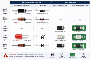
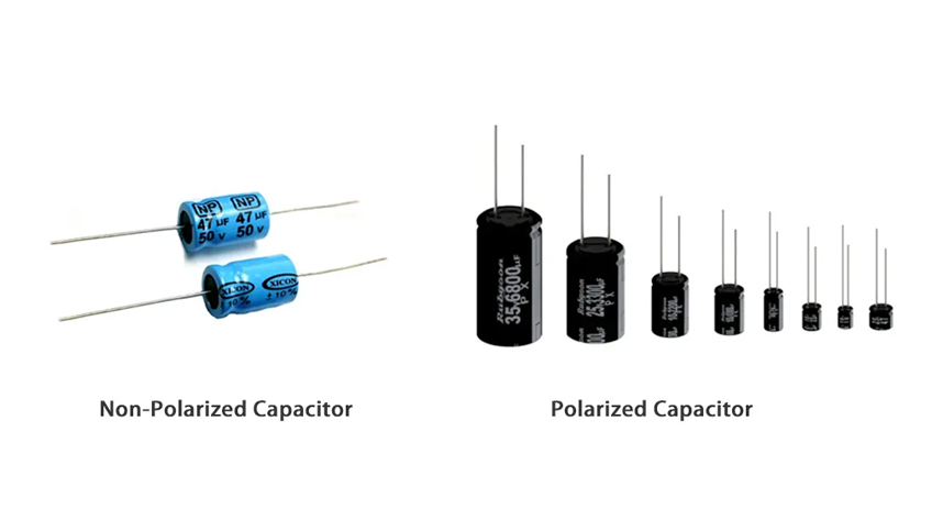
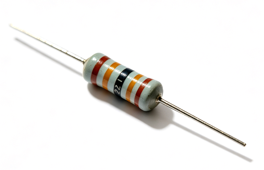
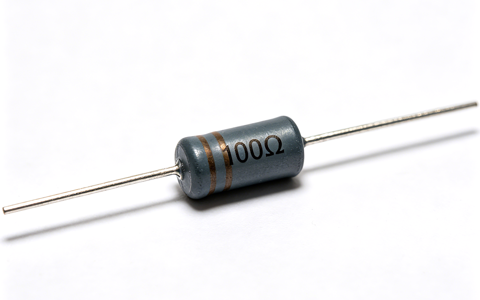
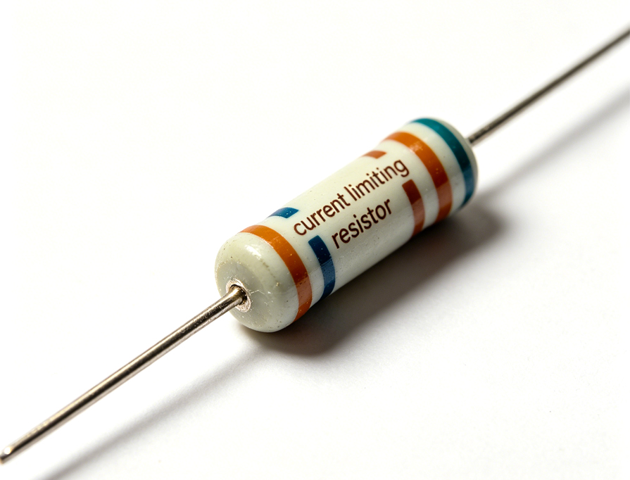
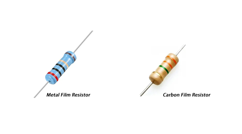
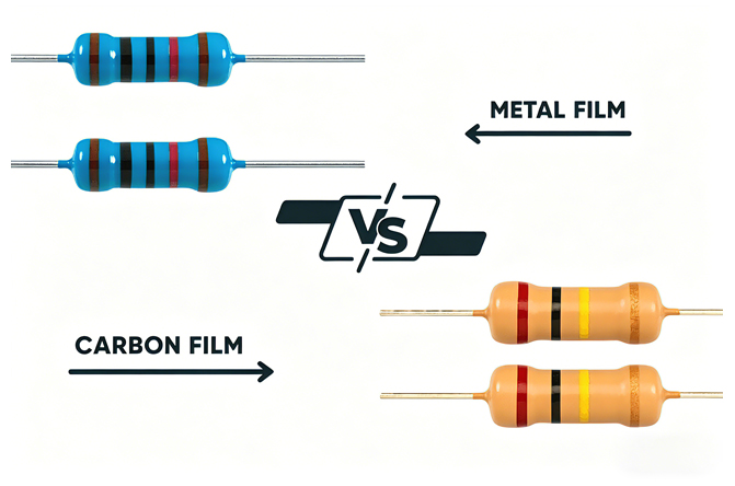
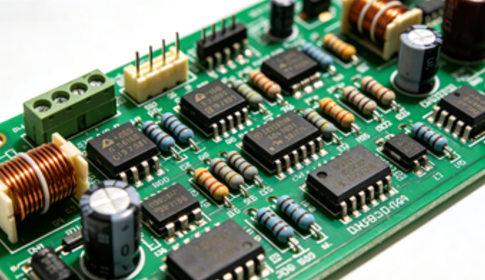
- Recognize Physical Characteristics: Each component type has distinct physical features. Resistors are small, cylindrical (through-hole) or rectangular (surface mount) with color bands or numerical codes. Capacitors are round (electrolytic), flat (ceramic), or rectangular (film) and may have voltage or capacitance markings. Diodes have a stripe on one end indicating the cathode (negative terminal). Integrated circuits are black chips with multiple legs or pads, often with a small dot or notch marking pin 1.
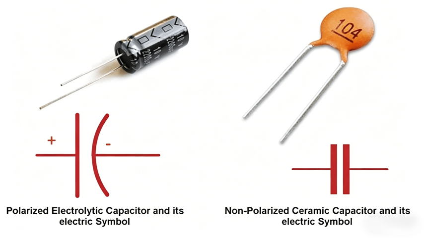
- Use Component Markings: Most components have printed markings that indicate their values, ratings, or part numbers. Resistors use color bands or 3-4 digit codes to show resistance and tolerance. Capacitors use numerical codes (e.g., 104 = 100,000 picofarads) or direct markings for capacitance and voltage. Transistors and ICs have part numbers that can be looked up to confirm their type and specifications.
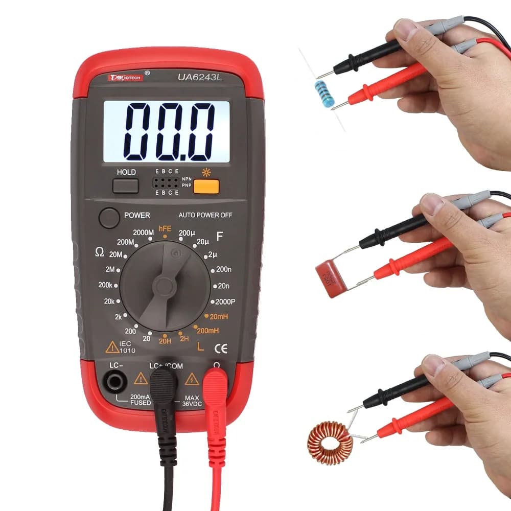
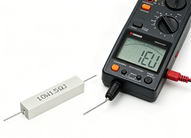
- Verify with a Multimeter: For uncertain components, use a multimeter to test electrical properties. Resistors can be tested for resistance, capacitors for capacitance, diodes for forward/reverse bias, and transistors for continuity between pins. This step confirms the component’s type and functionality, ensuring accurate identification.
- Cross-Reference with Schematics: If available, use the circuit board’s schematic diagram or bill of materials (BOM) to cross-reference component labels. Schematics show the component’s role in the circuit, while the BOM lists exact part numbers and specifications, eliminating guesswork.
How to Read the Markings and Codes on Circuit Board Electronic Components?
Markings and codes on circuit board electronic components provide critical information about their specifications, including value, tolerance, voltage rating, and functionality. Reading these codes correctly is essential for identifying components and ensuring they meet the circuit’s requirements, with standardized formats for each component type.
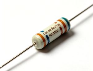
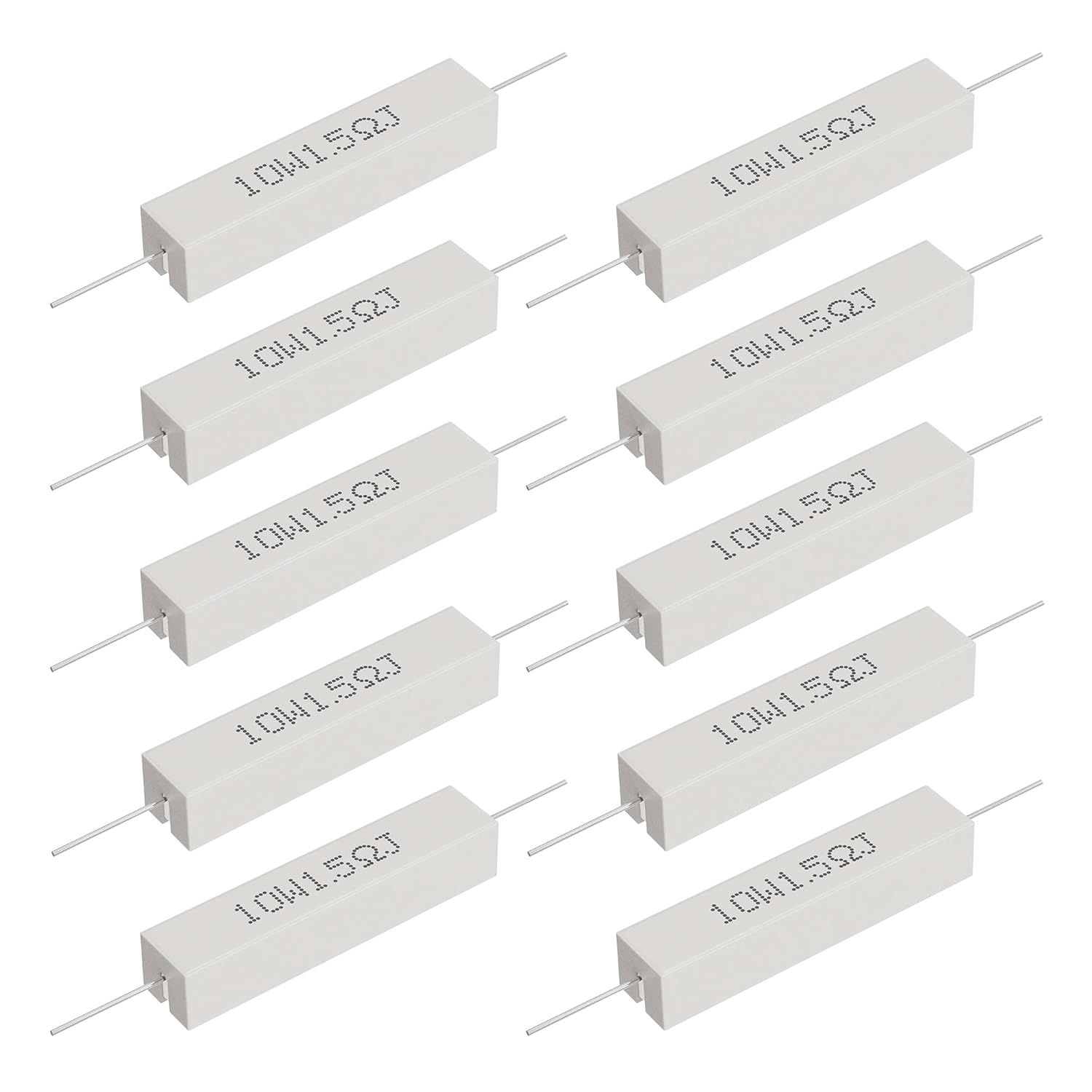
- Resistor Markings: Through-hole resistors use color bands to indicate resistance and tolerance. The first two bands are the significant digits, the third band is the multiplier, and the fourth band (if present) is the tolerance. Surface mount resistors use 3 or 4-digit codes: 3-digit codes have two significant digits and one multiplier (e.g., 102 = 10 x 10² = 1,000 ohms), while 4-digit codes have three significant digits and one multiplier (e.g., 1002 = 100 x 10² = 10,000 ohms). Tolerance is often marked with a letter: J = ±5%, K = ±10%, M = ±20%.
- Capacitor Markings: Capacitor markings vary by type and size. Large electrolytic capacitors directly print capacitance (e.g., 10µF) and voltage (e.g., 25V) on the body. Small surface mount capacitors use 2 or 3-digit codes: the first two digits are significant, the third is the multiplier (in picofarads), with no decimal point (e.g., 104 = 10 x 10⁴ = 100,000 pF = 100 nF). Some capacitors use letters to indicate tolerance, with J = ±5% and K = ±10% being common.
- Diode Markings: Diodes have a single stripe on one end, which marks the cathode (negative terminal). Some diodes also have part numbers printed on the body (e.g., 1N4001), which can be looked up to confirm their type (e.g., rectifier diode) and voltage/current ratings. LEDs have a similar stripe for the cathode, with additional color markings to indicate the light color.
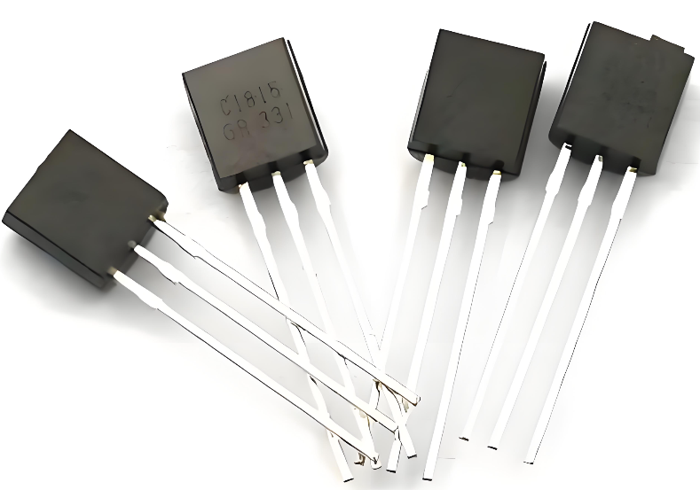
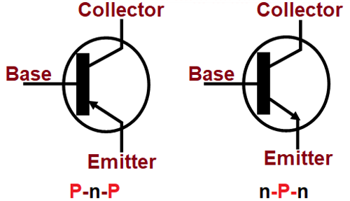
- Transistor Markings: Transistors have alphanumeric part numbers (e.g., 2N2222, BC547) printed on the body. These part numbers identify the transistor type (NPN, PNP) and specifications like current, voltage, and gain. Some transistors also have a dot or notch to indicate the collector, base, or emitter pin.
- Integrated Circuit (IC) Markings: ICs have a part number (e.g., ATmega328P, LM358) printed on the top, which identifies the chip’s functionality (e.g., microcontroller, operational amplifier). A small dot or notch on the IC marks pin 1, which is critical for proper orientation when installing or testing the component. Some ICs also include manufacturer logos or date codes.
What Tools Are Needed to Identify Electronic Circuit Board Components Accurately?
Accurate identification of electronic circuit board components requires a few essential tools, designed to enhance visibility, measure electrical properties, and verify component functionality. These tools are affordable, easy to use, and critical for avoiding misidentification and costly errors.
- Magnifying Glass or Digital Microscope: Most circuit board electronic components are tiny, with small markings that are difficult to read with the naked eye. A magnifying glass (1020x magnification) works for basic inspection, while a digital microscope provides higher magnification and allows for detailed viewing of small surface mount components and fine markings.
- Digital Multimeter: A multimeter is the most versatile tool for component identification. It measures resistance (for resistors), capacitance (for capacitors), voltage (for diodes and ICs), and continuity (for testing component leads). Look for a multimeter with auto-ranging functionality for ease of use, as it automatically selects the correct measurement range.
- Component Tester: A dedicated component tester quickly identifies resistors, capacitors, diodes, transistors, and inductors by measuring their key parameters and displaying the component type and value. This tool eliminates guesswork, especially for unmarked surface mount components.
- Gerber Viewer Software: Gerber files are used to design circuit boards, and Gerber viewer software allows users to visualize the board’s layers, component footprints, and silk screen markings. This tool helps cross-reference component labels with their physical positions on the board, useful for complex or dense circuits.
- Soldering Iron and Desoldering Tool: For components that need to be removed for closer inspection or testing, a soldering iron (2530W for surface mount, 4060W for through-hole) and desoldering tool (solder sucker or desoldering braid) are essential. These tools allow safe removal of components without damaging the circuit board or the component itself.
- Flashlight or Task Light: Proper lighting is critical for visual inspection. A bright, focused flashlight or task light illuminates small components and markings, making it easier to read silk screen labels and component codes, especially on dark or densely populated circuit boards.
How to Identify Faulty Circuit Board Electronic Components During Identification?
Identifying faulty circuit board electronic components during inspection involves recognizing visual signs of damage and using tools to test functionality. Faulty components often show clear physical indicators, and simple tests can confirm whether a component is working correctly, saving time in troubleshooting.
- Visual Inspection for Physical Damage: Look for obvious signs of damage, such as burnt or discolored components (common in resistors and ICs), bulging or leaking capacitors (electrolytic capacitors often bulge when faulty), cracked component bodies, or broken leads. These visual cues indicate a faulty component that needs replacement.
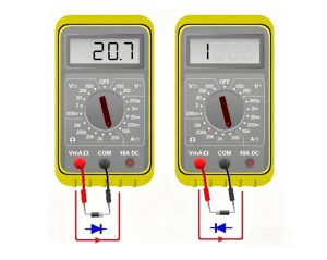
- Test for Continuity: Use a multimeter in continuity mode to check for broken leads or internal damage. A component with broken leads will show no continuity, while a faulty resistor or diode may show inconsistent continuity. For example, a diode should show continuity in one direction only; continuity in both directions indicates a faulty diode.
- Measure Component Values: Compare the measured value of a component to its marked value. A resistor with a measured resistance significantly higher or lower than its marked value is faulty. A capacitor with a measured capacitance below 80% of its marked value is likely faulty and should be replaced.
- Check for Overheating: During operation, touch components (carefully to avoid burns) to feel for excessive heat. Components that are abnormally hot (beyond their normal operating temperature) are likely faulty, as overheating indicates internal damage or incorrect operation.
- Inspect Solder Joints: Faulty solder joints (cold solder, bridging, or poor adhesion) can cause components to function incorrectly. Look for solder joints that are dull, cracked, or not fully covering the component lead and circuit board pad. These joints can be reflowed with a soldering iron to restore connectivity.
- Cross-Reference with Circuit Behavior: If the circuit is not functioning as intended, cross-reference the component’s role in the schematic with the observed behavior. For example, a non-functional LED may indicate a faulty resistor (limiting current) or a faulty LED itself. Testing the component’s value will confirm which is faulty.
How to Test Electronic Components on a Circuit Board?
Testing electronic components on a circuit board ensures they function correctly and meet the circuit’s specifications. The testing process varies by component type but follows a consistent, step-by-step approach using basic tools, with clear pass/fail criteria for each component.
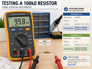
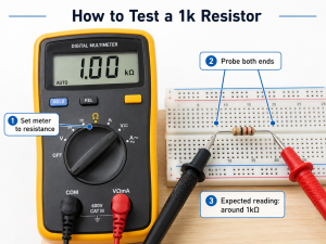
- Resistor Testing: Set the multimeter to resistance mode (ohms). Touch the multimeter probes to the resistor’s leads (no need to remove the resistor from the board if it is not in parallel with other components). Compare the measured resistance to the resistor’s marked value. A measured value within the component’s tolerance (±5%, ±10%, or ±20%) indicates a working resistor; a value outside this range means the resistor is faulty.
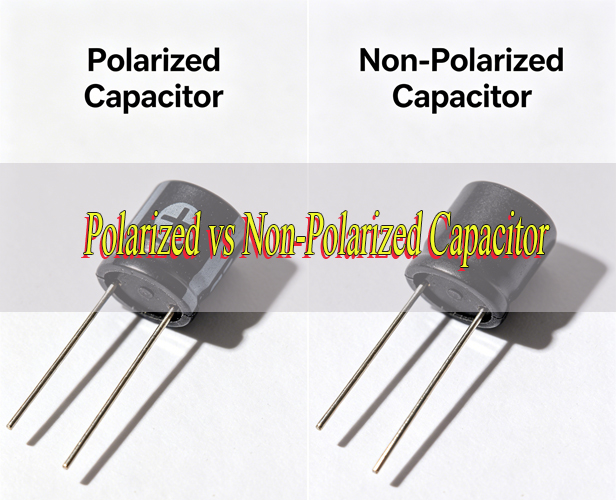
- Capacitor Testing: Set the multimeter to capacitance mode. For large electrolytic capacitors, discharge them first (use a resistor to discharge stored charge). Touch the probes to the capacitor’s terminals (match positive to positive, negative to negative for polarized capacitors). A measured capacitance within 10-20% of the marked value is acceptable; values significantly lower indicate a faulty capacitor.
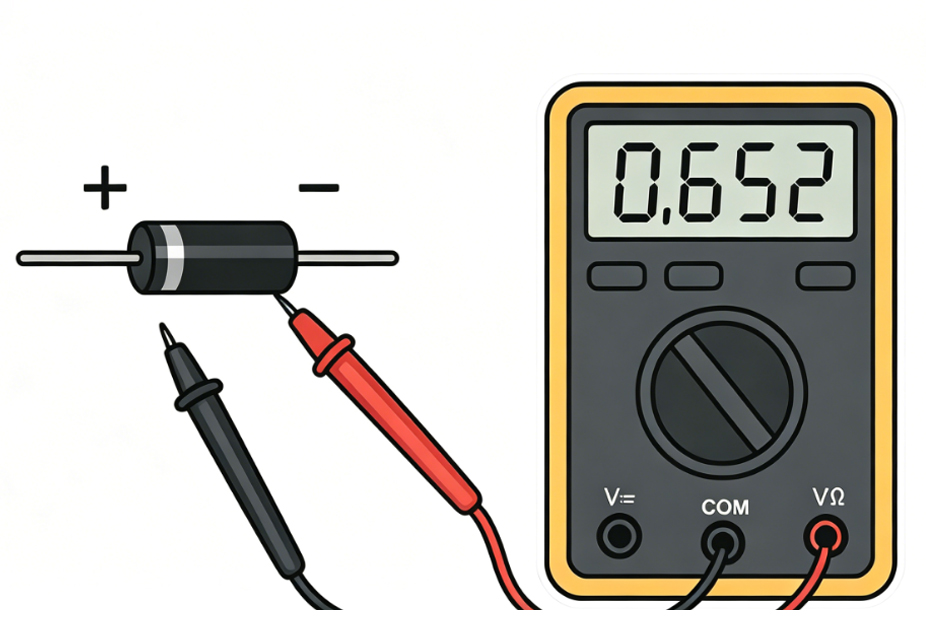
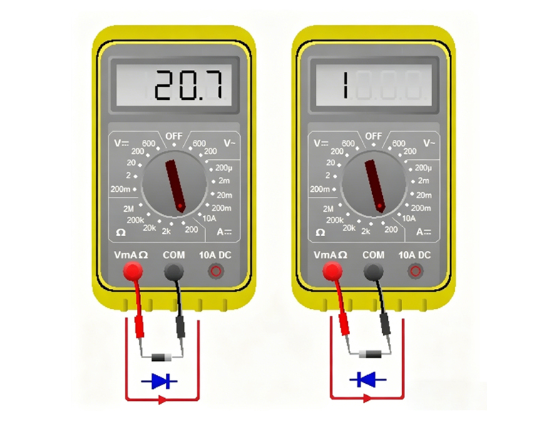
- Diode Testing: Set the multimeter to diode mode. Touch the positive probe to the diode’s anode (no stripe) and the negative probe to the cathode (stripe). A working diode will show a voltage drop (0.5-0.7V for silicon diodes). Reverse the probes, no voltage drop should be displayed. If voltage is displayed in both directions or no voltage is displayed in either direction, the diode is faulty.
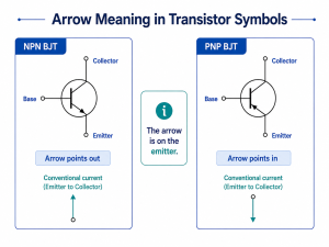
- Transistor Testing: For NPN transistors, set the multimeter to diode mode. Touch the positive probe to the base and the negative probe to the emitter, this should show a voltage drop. Touch the positive probe to the base and the negative probe to the collector, another voltage drop should be displayed. Reverse the probes for PNP transistors. No voltage drop in either test indicates a faulty transistor.
- Integrated Circuit (IC) Testing: Testing ICs requires a multimeter and knowledge of the chip’s pinout (from the datasheet). Measure the voltage at the power pins (VCC and GND) to ensure the IC is receiving power. Check the output pins against the expected voltage (from the schematic). If the IC is not receiving power or the output is incorrect, the IC is likely faulty. For more detailed testing, use an IC tester or oscilloscope.
- Inductor Testing: Set the multimeter to resistance mode. Touch the probes to the inductor’s leads. A working inductor will show low resistance (near zero ohms). High resistance or no continuity indicates a broken inductor coil, which is faulty.
How to Remove Electronic Components from a Circuit Board?
Removing electronic components from a circuit board requires care to avoid damaging the board, the component (if reuse is needed), and surrounding components. The process varies slightly for surface mount and through-hole components, but follows consistent best practices to ensure safe removal.
- Prepare the Workspace: Ensure the circuit board is disconnected from power and any external devices. Use an anti-static mat and anti-static wristband to prevent electrostatic discharge (ESD) damage to sensitive components. Gather the necessary tools: soldering iron, desoldering tool (solder sucker or desoldering braid), tweezers, and a magnifying glass.
- Removing Through-Hole Components: Heat the solder joint on one lead of the component with the soldering iron. Once the solder melts, use the desoldering sucker to remove the molten solder. Repeat for the other lead(s). Once all solder is removed, gently pull the component’s leads through the board using tweezers. If solder remains in the holes, use the desoldering braid to remove it.
- Removing Surface Mount Components: Use a soldering iron with a fine tip or a hot air station (preferred for small components). For components with multiple leads (e.g., ICs), heat all leads simultaneously with the hot air station (set to 300350°C) until the solder melts. For single-lead components (e.g., resistors, capacitors), heat one lead at a time, using tweezers to lift the component once the solder melts. Avoid applying excessive heat, as this can damage the circuit board’s copper traces.
- Clean the Solder Pads: After removing the component, use desoldering braid to clean any remaining solder from the circuit board’s pads. This ensures the pads are flat and free of debris, making it easier to install a new component if needed.
- Inspect for Damage: After removal, inspect the circuit board for damaged copper traces or pads. If a trace is lifted or damaged, use a soldering iron to reattach it (if possible) or use a jumper wire to restore connectivity. Inspect the removed component for damage if reuse is intended.
- Handle Components Carefully: Use tweezers to handle components, avoiding direct contact with the leads or pins. This prevents ESD damage and contamination from oils on the hands, which can affect component performance.
How to Avoid Damaging Circuit Board Electronic Components During Identification?
Damaging circuit board electronic components during identification is a common mistake that can lead to costly repairs or component failure. Following these simple steps ensures components and the circuit board remain intact during inspection, testing, and handling.
- Use Anti-Static Protection: Electrostatic discharge (ESD) can damage sensitive components like ICs and transistors. Always use an anti-static mat and anti-static wristband when handling the circuit board and components. Avoid touching component pins or leads directly with bare hands, as oils and static can cause damage.
- Avoid Excessive Heat: When using a soldering iron or hot air station, set the temperature to the minimum required (300350°C for surface mount components, 4060°C for through-hole). Excessive heat can melt component bodies, damage circuit board traces, or cause internal component failure. Limit heat exposure to 510 seconds per solder joint.
- Use the Right Tools: Avoid using sharp tools (e.g., screwdrivers, knives) to pry components, as this can damage leads, pins, or circuit board pads. Use tweezers with fine tips for handling small components, and a magnifying glass to avoid accidental contact with surrounding components.
- Do Not Force Components: If a component does not lift easily after desoldering, do not force it. Reheat the solder joints to ensure all solder is melted, and check for any hidden solder bridges that may be holding the component in place. Forcing components can break leads or lift copper traces.
- Discharge Capacitors Before Testing: Capacitors store electrical charge even after the circuit is disconnected from power. Discharge them using a resistor (1k10k ohms) before testing or removing them, as stored charge can cause electric shock or damage to the multimeter.
- Keep the Workspace Clean: A cluttered workspace increases the risk of dropping tools or components onto the circuit board, causing physical damage. Keep tools organized and the workspace free of debris, and use a soft mat to place the circuit board on to prevent scratches.
How to Protect Electronic Components on a Circuit Board?
Protecting electronic components on a circuit board ensures long-term reliability and prevents damage from environmental factors, ESD, and physical wear. Proper protection methods vary by application but focus on shielding components from harm while maintaining their functionality.
- Apply Conformal Coating: Conformal coating is a thin, protective layer applied to the circuit board and components to shield them from moisture, dust, chemicals, and temperature variations. Common coating materials include acrylic (easy to remove, good for general protection), silicone (excellent heat resistance), and polyurethane (high chemical resistance). The coating is applied evenly, covering all components without blocking connectors or heat sinks.
- Use Heat Sinks: Components that generate significant heat (e.g., ICs, power transistors) require heat sinks to dissipate heat and prevent overheating. Heat sinks are attached to the component’s body using thermal paste, which improves heat transfer. Choose a heat sink size appropriate for the component’s power dissipation to ensure effective cooling.
- Implement ESD Protection: Install ESD protection components (e.g., TVS diodes, varistors) on the circuit board to divert static charge away from sensitive components. Use anti-static packaging for components during storage and transportation, and ensure the circuit board is grounded during assembly and operation.
- Protect Against Overcurrent and Overvoltage: Use fuses or circuit breakers to protect components from overcurrent, which can cause overheating and damage. Install voltage regulators or Zener diodes to prevent overvoltage, which can destroy sensitive components like ICs and transistors. These components act as a safety net, breaking the circuit or regulating voltage when limits are exceeded.
- Secure Components with Potting Compound: For circuit boards used in harsh environments (e.g., industrial, automotive), potting compound is poured over the board and components to provide complete protection from moisture, vibration, and physical damage. Potting compound is a rigid or flexible material that encapsulates the board, forming a protective barrier.
- Proper Storage and Handling: Store circuit boards in a dry, cool environment, away from direct sunlight and moisture. Use anti-static bags for individual boards or components, and avoid stacking boards to prevent physical damage. When handling, use anti-static protection and avoid touching component pins or leads.
FAQs About Electronic Components on a Circuit Board
Q1: Can I identify circuit board electronic components without removing them from the board?
A1: Yes, most circuit board electronic components can be identified without removal. Use silk screen markings to determine component type, visual cues to recognize physical characteristics, and a multimeter to test electrical properties. For unmarked components, use a component tester or cross-reference with the circuit schematic to confirm identification.
Q2: Why do some surface mount components have no markings?
A2: Small surface mount components (e.g., 0402 or 0201 size resistors and capacitors) often have no markings due to their tiny size. Manufacturers mark the reels holding these components instead of individual parts. To identify unmarked surface mount components, use a component tester to measure their values or cross-reference with the circuit’s BOM or schematic.
Q3: How do I know if a capacitor on a circuit board is faulty?
A3: Faulty capacitors often show visual signs like bulging, leaking, or discoloration. To confirm, use a multimeter to measure capacitance. A capacitor with a measured value below 80% of its marked value is faulty. Additionally, capacitors that overheat during operation or cause circuit malfunctions (e.g., voltage fluctuations) are likely faulty and should be replaced.
Q4: What is the difference between passive and active electronic circuit board components?
A4: Passive components do not require external power to operate and include resistors, capacitors, inductors, and diodes. They regulate electrical signals but do not amplify or switch current. Active components require external power and include transistors, ICs, LEDs, and relays. They amplify signals, switch current, or perform complex processing tasks.
Q5: How can I avoid ESD damage when working with circuit board electronic components?
A5: To avoid ESD damage, use an anti-static mat and anti-static wristband to ground yourself and the circuit board. Avoid touching component pins or leads with bare hands, and store components in anti-static bags. Ensure the workspace is free of static-generating materials (e.g., plastic, fabric) and ground all tools used during inspection and testing.