

AC capacitor wiring is one of the most common topics people search for when an air conditioner fan stops spinning, the compressor hums, or a replacement capacitor needs to be installed. A capacitor looks simple from the outside, but its wiring must match the air conditioner’s electrical diagram, motor requirements, and terminal labels.
This guide explains how AC capacitor wiring works, what capacitor wire colors usually mean, how to read a basic AC capacitor wiring diagram, and how 3-wire and 4-wire dual capacitor connections are commonly arranged. It also covers common wiring mistakes and safety points customers should understand before working with HVAC systems or related PCBA control projects.
What Is AC Capacitor Wiring?
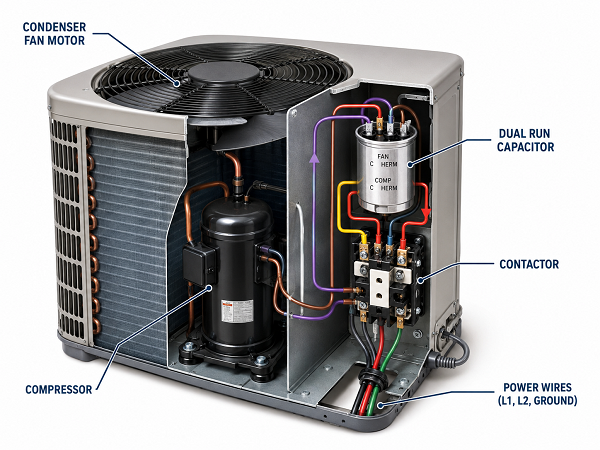
AC capacitor wiring refers to the electrical connections between an air conditioner capacitor, the compressor, the condenser fan motor, and the contactor or power circuit. In most residential and light commercial air conditioners, the capacitor supports motor operation by providing the phase shift needed for the motor to start and run correctly.
The capacitor does not work alone. It is part of a larger electrical system that includes motors, relays, contactors, fuses, wiring harnesses, and sometimes a control PCB or PCBA product. If one wire is placed on the wrong terminal, the fan or compressor may fail to start, run unevenly, or overheat.
Why Is the AC Capacitor Important in an Air Conditioner?
An air conditioner uses electric motors to run the compressor and the condenser fan. These motors need the correct electrical phase relationship to produce starting torque and stable rotation. The capacitor helps create that phase shift.
In a typical outdoor AC unit, the capacitor may support:
- The compressor motor
- The condenser fan motor
- Motor starting assistance
- Continuous motor running performance
A weak or failed capacitor often causes clear symptoms. The fan may need a push to start, the compressor may hum without running, or the system may shut down due to overheating or breaker trips. These symptoms are not always caused by the capacitor, but the capacitor is often one of the first parts technicians inspect.
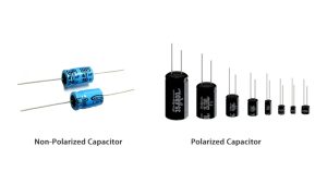
Main Types of AC Capacitors
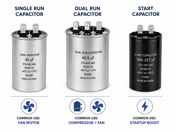
AC systems may use different capacitors depending on the motor design and equipment structure. The three common types are single run capacitors, dual run capacitors, and start capacitors.
| Capacitor Type | Main Function | Common Application | Key Selection Point |
|---|---|---|---|
| Single run capacitor | Supports one motor during operation | Fan motor or compressor motor | Match capacitance and voltage rating |
| Dual run capacitor | Supports compressor and fan motor in one can | Outdoor condenser unit | Correct C, FAN, and HERM wiring is critical |
| Start capacitor | Provides short starting boost | Hard-start circuits or certain compressor systems | Usually used with a relay or start device |
A dual run capacitor is common in air conditioners because it combines two capacitor sections inside one package. One side supports the compressor, and the other supports the fan motor. This saves space and reduces component count, but it also makes wiring accuracy more important.
How Do AC Capacitor Terminals Work?
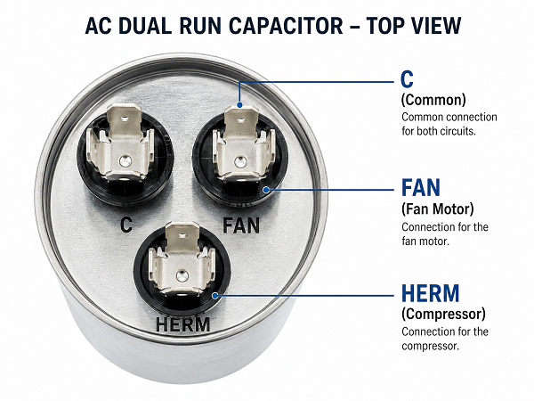
Most dual run capacitors have three terminal groups: C, FAN, and HERM. These labels are usually stamped or printed on the capacitor top. The number of metal spade tabs on each terminal group may vary, but the label is the key reference.
| Terminal Label | Meaning | Typical Connection |
|---|---|---|
| C | Common | Common side of the circuit, often linked to the contactor or incoming power path |
| FAN | Fan motor | Condenser fan motor capacitor wire |
| HERM | Hermetic compressor | Compressor capacitor wire |
The C terminal is the shared point for the capacitor. The FAN terminal connects to the condenser fan motor circuit. The HERM terminal connects to the compressor circuit.
AC Capacitor Wiring Colors: What Do They Mean?
AC capacitor wiring colors can help identify the original connection, but they are not universal. Different HVAC brands, motor manufacturers, repair histories, and field modifications can change the color pattern.
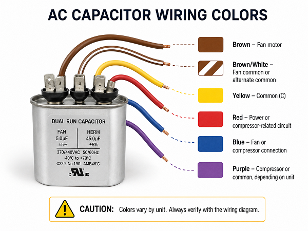
The table below shows common color usage, not a guaranteed rule.
| Wire Color | Common Meaning in Many AC Units | Important Note |
|---|---|---|
| Brown | Fan motor capacitor wire | Often goes to FAN on a dual capacitor |
| Brown/White | Fan motor common or capacitor common | May connect to C, depending on motor design |
| Yellow | Common or contactor-side connection | Often seen on C terminal |
| Red | Power, control, or compressor-related circuit | Must be traced with the wiring diagram |
| Blue | Fan or compressor-related connection | Usage varies by unit |
| Purple | Compressor-related circuit in some systems | Not universal |
The safest rule is simple: use wire color for tracing, but use the unit wiring diagram for confirmation. If the original capacitor is still installed, take a clear photo before removing any wire. Mark each wire by terminal label, not only by color.
AC Capacitor Wiring Diagram: How to Read It Correctly
An AC capacitor wiring diagram shows how the capacitor connects to the motor circuits and power path. It may be printed on the service panel, inside the outdoor unit cover, or in the equipment manual.
When reading the diagram, focus on these items first:
- Capacitor terminal labels: C, FAN, HERM
- Compressor terminals and wire path
- Fan motor wires
- Contactor connections
- Incoming power lines
- Any start relay, hard-start kit, or control board interface
Do not read the diagram as a physical picture of where wires sit on the capacitor. A wiring diagram shows electrical relationships, not always the exact physical layout.
3 Wire AC Dual Capacitor Wiring Diagram
A 3 wire AC dual capacitor wiring diagram is common in many air conditioner condenser units. In this arrangement, one wire connects to each major capacitor terminal group: C, FAN, and HERM.
A simplified 3-wire dual capacitor connection is shown below.
| Dual Capacitor Terminal | Typical Wire Destination |
|---|---|
| C | Common circuit or contactor side |
| FAN | Condenser fan motor |
| HERM | Compressor |
In a typical layout, the fan motor capacitor wire connects to FAN, the compressor wire connects to HERM, and the common wire connects to C. However, some systems may have additional wiring through contactors, control boards, or safety devices. The diagram on the equipment must take priority.
For replacement work, the technician should compare three things before moving wires:
- Old capacitor terminal labels
- New capacitor terminal labels
- Unit wiring diagram
If the new capacitor has a different shape or tab arrangement, the wiring should still follow the terminal labels, not the old physical position.
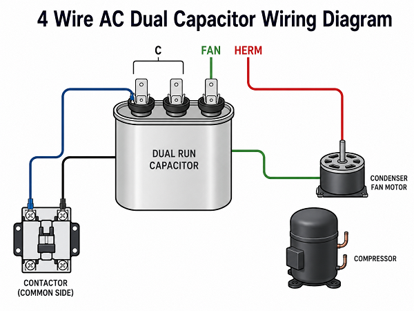
4 Wire AC Dual Capacitor Wiring Diagram
A 4 wire AC dual capacitor wiring diagram usually means one terminal group has more than one wire connected, most often the C terminal. This happens because the common terminal can serve more than one circuit path.
A simplified 4-wire dual capacitor arrangement may look like this:
| Dual Capacitor Terminal | Typical Wire Destination |
|---|---|
| C | Common wire to contactor or power circuit |
| C | Additional common wire, motor return, or control path |
| FAN | Condenser fan motor |
| HERM | Compressor |
The fourth wire does not create a new capacitor terminal function. It usually means one terminal group has multiple connections. On many dual capacitors, the C terminal has several spade tabs for this reason.
The main risk in a 4-wire setup is misidentifying the extra wire. If it is placed on FAN or HERM by mistake, the motor circuit may not operate correctly. Before replacement, label every wire according to the terminal it came from.
3 Wire vs 4 Wire AC Capacitor Wiring: What Is the Difference?
The main difference is not the capacitor function. Both systems can use the same C, FAN, and HERM terminal logic. The difference is the number of external wires connected to those terminals.
| Item | 3 Wire Dual Capacitor | 4 Wire Dual Capacitor |
|---|---|---|
| Number of connected wires | Usually one wire on C, FAN, and HERM | Usually two wires on one terminal, often C |
| Wiring complexity | Easier to trace | Requires closer wire identification |
| Common terminal use | Single common path | Multiple common or shared paths |
| Service risk | Moderate | Higher if the extra wire is not labeled |
| Best practice | Match labels and diagram | Label each wire before removal |
The practical takeaway is simple: a 4-wire capacitor connection is not automatically more advanced. It often just reflects how the equipment routes common connections.
Common AC Capacitor Wiring Mistakes
Most capacitor wiring problems come from rushed replacement, unclear photos, or overreliance on color. The capacitor may be correct, but one wrong connection can stop the system from running.
Common mistakes include:
- Connecting the fan wire to HERM
- Connecting the compressor wire to FAN
- Moving wires based on terminal position instead of label
- Assuming every brown wire always goes to the same place
- Replacing a dual run capacitor with the wrong capacitance rating
- Ignoring the voltage rating
- Forgetting to reconnect an extra common wire
- Installing a capacitor with loose or corroded terminals
- Failing to check the original wiring diagram
- Using poor-quality connectors that loosen under vibration
A loose terminal can cause heating, arcing, intermittent motor failure, or early capacitor damage. In production equipment, connector retention force and crimp quality should be part of the inspection standard, not an afterthought.
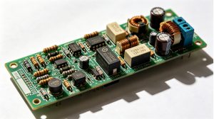
For PCB and PCBA assemblies used in HVAC control systems, EBest Circuit (Best Technology) supports engineering review for connector placement, copper thickness, solder joint reliability, and assembly process control. These details matter when a board must work near motors, relays, and high-current wiring.
What Happens If an AC Capacitor Is Wired Wrong?
If an AC capacitor is wired wrong, the result depends on which connection is incorrect. Some mistakes stop the motor immediately. Others allow the system to run briefly but damage the motor or capacitor over time.
| Wiring Problem | Possible Result |
|---|---|
| FAN and HERM reversed | Fan or compressor may fail to start correctly |
| Common wire missing | Motor circuit may remain open |
| Extra common wire misplaced | System may behave unpredictably |
| Wrong capacitance rating | Motor may overheat or run inefficiently |
| Loose terminal | Heat, arcing, or intermittent operation |
| Wrong capacitor type | Motor may not receive correct start or run support |
A miswired capacitor can cause a fan that does not start, a compressor that hums, repeated breaker trips, or premature motor failure. If the unit behaves abnormally after replacement, power should be turned off and the wiring should be checked before further operation.
How to Replace an AC Capacitor Safely?
AC capacitor replacement involves electrical shock risk. A capacitor can hold stored energy even after power is turned off. If you are not trained to work on HVAC electrical systems, the safe decision is to call a licensed HVAC technician.
A safety-focused replacement process includes the following checks:
- Turn off power at the breaker and outdoor disconnect.
- Confirm power is off with a proper meter.
- Take clear photos of the existing wiring before removing wires.
- Label each wire by capacitor terminal: C, FAN, or HERM.
- Confirm the replacement capacitor matches the required microfarad rating.
- Use an equal or higher voltage rating as allowed by the equipment specification.
- Discharge the capacitor using a proper discharge method or service tool.
- Move wires according to terminal labels, not physical position.
- Check that all terminals are tight.
- Restore power only after the wiring has been verified.
The capacitance rating is usually written in microfarads, such as 35/5 µF or 45/5 µF on a dual run capacitor. The larger value is usually for the compressor side, and the smaller value is usually for the fan side. The voltage rating may be 370VAC, 440VAC, or another specified value. A higher voltage rating may be acceptable in many cases, but the capacitance value must match the motor requirement.
For HVAC-related PCB or PCBA projects, reliable electrical design is not limited to the circuit board. Connector layout, wire harness documentation, copper design, assembly quality, and testing all affect long-term product stability. If you need PCB or PCBA support for air conditioning controls, motor interface boards, relay modules, or related electronic assemblies, send your files and requirements to EBest Circuit (Best Technology) at sales@bestpcbs.com.
FAQs About AC Capacitor Wiring
What color wire goes to C on an AC capacitor?
Yellow is often used for the C terminal, but this is not guaranteed. Some systems may use red, blue, or another color. Always follow the unit wiring diagram and the original terminal connection.
What color wire goes to FAN on an AC capacitor?
Brown is commonly used for the fan capacitor wire. Some fan motors also have a brown/white wire that may connect to common. Confirm with the fan motor label and AC wiring diagram.
What color wire goes to HERM on an AC capacitor?
The HERM terminal connects to the compressor circuit. The wire color varies by equipment brand and wiring design. Do not rely on color alone.
Can I replace a 3-wire capacitor with a 4-wire capacitor?
A capacitor is not selected by wire count alone. It must match the capacitance rating, voltage rating, capacitor type, and terminal function. A 4-wire connection usually means one terminal has multiple wires, often common.
Can I use a higher voltage AC capacitor?
In many HVAC applications, using a capacitor with a higher voltage rating is acceptable if the capacitance value and type match the equipment requirement. The replacement part should still follow the manufacturer’s specification.
What happens if C and FAN are reversed?
The fan motor may fail to start or run incorrectly. In some cases, the motor or capacitor may overheat. Turn off power and verify wiring before operating the unit again.
Is AC capacitor wiring the same for every air conditioner?
No. The C, FAN, and HERM logic is common on dual run capacitors, but wire colors, harness layout, and control circuits vary by model.
Should I follow wire colors or the wiring diagram?
Follow the wiring diagram. Wire colors are helpful for tracing, but the diagram and terminal labels are the correct references.
Why does my dual capacitor have several tabs on one terminal?
Multiple tabs allow more than one wire to connect to the same terminal group. This is common on the C terminal.
What information should I provide for a PCB or PCBA quotation related to HVAC equipment?
Provide Gerber files, schematic, BOM, board thickness, copper thickness, surface finish, connector type, relay or motor-load current, operating voltage, test requirements, quantity, and any safety or reliability requirements. For engineering support, contact EBest Circuit (Best Technology) at sales@bestpcbs.com.
You may also like


Tags: 3 wire ac dual capacitor wiring diagram, 4 wire ac dual capacitor wiring diagram, ac capacitor wiring, ac capacitor wiring colors, ac capacitor wiring diagram