Do you struggle to accurately test a diode and determine if it’s functioning properly, or wonder why your diode test results are inconsistent even when using a multimeter?
Testing a diode is a fundamental skill for anyone working with electronic circuits, as a faulty diode can cause signal distortion, energy loss, or complete circuit failure.
This guide breaks down every step of diode testing with a multimeter, addresses common pain points, and provides clear, actionable instructions to ensure reliable results every time.
Whether using a digital or analog multimeter, or even testing without a dedicated diode tester function, you’ll learn the exact techniques to verify diode performance, identify damage, and avoid costly mistakes.

What Tool is Used to Test a Diode?
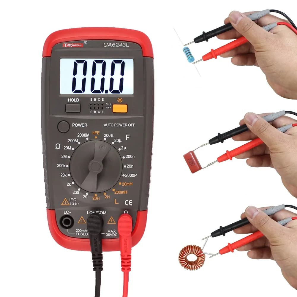
The primary tool for testing a diode is a multimeter, available in two main types. Both digital and analog multimeters can perform a diode test, though digital models often have a dedicated function for greater accuracy. Below are the two types of multimeters used for diode testing, along with their key features and typical use cases:
- Digital Multimeter: It comes with a dedicated diode test mode, a digital display for precise voltage and resistance readings, auto-ranging options, and a low battery indicator. It is the most common tool for diode testing, ideal for quick and accurate results with minimal interpretation.
- Analog Multimeter: It features a needle display, manual range selection, and uses an internal battery for resistance measurements. It does not have a dedicated diode mode and instead uses the resistance mode for testing. It is suitable for basic diode testing when a digital multimeter is unavailable, though it requires more interpretation of readings.
What is the Symbol for Diode Test on Multimeter?
The diode test symbol on a multimeter is standardized across most models, making it easy to identify once you know what to look for. The symbol varies slightly between digital and analog multimeters but follows the same core design.
- Digital Multimeter: The diode test symbol is typically a triangle pointing to a vertical line. This symbol directly represents the diode’s structure, where the triangle is the anode and the vertical line is the cathode. It is often labeled “DIODE” or “DI” next to the symbol for clarity. On some models, this symbol shares a position with the continuity test (represented by a sound wave icon), so you may need to press a function button to switch between continuity and diode test modes.
- Analog Multimeter: Analog models rarely have a dedicated diode test symbol because they use the resistance mode for diode testing. Instead, look for the resistance symbol (Ω) to select the appropriate range for testing. The resistance symbol is a horseshoe-shaped icon, and you will need to choose a low resistance range (typically R×10 or R×100) for accurate diode readings.
How to Prepare a Multimeter Before You Test a Diode?
Proper preparation of a multimeter is critical to ensure accurate diode test results and avoid damage to the multimeter or the diode. Follow these steps to prepare your multimeter before starting any diode test.
- Check the multimeter battery: Ensure the multimeter has a fully charged battery. A low battery can cause inaccurate readings, especially in resistance or diode test modes. For analog multimeters, a weak battery may prevent the needle from reaching full scale during zero adjustment, leading to false readings. Replace the battery if the low battery indicator lights up (digital models) or if the needle fails to respond properly (analog models).
- Inspect test leads: Examine the multimeter test leads for any damage, such as frayed wires or cracked insulation. Damaged leads can cause poor contact, leading to inconsistent or incorrect readings. Ensure the leads are securely connected to the multimeter’s input jacks, red lead to the positive (+) jack and black lead to the negative (-) or common (COM) jack.
- Set the multimeter to the correct mode: For digital multimeters, turn the dial to the diode test mode (marked with the diode symbol). For analog multimeters, set the dial to the resistance mode (Ω) and select a low range (R×10 or R×100). Avoid using high resistance ranges, as they may not provide enough current to forward-bias the diode.
- Zero the analog multimeter (if applicable): For analog models, short the two test leads together (touch the metal tips) and turn the zero adjustment knob until the needle points to 0Ω on the resistance scale. This step calibrates the multimeter for accurate resistance readings and is essential for reliable diode testing. Digital multimeters do not require manual zeroing.
- Disconnect power from the circuit: If testing a diode that is still in a circuit, turn off all power sources connected to the circuit. This includes batteries, power supplies, and any other voltage sources. Even low voltage can interfere with the diode test and pose a safety hazard. Additionally, discharge any capacitors in the circuit, as they can hold a charge and cause false readings or damage the multimeter.
How to Identify the Anode and Cathode When Testing a Diode With a Multimeter?
Identifying the anode (positive terminal) and cathode (negative terminal) of a diode is essential for accurate testing, as diodes only conduct current in one direction. A diode test will only yield meaningful results if the multimeter leads are connected correctly to the anode and cathode. Use these methods to identify the terminals.
- Check the diode’s physical markings: Most diodes have a visible band or line near one end, this band indicates the cathode. The end with the band is the cathode, and the opposite end is the anode. This marking is universal and applies to most diode types, including rectifier diodes, zener diodes, and Schottky diodes. For small signal diodes, the band may be small but still visible with a magnifying glass if needed.
- Use the multimeter’s diode test mode (digital models): Set the digital multimeter to diode test mode, then touch the red lead to one end of the diode and the black lead to the other. If the multimeter displays a voltage drop (typically 0.5–0.8V for silicon diodes), the red lead is connected to the anode and the black lead to the cathode. If the display shows “OL” (overload), reverse the leads, the red lead will now be on the cathode and the black lead on the anode.
- Use resistance mode (analog or digital multimeters): Set the multimeter to a low resistance range. Touch the red lead to one end of the diode and the black lead to the other. A low resistance reading (100Ω–10kΩ) indicates the diode is forward-biased, meaning the red lead is on the anode and the black lead on the cathode. A high resistance reading (infinite or “OL”) indicates reverse bias, meaning the leads are connected to the cathode and anode respectively.
- Refer to the diode’s datasheet: If the physical markings are unclear or missing, consult the diode’s datasheet. The datasheet will include a diagram of the diode’s pinout, clearly labeling the anode and cathode. This is especially useful for specialized diodes, such as LEDs or zener diodes, which may have unique packaging.
How to Test a Diode With a Digital Multimeter?
Testing a diode with a digital multimeter is straightforward, thanks to the dedicated diode test mode that provides precise readings. Follow these steps to perform a accurate diode test with a digital multimeter.
- Prepare the multimeter: Follow the preparation steps outlined earlier—check the battery, inspect test leads, set the dial to the diode test mode, and ensure the circuit (if applicable) is powered off and capacitors are discharged.
- Identify the diode’s anode and cathode: Use the physical markings or multimeter method to determine which end is the anode and which is the cathode.
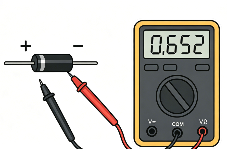
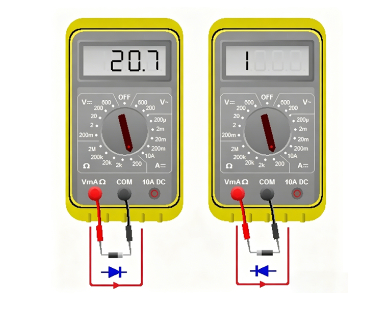
- Connect the test leads: Touch the red multimeter lead to the diode’s anode and the black lead to the diode’s cathode. This forward-biases the diode, allowing current to flow if the diode is functional.
- Record the reading: A functional silicon diode will display a voltage drop between 0.5V and 0.8V. Germanium diodes will display a lower voltage drop, between 0.2V and 0.3V. This voltage drop is a key indicator of a healthy diode, as it confirms the diode is conducting current in the forward direction.
- Reverse the test leads: Touch the red lead to the cathode and the black lead to the anode. This reverse-biases the diode, which should block current flow.
- Record the second reading: A healthy diode will display “OL” (overload) or a very high resistance value (infinite) when reverse-biased. This indicates the diode is blocking current in the reverse direction, as it should.
- Interpret the results: Compare the two readings to determine if the diode is functional. A good diode will show a voltage drop in forward bias and “OL” in reverse bias. Any deviation from this pattern indicates a faulty diode.
How to Test a Diode With an Analog Multimeter Correctly?
Analog multimeters do not have a dedicated diode test mode, so they use the resistance mode to test diodes. This requires careful range selection and interpretation of the needle position. Follow these steps to correctly test a diode with an analog multimeter.
- Prepare the multimeter: Check the battery, inspect test leads, set the dial to the resistance mode (Ω), and select a low range (R×10 or R×100). Short the test leads together and adjust the zero adjustment knob until the needle points to 0Ω on the resistance scale.
- Identify the diode’s anode and cathode: Use the physical markings or resistance test method to determine the diode’s terminals.
- Connect the test leads (forward bias): Touch the black lead to the diode’s anode and the red lead to the cathode. Note that analog multimeters have reverse polarity in resistance mode, the black lead is connected to the internal battery’s positive terminal, while the red lead is connected to the negative terminal. This is opposite to digital multimeters, so correct lead placement is critical.
- Record the needle position: A healthy diode will show a low resistance reading, with the needle deflecting significantly toward the 0Ω end of the scale. The exact resistance value will vary by diode type and multimeter range, but it should be consistent with the diode’s specifications (typically 100Ω–10kΩ for silicon diodes on R×10 range).
- Reverse the test leads (reverse bias): Touch the black lead to the cathode and the red lead to the anode. This reverse-biases the diode.
- Record the second needle position: A healthy diode will show a very high resistance reading, with the needle remaining near the infinite (∞) end of the scale. This indicates the diode is blocking current in the reverse direction.
- Interpret the results: A functional diode will have a low resistance in forward bias and high resistance in reverse bias. If the needle shows the same reading in both directions, or no deflection at all, the diode is faulty. Note that analog multimeter readings are less precise than digital ones, so focus on the relative difference between forward and reverse resistance.
How to Test a Diode Without a Diode Tester Using a Multimeter?
Many multimeters, especially older analog models or basic digital models, do not have a dedicated diode tester function. However, you can still test a diode using the multimeter’s resistance mode. This method is reliable and works for all diode types, as long as you follow the correct steps.
- Prepare the multimeter: Set the multimeter to the resistance mode (Ω) and select a low range (R×10 or R×100 for analog models; 200Ω or 2kΩ for digital models). For analog multimeters, zero the device by shorting the test leads and adjusting the zero knob.
- Disconnect the diode from the circuit: If the diode is in a circuit, remove one end to avoid interference from other components. This ensures the reading reflects only the diode’s resistance, not the entire circuit.
- Test forward bias resistance: Connect the test leads to the diode’s anode and cathode (follow polarity rules for your multimeter type). For digital multimeters, red lead to anode and black lead to cathode; for analog multimeters, black lead to anode and red lead to cathode. A healthy diode will show a low resistance reading (100Ω–10kΩ).
- Test reverse bias resistance: Reverse the test leads so the diode is reverse-biased. A healthy diode will show a very high resistance reading (infinite or “OL” on digital models).
- Verify with voltage drop (digital multimeters only): If your digital multimeter has a voltage mode, you can verify the diode’s functionality by measuring the forward voltage drop. Set the multimeter to DC voltage mode (2V range), connect the red lead to the anode and black lead to the cathode, and apply a small forward current (using a battery if needed). A reading of 0.5–0.8V (silicon) or 0.2–0.3V (germanium) confirms the diode is functional.
- Interpret the results: The key is to compare the forward and reverse resistance readings. A functional diode will have a significant difference between the two—low forward resistance and high reverse resistance. If the readings are similar or both are high/low, the diode is faulty.
How Many Ohms Should a Diode Read When Testing With a Multimeter?
The resistance reading of a diode when tested with a multimeter depends on whether the diode is forward-biased or reverse-biased, as well as the type of diode (silicon, germanium) and the multimeter’s range. There is no single “correct” ohm value, but there are standard ranges that indicate a healthy diode.
For forward-biased diodes, the resistance reading varies by diode type.Silicon diodes, the most common type, typically read between100Ω and 10kΩ when tested on a low resistance range (R×10 or R×100 for analog multimeters, 200Ω or 2kΩ for digital multimeters). This range is due to the diode’s forward voltage drop of 0.5–0.8V, which limits the current flow and results in a moderate resistance reading.
Germanium diodes have a lower forward voltage drop (0.2–0.3V), so their forward resistance reading is lower, typically between 50Ω and 5kΩ. This is because the lower voltage drop allows more current to flow, reducing the measured resistance.
For reverse-biased diodes, the resistance reading should be very high—effectively infinite. On digital multimeters, this is displayed as “OL” (overload). On analog multimeters, the needle will remain near theinfinite (∞) end of the scale. A reverse resistance reading that is low or close to the forward resistance reading indicates a faulty diode, as it is not blocking current in the reverse direction.
It is important to note that the exact resistance reading can vary based on the multimeter’s range. Using a higher resistance range (e.g., R×1k for analog multimeters) will result in a higher forward resistance reading, while a lower range will result in a lower reading. The key is not the exact value, but the difference between forward and reverse resistance, a healthy diode will have a large difference between the two.
How to Check If a Diode Is Damaged With a Multimeter?
Checking if a diode is damaged with a multimeter follows a step-by-step process, focusing on verifying the diode’s one-way conductivity (the core feature of a functional diode). Below are the clear, actionable steps to detect damage, with key details and fault types highlighted for easy reading (no H3 titles, directly listed):
- Prepare the Multimeter and Diode: Before testing, ensure accurate results by completing these preparations: Set the multimeter to the correct mode (digital: diode test mode; analog: resistance mode (Ω), low range R×10 or R×100); for analog multimeters, zero the device (short test leads and adjust zero knob to 0Ω, digital does not need this); isolate the diode (disconnect one end from circuit if applicable, turn off power and discharge capacitors); inspect test leads for damage and ensure secure connection to correct jacks (red to positive (+), black to common (COM)).
- Identify the Diode’s Anode and Cathode: Correct lead placement is critical (diodes conduct only one way). Use one of these methods: Check physical markings (most diodes have avisible band/line near the cathode, opposite end is anode); use a digital multimeter (diode test mode: touch red to one end, black to the other—0.5–0.8V for silicon means red is anode, black is cathode; “OL” means reverse leads).
- Test Forward Bias (Conduction Check): Test if the diode conducts current correctly (anode to cathode). Connect test leads properly: Digital multimeter – Red lead to anode, black lead to cathode; Analog multimeter – Black lead to anode, red lead to cathode (reverse polarity in resistance mode). Record the reading: Digital – healthy silicon diode shows 0.5–0.8V (germanium: 0.2–0.3V); Analog – needle deflects significantly toward 0Ω (100Ω–10kΩ for silicon on R×10 range).
- Test Reverse Bias (Blockage Check): Test if the diode blocks current (one-way valve function). Reverse the test leads: Digital – red to cathode, black to anode; Analog – black to cathode, red to anode. Record the second reading: Digital – healthy diode shows “OL” (overload) (infinite resistance); Analog – needle remains near infinite (∞) end of the scale.
- Interpret Results to Identify Damage: Compare forward and reverse readings—deviations indicate damage. Common damage types: • Open Circuit Damage: Reading is “OL” (digital) or infinite resistance (analog) in both forward and reverse bias; means the diode cannot conduct current at all (caused by excessive voltage/current burning the semiconductor). • Short Circuit Damage: Reading is low resistance (or voltage drop near 0V on digital diode mode) in both forward and reverse bias; means the diode acts like a wire (caused by voltage spikes or physical damage, risks damaging other components). • Leakage Damage (Partial Damage): Reverse resistance is lower than normal (e.g., 100kΩ instead of infinite), forward reading is normal; means the diode allows some reverse current (causes signal distortion/power loss, due to age, overheating, or manufacturing defects).
- Confirm Damage (Optional Verification): For extra certainty: Repeat forward and reverse tests 2–3 times (inconsistent readings = poor contact or partial damage); for digital multimeters, use voltage mode (2V range) to measure forward voltage drop (readings outside 0.5–0.8V silicon/0.2–0.3V germanium = damage); for zener diodes, reverse bias should show zener voltage (not “OL”)—if not, zener is damaged.
- Key Takeaway: A healthy diode has a clear difference between forward (low resistance/voltage drop) and reverse (high resistance/OL) readings. Any deviation means the diode is damaged and should be replaced.
Can You Test a Diode in Circuit When Using a Multimeter?
Testing a diode in circuit is possible, but it isnot always reliable. The presence of other components in the circuit, such as resistors, capacitors, or other diodes, can interfere with the multimeter’s readings, leading to false results. In most cases, it is best to remove the diode from the circuit for accurate testing.
If testing in circuit is necessary, follow these precautions to minimize interference. First, turn off all power to the circuit and discharge any capacitors. Capacitors can hold a charge and cause false readings or damage the multimeter. Next, identify the diode’s terminals and ensure no other components are connected directly across the diode—parallel resistors or other diodes can bypass the diode being tested, leading to incorrect resistance or voltage drop readings.
When testing in circuit with a digital multimeter in diode test mode, a healthy diode will still show a voltage drop of 0.5–0.8V (silicon) in forward bias and “OL” in reverse bias, provided no other components are interfering. If the reading is inconsistent or does not match the expected values, the interference from other components is likely the cause.
Analog multimeters are more prone to interference when testing in circuit, as their resistance readings are affected by parallel components. A resistor in parallel with the diode will lower the measured resistance, making a healthy diode appear faulty. For this reason, analog multimeters are not recommended for in-circuit diode testing unless the diode is isolated from other components.
In summary, while in-circuit testing is possible for quick checks,removing the diode from the circuit is the only way to ensure accurate results. This is especially important when diagnosing a faulty circuit, as false readings can lead to incorrect component replacement and further issues.
What Are the Common Mistakes When Testing a Diode With a Multimeter?
Even experienced technicians make mistakes when testing diodes, leading to incorrect results and wasted time. Avoid these common mistakes to ensure accurate diode test results every time.
- Incorrect lead polarity: Connecting the multimeter leads to the wrong diode terminals (anode and cathode) will result in reverse bias when forward bias is intended, and vice versa. This leads to false readings, such as “OL” in forward bias or a low resistance in reverse bias. Always double-check the diode’s terminals before connecting the leads.
- Testing a diode in a powered circuit: Forgetting to turn off power to the circuit or discharge capacitors can cause interference with the multimeter reading and pose a safety hazard. Even low voltage can affect the diode test, leading to false results. Always ensure the circuit is powered off and capacitors are discharged before testing.
- Using the wrong multimeter mode or range: For digital multimeters, using resistance mode instead of diode test mode can lead to inaccurate voltage drop readings. For analog multimeters, using a high resistance range (e.g., R×1k) can result in no visible needle deflection, making it impossible to interpret the reading. Always use the correct mode and range for diode testing.
- Not zeroing the analog multimeter: Failing to zero the analog multimeter before testing leads to inaccurate resistance readings. This is a common mistake that can make a healthy diode appear faulty or vice versa. Always short the test leads and adjust the zero knob before starting resistance-based diode tests.
- Ignoring diode type differences: Silicon and germanium diodes have different forward voltage drops and resistance readings. Assuming all diodes have the same specifications can lead to incorrect interpretations. Always consider the diode type when evaluating test results.
- Testing a diode in circuit without isolating it: As discussed earlier, other components in the circuit can interfere with the multimeter reading. Testing a diode without removing it from the circuit can lead to false results, especially if there are parallel resistors or capacitors.
- Using damaged test leads: Frayed or damaged test leads can cause poor contact, leading to inconsistent or incorrect readings. Always inspect the test leads before use and replace them if they are damaged.
FAQs About Diode Testing
Q1: Can a multimeter test all types of diodes, including LEDs and zener diodes?
A1: Yes, a multimeter can test all types of diodes, including LEDs, zener diodes, Schottky diodes, and rectifier diodes. The testing process is similar for all types, but there are minor differences. For LEDs, a forward voltage drop of 1.8–2.2V is normal (higher than silicon diodes). For zener diodes, reverse bias testing will show a voltage drop equal to the zener voltage (e.g., 5V for a 5V zener diode) instead of “OL.”
Q2: Why does my multimeter show different resistance readings for the same diode when using different ranges?
A2: Diodes are nonlinear components, meaning their resistance changes with the voltage and current applied. When using different multimeter ranges, the internal voltage and current of the multimeter change, leading to different resistance readings. This is normal—focus on the difference between forward and reverse resistance, not the exact value.
Q3: What if my digital multimeter does not have a diode test mode?
A3: If your digital multimeter does not have a dedicated diode test mode, use the resistance mode (200Ω or 2kΩ range) to test the diode. Follow the same steps as testing without a diode tester—check forward and reverse resistance. You can also use the voltage mode to measure the forward voltage drop, which is a more accurate indicator of diode functionality.
Q4: How do I know if a diode is a silicon or germanium type?
A4: The easiest way to distinguish between silicon and germanium diodes is by their forward voltage drop. Silicon diodes have a forward voltage drop of 0.5–0.8V, while germanium diodes have a drop of 0.2–0.3V. Use a digital multimeter in diode test mode to measure the forward voltage drop and identify the diode type.
Q5: Can a diode be partially damaged, or is it either good or bad?
A5: Diodes can be partially damaged, most commonly as leaky diodes. A leaky diode allows some reverse current to flow but not enough to be considered a short circuit. This can cause subtle issues in the circuit, such as signal distortion or power loss. Testing both forward and reverse bias will reveal leakage, as the reverse resistance will be lower than normal.