PCB manufacturing PCB manufacturing
Home > Blog

ai accelerator pcb

OAM PCB Explained: How It Works in AI Servers
Friday, August 21st, 2026

OAM PCB is the accelerator-module circuit board used to connect high-density AI compute with a server's power, high-speed links, management, and cooling systems. OAM means OCP Accelerator Module; the module normally works with a Universal Base Board (UBB) rather than operating as a stand-alone processor board. This guide shows how the parts fit together, how OAM differs from SXM, and which electrical, thermal, mechanical, fabrication, and assembly requirements matter to a buyer.

EBest Circuit (Best Technology) supports AI accelerator PCB projects with high-layer and HDI fabrication, controlled impedance, component sourcing, BGA assembly, AOI, X-ray inspection, and customer-defined test coordination. If you are evaluating an OAM PCB, send your current board requirements to sales@bestpcbs.com for an initial manufacturability discussion.

OAM PCB
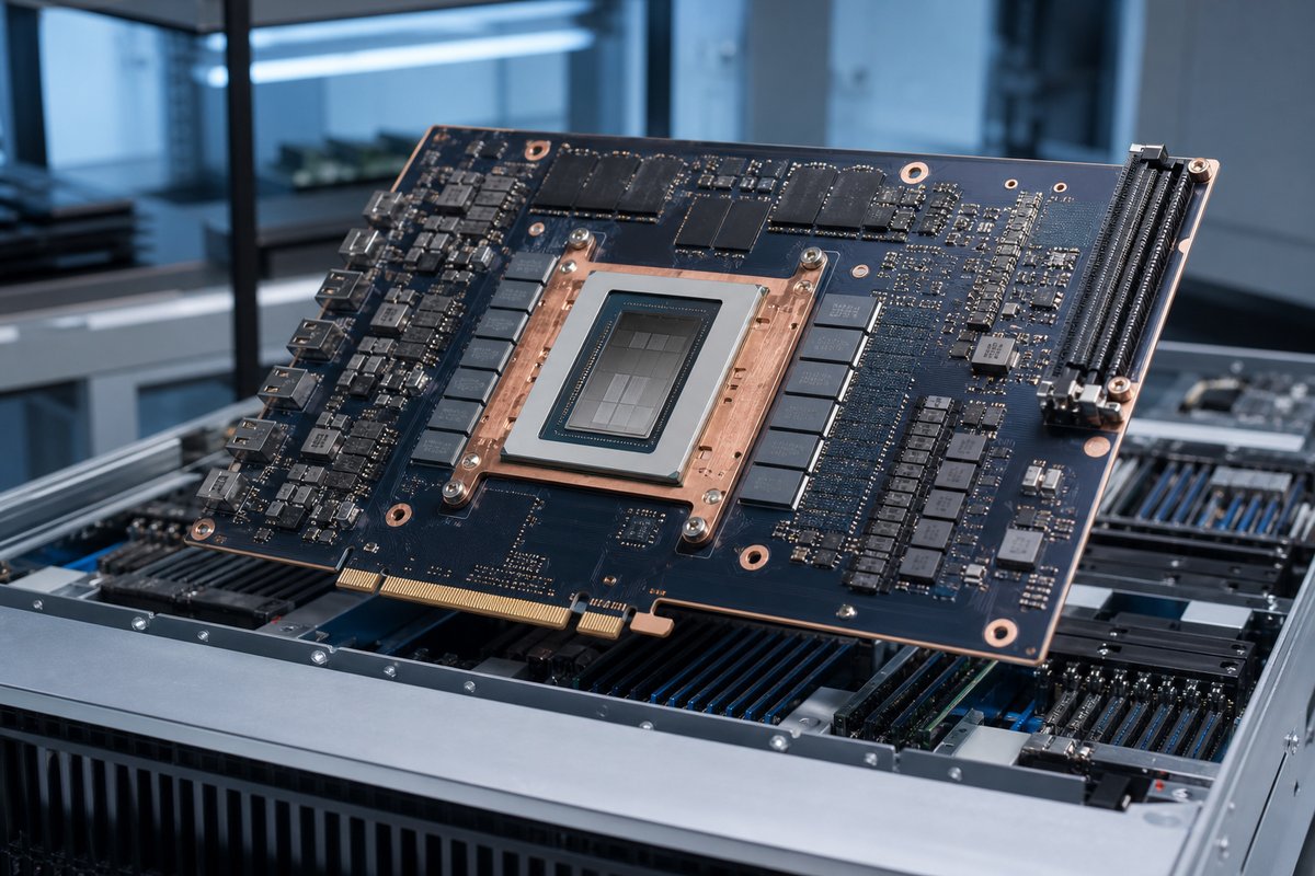
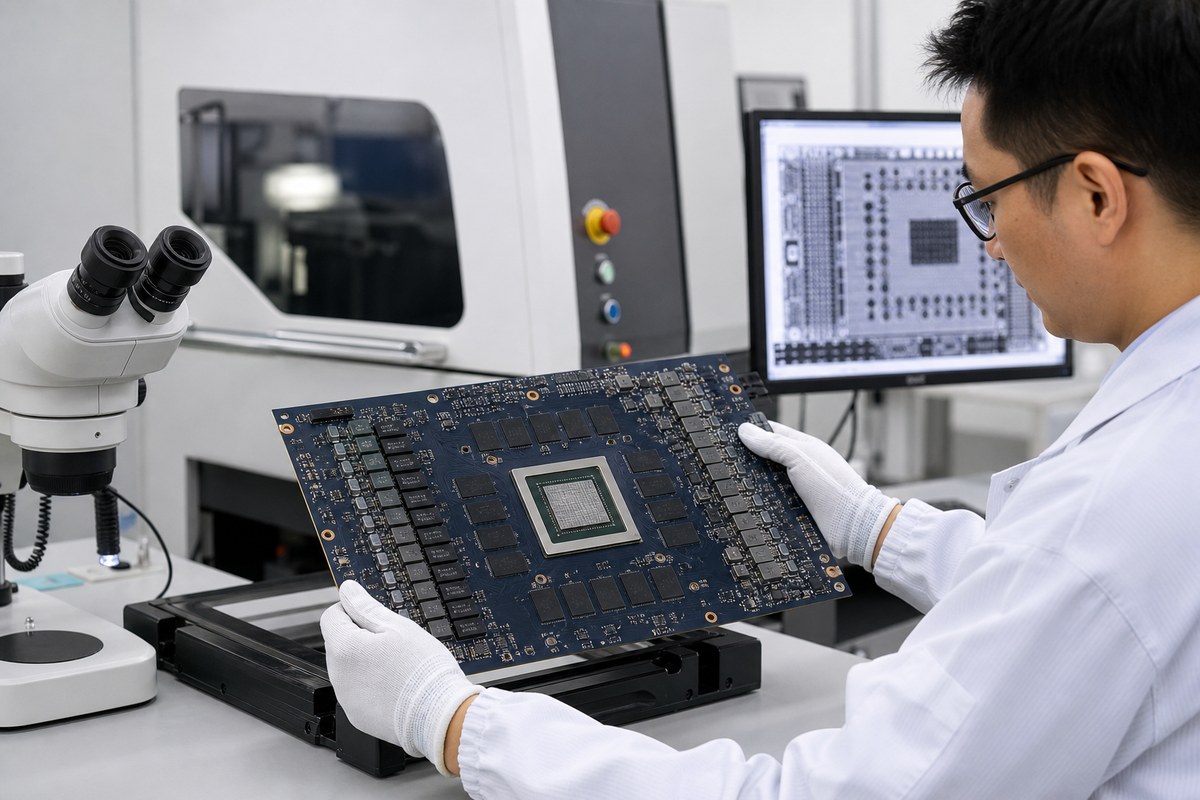
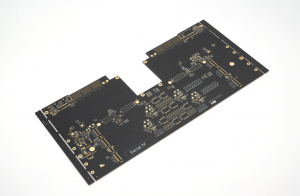
OAM accelerator PCB module in an AI server platform.

What Is an OAM PCB?

An OAM PCB is the printed circuit board used in an OCP Accelerator Module. It carries an AI accelerator device and the supporting circuitry required to power, manage, connect, and cool that device inside a compatible server platform.

  • Compute: a GPU, ASIC, NPU, FPGA, or another parallel processor.
  • Local support: memory, voltage regulation, clocks, management devices, and sensors.
  • System connection: the connector and mechanical interfaces that link the module to a compatible baseboard and cooling assembly.

OAM defines a form factor and interface framework, not a processor brand or a fixed PCB construction. The actual layer count, materials, vias, components, and tests still depend on the accelerator, power envelope, cooling approach, UBB, and product specification.

How Does an OAM PCB Work in an AI Server?

Inside an AI server, the OAM PCB acts as the local platform for one accelerator. It receives power and management connections from the system, provides the short electrical paths needed around the accelerator and memory, and connects high-speed links to the UBB.

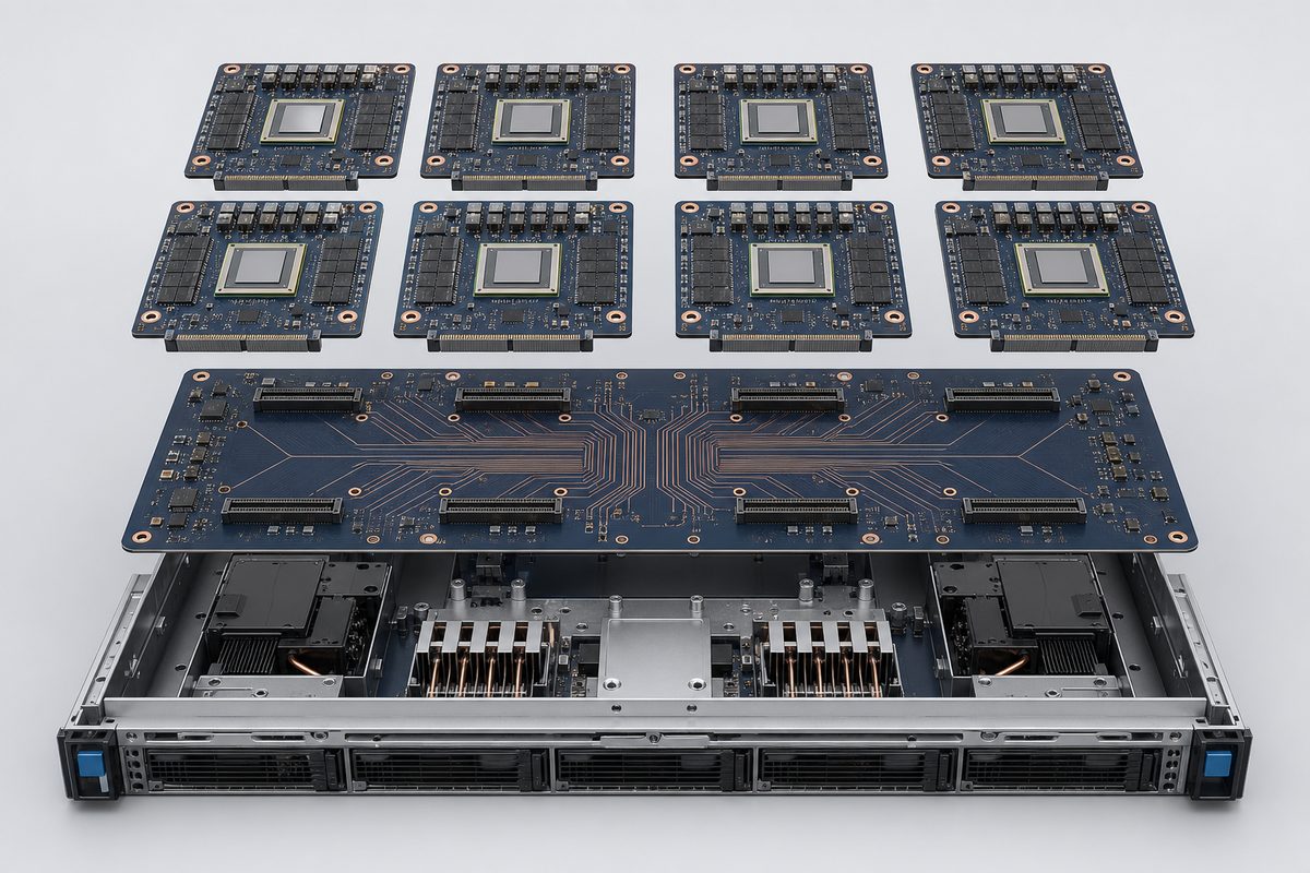
The UBB brings multiple OAM modules together. It distributes power and management signals and provides the physical interconnect fabric between accelerators. Depending on the system architecture, those accelerator-to-accelerator links can support the very high data movement needed for training or inference workloads.

A simplified data path is:

  • The host server sends work and data toward the accelerator platform.
  • The UBB routes high-speed links, power, and control connections to each OAM module.
  • The OAM PCB supports the accelerator, local memory, power conversion, sensing, and module-level interfaces.
  • Cooling hardware removes heat from the accelerator and other high-power components.

This division lets the module, baseboard, host, power system, and cooling system be developed as coordinated building blocks. It also means an OAM PCB cannot be evaluated in isolation: its connector geometry, mounting features, power inputs, thermal stack, and high-speed interfaces must match the intended platform.

What Does the OAM Architecture Include?

Although implementations vary, the OAM architecture normally combines several functional groups on one dense PCB.

  • Accelerator package: the main GPU, ASIC, NPU, FPGA, or other compute device.
  • Local memory: high-bandwidth or other memory devices placed close to the accelerator when required by the processor architecture.
  • Power delivery: voltage regulators, inductors, capacitors, current sensing, and power-control circuits that convert the module input into multiple low-voltage rails.
  • High-speed interfaces: differential channels connecting the accelerator to other modules, the host, and management resources through the module connector.
  • Management and monitoring: controllers, EEPROMs, clocks, temperature sensors, voltage monitors, and service interfaces.
  • Mechanical and thermal interfaces: mounting holes, keep-out areas, stiffeners, heatsink contact zones, and the flatness needed for reliable connector engagement and cooling contact.

These groups compete for board area and influence one another. A larger power stage changes copper distribution and thermal behavior. Dense high-speed escape routing can require HDI structures. A heavy heatsink can increase mechanical loading. The architecture must therefore be translated into one coordinated stackup, layout, fabrication, assembly, and cooling plan.

How Do OAM Modules and UBBs Work Together?

An OAM module is the accelerator board; a UBB is the baseboard that hosts and connects multiple modules. The two boards perform different jobs but operate as one platform.

Platform part Primary role What must match
OAM module Carries one accelerator and its local support circuits. Connector, power, lane map, cooling, and mounting.
UBB Hosts and links multiple OAM modules. Sockets, routing, current capacity, management, and clearances.
AI server Combines compute, power, cooling, firmware, and software. Power sequence, thermal capacity, service access, and validation.

A useful way to picture the relationship is: AI server -> UBB -> multiple OAM modules -> accelerator and local memory on each module.

For example, when eight accelerator modules are installed on one UBB, a connector-position error on one OAM PCB can prevent reliable mating, while an incorrect lane map or channel-loss assumption can affect communication beyond that single module. The OAM and UBB suppliers therefore need controlled interface drawings and the same revision baseline.

OAM PCB
Eight OAM modules connect through a UBB inside an AI server tray.

OAM vs SXM: What Is the Difference?

OAM and SXM are both used for high-performance accelerator modules, but they come from different platform ecosystems. OAM is associated with the Open Compute Project and is intended to support an open, multi-vendor infrastructure. SXM is a proprietary NVIDIA module format used in selected NVIDIA server platforms.

Decision area OAM SXM
Ecosystem Open, OCP/OAI-oriented. Proprietary NVIDIA platform.
Choose when The system uses an OAM-compatible accelerator and UBB. The selected NVIDIA platform requires SXM.
Baseboard OAM-compatible UBB. Designated NVIDIA baseboard.
Can they swap? No; the complete platform must match. No; the complete platform must match.

The two formats should not be treated as drop-in replacements. Moving a design from one to the other can affect the module PCB, baseboard, firmware, cooling assembly, power delivery, chassis, and system validation. The form-factor decision belongs at the platform architecture stage, before PCB fabrication data is released.

What Are the PCB Design Requirements for OAM-Compatible Systems?

An OAM-compatible system must carry fast signals, high current, dense packages, and substantial thermal and mechanical loads at the same time. The PCB design requirements are therefore interconnected.

  • Stackup and materials must support the required channel loss, impedance, layer count, thickness, and fabrication capability.
  • Differential pairs need controlled geometry, continuous reference planes, suitable spacing, and a via strategy that limits discontinuities.
  • Large packages and dense connectors may require blind or buried vias, microvias, via-in-pad, filled vias, and back drilling.
  • Power and ground structures must carry the module current while controlling voltage drop, noise, and localized heating.
  • Copper distribution and layer construction must support board flatness and reduce assembly warpage risk.
  • Connector footprints, mounting holes, heatsink interfaces, keep-outs, and board edges must follow the mechanical definition of the target platform.

The most useful design review looks at the complete path: accelerator package breakout, on-module routing, connector launch, UBB routing, and the destination device. A locally correct trace can still fail if the combined channel exceeds its loss or discontinuity budget.

What Power and Thermal Requirements Shape an OAM PCB?

OAM PCBs combine high power density with strict mechanical and signal-integrity requirements. Power and thermal design therefore shape the physical PCB, not just the component selection.

Requirement group What shapes the PCB What the customer must define
Power Planes, copper, vias, decoupling, and regulator layout. Input power, rail current, voltage drop, transients, and sequence.
Thermal Heat spreading, component spacing, and cooler interface. Cooling method, contact area, temperature limits, and test conditions.
Mechanical Thickness, stiffeners, mounting, alignment, and flatness. Datums, mounting load, keep-outs, tolerances, and tray limits.

These requirements must be reviewed together. More copper may improve current capacity but can change etching, lamination, impedance geometry, flatness, and reflow behavior. A large cooling assembly may remove heat effectively but still create board strain if the mounting stack is not coordinated.

The PCB manufacturer can review manufacturability and material implications, but final power integrity, cooling design, and server validation remain system responsibilities.

How Are PCBs Fabricated and Assembled for OAM Modules?

OAM modules are commonly advanced multilayer assemblies, but the exact process should follow the released design rather than a generic OAM recipe.

  • Fabrication review: confirm materials, copper, impedance geometry, via structure, lamination, registration, back drilling, thickness, flatness, and finish.
  • Assembly planning: account for large BGAs, memory, power components, connector coplanarity, thermal mass, moisture control, paste, placement, and reflow.
  • Verification plan: select bare-board electrical test, impedance testing, SPI, AOI, X-ray, dimensional checks, and customer-defined functional tests according to the real risks.

No single inspection method proves the whole module. The evidence plan should match the likely failure modes and the test points that are actually accessible.

EBest Circuit (Best Technology) can support manufacturability review, material coordination, PCB fabrication, component sourcing, BGA assembly, AOI, X-ray inspection, and customer-defined testing coordination. Accelerator architecture, firmware, system cooling, regulatory compliance, and final server qualification remain with the customer and its platform partners.

OAM PCB
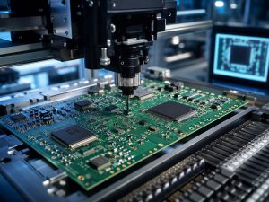
Inspection of a high-density OAM PCB assembly in an electronics laboratory.

Where Is OAM PCB Technology Used?

OAM PCB technology is used where systems need dense, modular accelerator computing. The most visible applications are AI training servers and high-performance computing platforms, but the same infrastructure can also support inference, data analytics, scientific computing, and other workloads built around compatible accelerator modules.

  • AI training servers that need several tightly connected accelerator modules.
  • High-performance computing clusters handling scientific or engineering workloads.
  • Cloud and enterprise AI infrastructure designed around serviceable accelerator trays.
  • Inference and data-analytics platforms that benefit from dense modular compute.
  • Specialized compute appliances built around an OAM-compatible accelerator ecosystem.

OAM is not automatically the best format for every AI product. PCIe cards may be simpler for lower-power or broadly compatible add-in acceleration, while embedded modules may fit edge systems with tighter space and power limits. OAM becomes most relevant when the platform benefits from high accelerator density, strong module-to-module communication, serviceable modular hardware, and coordinated power and cooling.

How to Choose an OAM PCB Manufacturer?

An OAM PCB manufacturer should be evaluated against the released board requirements, not against a generic list of advanced capabilities.

Evaluation stage What to confirm Why it matters
1. Platform fit Understands the OAM/UBB interface and board requirements. Prevents interface assumptions from reaching production.
2. Process fit Covers the required HDI, impedance, assembly, and inspection steps. Keeps fabrication and assembly decisions aligned.
3. Build control Controls material, stackup, BOM, files, and test revisions. Reduces prototype-to-production revision drift.

The best supplier is not necessarily the one that claims the highest layer count. It is the one that can explain how the specific OAM design will be built, where its process margins are tight, what evidence will be delivered, and which responsibilities remain with the system developer.

For project-specific review, send the released Gerber or ODB++ data, stackup, fabrication drawing, BOM, placement data, assembly drawing, connector and mechanical definitions, and test requirements to sales@bestpcbs.com.

FAQs About OAM PCB

What does OAM mean in PCB hardware?

OAM means OCP Accelerator Module. In PCB hardware, it describes an accelerator-module form factor and interface framework developed in the Open Compute Project ecosystem.

Is an OAM PCB the same as a UBB?

No. The OAM PCB carries one accelerator module. The Universal Base Board hosts and connects multiple OAM modules and provides shared interconnect, power, management, and mechanical integration.

Is OAM the same as NVIDIA SXM?

No. Both are accelerator-module formats, but OAM belongs to an open OCP/OAI ecosystem while SXM is a proprietary NVIDIA platform. Their interfaces and system requirements are not interchangeable.

Why are OAM PCBs difficult to manufacture?

They can combine high layer counts, low-loss materials, HDI vias, dense high-speed routing, high-current power structures, large BGA packages, strict flatness, and demanding thermal hardware on one assembly.

What should be reviewed before building an OAM PCB?

Review the platform specification, board and UBB revisions, stackup, impedance and loss targets, via structure, power inputs, connector and mechanical definitions, thermal stack, BOM, assembly data, and inspection and test requirements.

Planning an OAM PCB or another AI accelerator PCB? Send your current design package or project questions to sales@bestpcbs.com. EBest Circuit (Best Technology) can review the PCB fabrication, sourcing, assembly, inspection, and customer-defined test scope for your build.

You may also like

Practical AI Accelerator PCB Manufacturing Guide
Thursday, August 20th, 2026

AI accelerator PCB combines fast data channels, high current, dense packages, and demanding thermal interfaces on one board. A weakness in the stackup, via structure, material choice, assembly process, or inspection plan can cause signal loss, unstable power, solder defects, overheating, or an expensive redesign.

EBest Circuit (Best Technology) supports these projects from manufacturability review and material coordination through PCB fabrication, component sourcing, BGA assembly, X-ray inspection, and customer-defined testing. Keeping these stages with one manufacturing partner helps maintain the same revision, stackup, component, and quality requirements from prototype to repeat production.

If you are preparing an AI accelerator PCB for quotation or production, send your Gerber data, stackup, BOM, assembly files, and test requirements to sales@bestpcbs.com for a project-specific review.

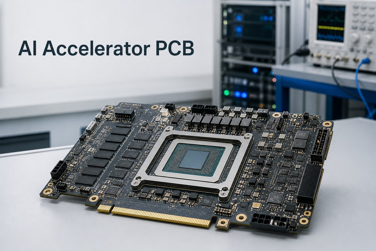
AI accelerator PCB
AI accelerator PCB manufacturing for high-speed computing hardware.

What Is an AI Accelerator PCB?

An AI accelerator PCB is the circuit board that carries or connects specialized processors used to accelerate artificial-intelligence workloads. The processor may be a GPU, NPU, ASIC, FPGA, or another dedicated computing device.

The PCB provides the physical platform for:

  • High-speed connections to the host, memory, and other accelerators.
  • Stable power for the processor, memory, and supporting circuits.
  • Management, clock, control, and communication devices.
  • Mechanical attachment to connectors, stiffeners, heatsinks, and the enclosure.
  • Component assembly, inspection, programming, and testing.

Depending on the system, the product may be a PCIe accelerator card, an embedded AI module, an OAM-style module, a carrier or baseboard, or a custom computing assembly. The PCB is not the accelerator chip itself; it is the high-density electrical and mechanical foundation that allows the accelerator to operate inside the finished product.

What Are the Key Requirements for AI Accelerator PCBs?

An effective AI accelerator PCB must handle high-speed data, high current, dense interconnection, thermal stress, and reliable assembly at the same time.

The main requirements are:

  • Controlled high-speed channels: The stackup, impedance, routing layers, vias, and connectors must support the customer’s channel targets.
  • Stable power delivery: Power and ground structures must carry the required current without excessive voltage drop or localized heating.
  • Suitable PCB materials: Laminates, copper profiles, and dielectric thicknesses must match signal-loss, thermal, mechanical, availability, and cost needs.
  • High-density routing: Fine-pitch devices and connectors may require HDI, blind or buried vias, via-in-pad, or back drilling.
  • Thermal and mechanical compatibility: Board thickness, copper distribution, mounting holes, stiffeners, and heatsink interfaces must work together.
  • Repeatable PCBA: Stencil design, component handling, placement, reflow, warpage control, and inspection must suit large or fine-pitch packages.
  • Defined quality evidence: Bare-board tests, AOI, X-ray, electrical tests, and functional tests should match the risks of the product.

These requirements are interdependent. Increasing copper for power, for example, can change etching, lamination, impedance geometry, reflow behavior, and board flatness. The best result comes from reviewing the complete board rather than treating each specification separately.

Why Are AI Accelerator PCBs Difficult to Manufacture?

AI accelerator PCBs are difficult to manufacture because several advanced features often appear on the same board, leaving less room for process variation.

Common combinations that increase difficulty include:

  • Many signal, power, and ground layers in a controlled finished thickness.
  • Low-loss materials combined with fine traces and tight impedance control.
  • Blind, buried, stacked, filled, or back-drilled vias.
  • Dense accelerator, memory, and connector breakout areas.
  • Large copper areas next to fine-pitch circuitry.
  • Large BGAs or modules with high thermal mass and warpage sensitivity.

A thicker multilayer board may improve routing and power distribution but make small-hole plating more difficult. Thin HDI dielectrics may improve package escape but require additional lamination cycles. Heavy copper can carry more current but may affect copper balance, etching, and assembly heat.

The challenge is therefore not simply producing one advanced feature. It is controlling registration, plating, lamination, impedance, flatness, and assembly when all those features interact. Early engineering review helps identify which combination is likely to control yield, cost, and lead time before material is committed.

What Stackup and Materials Are Used for AI Accelerator PCBs?

AI accelerator PCBs typically use multilayer or HDI stackups with dedicated signal, reference, power, and ground layers. The exact construction depends on channel length, interface speed, routing density, power demand, via architecture, board thickness, and mechanical form factor.

A practical stackup may include:

  • Signal layers placed next to continuous reference planes.
  • Closely coupled power and ground layers where required by the power-integrity design.
  • HDI build-up layers for dense package or connector escape.
  • Mechanically drilled through-holes for lower-density connections and structural strength.
  • Back drilling where unused plated-through-hole stubs would create excessive signal discontinuity.

Low-loss materials are often used for long or fast channels, while hybrid stackups may place higher-performance material only where it provides a clear electrical benefit. Material selection should consider more than a published Dk or Df value.

DecisionCustomer priorityManufacturing effect
Signal layersLoss and impedanceLayer count and dielectric geometry
Power layersCurrent and voltage dropCopper weight and balance
Via structurePackage escape and stub limitsDrill and lamination sequence
LaminateElectrical and thermal needsAvailability, processing, and cost
ThicknessConnector and mechanical fitStackup tolerance and flatness

The production stackup should identify actual materials, dielectric thicknesses, finished copper, via structures, controlled impedances, and tolerances. If the fabricator proposes a material or geometry change, the customer’s electrical owner should evaluate its effect before the design is built.

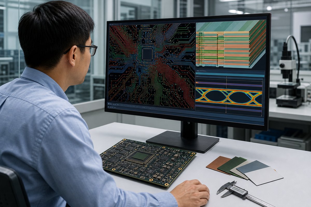
AI accelerator PCB
Multilayer stackup, low-loss materials, and controlled interconnect structures.

What High-Speed Requirements Affect AI Accelerator PCB Manufacturing?

High-speed requirements affect material selection, stackup geometry, copper profile, impedance control, via design, back drilling, and fabrication tolerances.

Three areas deserve particular attention:

  • Channel loss: Laminate loss, copper roughness, trace length, and via transitions determine how much of the signal reaches the receiver.
  • Impedance discontinuity: Neck-downs, antipads, connectors, layer changes, and unused via stubs can create reflections.
  • Skew and crosstalk: Pair geometry, reference planes, glass weave, spacing, and routing consistency affect timing and noise.

The fabrication drawing should clearly identify controlled-impedance structures, target values and tolerances, coupon requirements, and any back-drill or residual-stub limits. The fabricator should calculate impedance using the proposed production materials and finished copper rather than generic design values.

TDR coupon results can show whether selected structures meet the agreed impedance requirement. They do not replace the customer’s full-channel simulation, eye-diagram analysis, or protocol validation. The manufacturing value is consistency: the built geometry and test evidence should match the approved stackup.

What Power Requirements Affect AI Accelerator PCB Manufacturing?

AI accelerator PCB manufacturing must support high current, rapid load changes, low-voltage rails, and concentrated heat without creating excessive voltage drop or unreliable copper structures.

Board-level power affects:

  • The number and location of power and ground layers.
  • Copper weight, plane shape, neck-down areas, and connector transitions.
  • The quantity and arrangement of power and thermal vias.
  • Decoupling-component placement and available routing space.
  • PCB thickness, copper balance, flatness, and assembly heat.
  • Heatsink, stiffener, mounting, and airflow interfaces.

Even a short narrow section in a high-current path can create voltage drop and local heating. Likewise, adding heavy copper without considering balance can make fabrication and reflow less uniform. Power integrity therefore needs to be translated into practical plane geometry, copper construction, and via structures before the stackup is finalized.

EBest Circuit can review whether the released copper, via, material, and mechanical features are manufacturable. The customer or its design partner remains responsible for load assumptions, voltage-drop limits, simulation targets, and final cooling-system performance.

Why Is HDI Important for AI Accelerator PCBs?

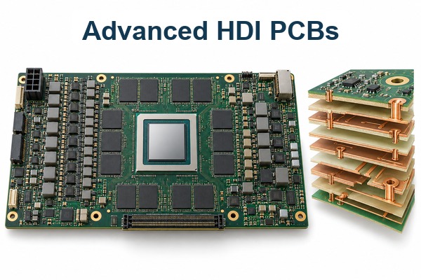
HDI is important because dense accelerator packages and high-pin-count connectors can require smaller vias and more routing space than conventional through-hole structures provide.

HDI can help by:

  • Escaping fine-pitch packages with shorter, smaller interconnects.
  • Keeping through-holes from blocking multiple inner routing layers.
  • Providing more direct access to power and ground structures.
  • Reducing the electrical length of selected layer transitions.
  • Supporting compact modules and dense connector areas.

However, HDI should not be added simply because the product is an AI board. Blind microvias, stacked structures, via-in-pad, copper filling, and repeated sequential lamination increase cost and process sensitivity. A staggered structure or a combination of microvias and mechanically drilled vias may be more practical when routing allows it.

The objective is the least complex via architecture that still meets package escape, signal, power, reliability, thickness, and cost requirements. Microvia depth, diameter, land size, stacking, filling, registration, and reliability expectations should be reviewed as one structure.

What Makes AI Accelerator PCB Assembly Difficult?

AI accelerator PCB assembly is difficult because large devices, fine-pitch joints, high component density, heavy copper, and uneven thermal mass must pass through one stable assembly process.

Major assembly risks include:

  • BGA warpage: A large package and the PCB may bend differently during reflow, increasing open-joint or head-in-pillow risk.
  • Hidden solder joints: BGAs and bottom-terminated devices cannot be fully assessed by visual inspection alone.
  • Uneven heating: Heavy copper, large ground areas, connectors, and heatsinks can create different heating and cooling rates.
  • Paste-volume conflict: Fine-pitch devices and large thermal pads may require different stencil strategies.
  • Moisture exposure: Improper storage or handling of moisture-sensitive devices can damage packages during reflow.
  • Mechanical loading: Stiffeners, heatsinks, and mounting hardware can stress the assembled board if their sequence or torque is not controlled.

Consider an accelerator card with a large BGA, low-loss multilayer PCB, back-drilled high-speed vias, and high-current power stages. If the stackup changes after electrical approval, or the reflow plan ignores board and package warpage, the prototype may pass continuity testing yet fail under load or temperature cycling.

For this type of project, EBest Circuit can coordinate the approved BOM, component handling, stencil review, placement, reflow, AOI, X-ray, and customer-defined test steps under one revision-controlled build. Programming files, functional limits, fixtures, and final product acceptance requirements should be supplied or approved by the customer.

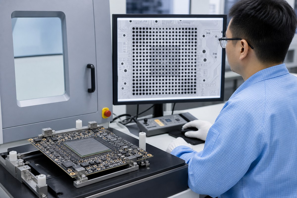
AI accelerator PCB
BGA assembly and X-ray inspection for an AI accelerator PCB.

How Are AI Accelerator PCBs Inspected and Tested?

AI accelerator PCBs are inspected in stages because bare-board defects, placement errors, hidden solder joints, and functional failures require different methods.

Bare PCB inspection

  • AOI checks the patterned layers for selected opens, shorts, and image defects.
  • Electrical testing checks network continuity and isolation.
  • Impedance coupons and TDR verify agreed controlled structures.
  • Dimensional or microsection records may be added when specified.

Assembly inspection

  • SPI can check solder-paste deposition when included in the inspection plan.
  • AOI checks component presence, position, polarity, and visible solder joints.
  • X-ray examines hidden BGA and bottom-terminated solder joints.
  • First-article records confirm the approved revision and assembly condition.

Electrical and functional testing

  • ICT or boundary scan can detect defined assembly and connectivity faults.
  • Programming verification confirms that the specified device image was loaded.
  • Fixture-based functional tests check customer-defined operating conditions.
  • Burn-in or environmental screening is used only when the project specification requires it.

No single result proves the complete product. Before production, the customer and supplier should agree which reports are required, how sampling will work, what constitutes acceptance, and how failures will be handled. This avoids receiving a stack of inspection reports that does not answer the product’s real risks.

How to Choose an AI Accelerator PCB Manufacturer?

Choose an AI accelerator PCB manufacturer by checking whether it can control the complete combination of stackup, materials, HDI features, assembly risks, and quality evidence required by your board.

Ask each candidate to provide:

  • A producible stackup with named materials and realistic alternatives.
  • DFM feedback on the features most likely to affect yield or reliability.
  • A clear plan for impedance control, HDI, back drilling, copper balance, and board flatness where applicable.
  • BGA assembly, moisture handling, warpage, reflow, AOI, and X-ray controls.
  • Component sourcing and traceability controls for PCBA orders.
  • Defined test methods, sampling, acceptance criteria, and report outputs.
  • A revision-control process covering quotation, fabrication, assembly, programming, and testing.

EBest Circuit’s advantage is the ability to connect these stages rather than treating the PCB, components, assembly, and inspection as unrelated purchases. One engineering and production path can help reduce stackup mismatches, uncontrolled material substitutions, BOM revision errors, and gaps between assembly risk and inspection evidence.

Send the same controlled data package to each supplier so quotations are comparable. A useful quotation should identify the material system, stackup assumptions, special processes, tooling, inspection, test scope, lead-time conditions, and unresolved questions—not only a headline price.

FAQs About AI Accelerator PCB

What files are needed for an AI accelerator PCB quotation? Provide Gerber or approved fabrication data, a fabrication drawing, drill files, stackup or impedance requirements, dimensions, tolerances, quantity, and schedule. For assembly, also provide the BOM, centroid data, assembly drawings, approved substitutions, programming needs, and test requirements.

Can one supplier handle both AI accelerator PCB fabrication and assembly? Yes, if the supplier has the required fabrication, sourcing, assembly, inspection, and test capabilities. Using one coordinated partner can reduce revision mismatches between the bare PCB and PCBA stages.

How are large BGA solder joints inspected? AOI checks visible placement and surrounding joints, while X-ray is used for hidden BGA connections. Acceptance criteria should be defined for the package, board, and product rather than inferred from an image alone.

Can an alternative low-loss laminate be used? Sometimes, but it should be evaluated for dielectric properties, copper profile, available thicknesses, thermal behavior, process compatibility, lead time, and its effect on the approved impedance and loss model.

What affects AI accelerator PCB prototype cost and lead time? The main drivers include layer count, material availability, HDI and lamination cycles, via filling, back drilling, impedance requirements, board size, copper weight, component availability, assembly complexity, inspection, testing, quantity, and engineering review.

A reliable AI accelerator PCB depends on the stackup, high-speed channels, power delivery, HDI structure, assembly process, and inspection plan working together. EBest Circuit (Best Technology) can support the project from manufacturability review and PCB fabrication through sourcing, BGA assembly, X-ray inspection, and customer-defined testing.

Send your fabrication data, stackup, BOM, and test requirements to sales@bestpcbs.com for a project-specific AI accelerator PCB review and quotation.
You may also like

AI Server PCB Design: Stackup, Signal Integrity and Power Delivery
Thursday, August 13th, 2026

AI server PCB design must coordinate high-speed channels, dense accelerator routing, large transient currents, thermal limits, and manufacturable stackup details from the start. A board can pass ordinary design-rule checks and still fail if its material model, via structure, reference planes, power delivery network, and released fabrication data describe different electrical assumptions.

The practical goal is not to choose the highest layer count or the most expensive laminate. It is to convert the system architecture into a controlled board structure that can be simulated, fabricated, assembled, measured, and revised without losing traceability.

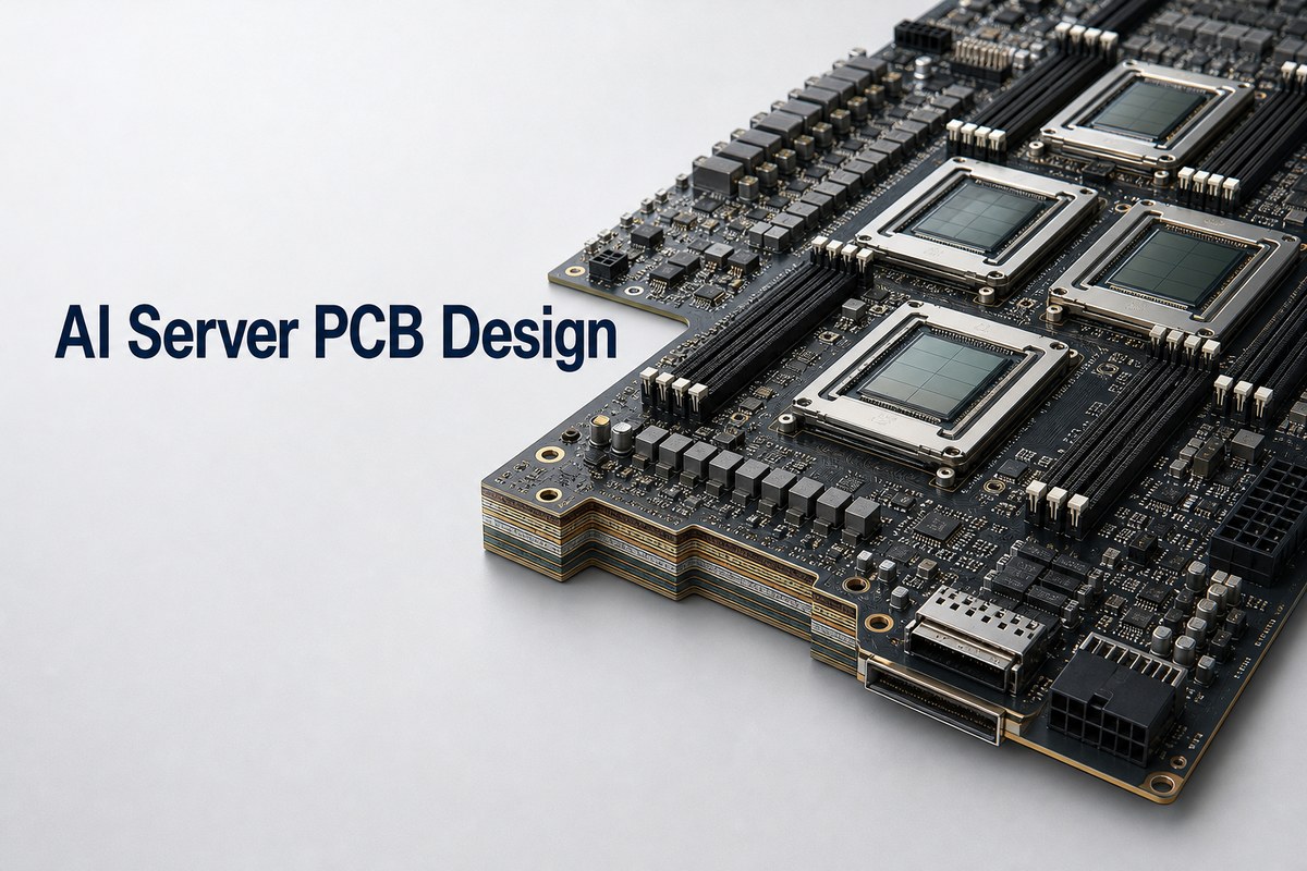
AI Server PCB Design on a high-density accelerator motherboard

What Is AI Server PCB Design?

AI server PCB design is the board-level engineering used for accelerator cards, server motherboards, backplanes, switch boards, power boards, and related high-performance computing hardware. It connects processors, accelerators, memory, storage, network interfaces, power conversion, management controllers, and mechanical interfaces within defined electrical and thermal margins.

The phrase should not be confused with AI-assisted PCB software. Here, “AI” describes the server workload and hardware architecture. The design challenge comes from dense interconnects, high aggregate bandwidth, fast current steps, large packages, and tight airflow or cold-plate constraints.

How Does an AI Server PCB Differ from a Standard Server Board?

An AI server PCB usually concentrates more high-speed lanes and higher power density around accelerators than a general-purpose server board. The exact difference depends on the platform, but the following design domains commonly become more tightly coupled.

Design Domain AI Server PCB Focus Release Evidence
High-speed links Loss, crosstalk, return paths, transitions, and connector channels Channel model, routing rules, and measured validation plan
Power delivery Low impedance across frequency, transient response, and current sharing PDN targets, plane geometry, capacitor strategy, and power test points
Density BGA escape, microvias, via-in-pad, and layer transitions Stackup, drill table, via structure, and fabrication feedback
Thermal and mechanical Package heat, copper distribution, stiffeners, connectors, and cooling interfaces Mechanical model, thermal assumptions, and assembly constraints

Which Board Architecture Should Be Defined First?

The board role must be defined before the stackup because a motherboard, accelerator card, backplane, and power board do not share the same routing or verification priorities. Start by mapping the interfaces, package transitions, connectors, board outline, cooling method, and power entry points.

  • Identify every high-speed interface and its end-to-end channel boundary.
  • Separate on-board routing from connector, cable, package, and mezzanine contributions.
  • Map voltage rails, expected current steps, conversion stages, and return paths.
  • Lock connector zones, keep-outs, fastener locations, stiffeners, and cooling interfaces.
  • Assign owners for SI, PI, thermal, mechanical, PCB, assembly, and validation decisions.

This architecture map prevents a local layout improvement from consuming margin needed elsewhere in the system.

How Should the AI Server PCB Stackup Be Planned?

The stackup should be derived from routing density, reference-plane continuity, impedance structures, power distribution, via transitions, total thickness, and fabricator constraints. There is no universal layer count for an AI server board.

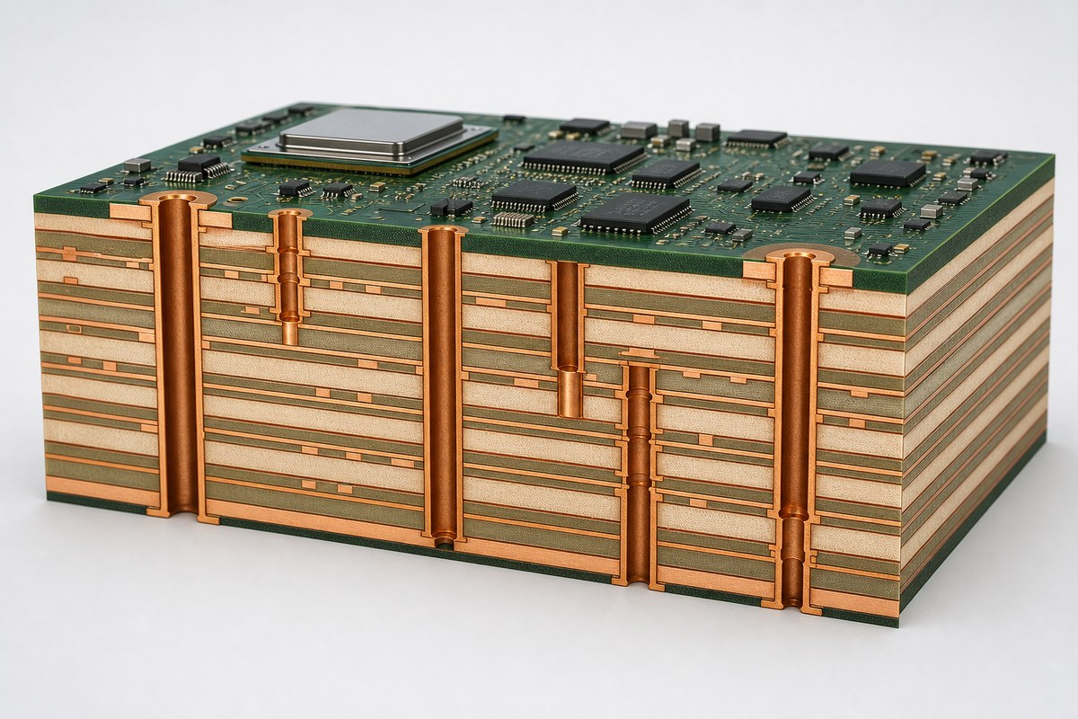
Route critical signals next to continuous reference planes and minimize unnecessary reference changes. Power and ground planes should support the PDN strategy, while dielectric choices and finished copper thickness must match the values used in simulation. A proposed stackup is not controlled until the layout rules, impedance table, drill definitions, and fabrication drawing all describe the same build.
Cutaway of a multilayer AI server PCB stackup with through holes and microvias

For a focused introduction to a related commercial application, see our AI server PCB manufacturing overview.

Which Materials Support High-Speed AI Server Links?

Material selection should follow the channel loss budget, operating frequency range, stackup construction, copper profile, thermal exposure, and supply availability. A laminate name by itself is not an electrical model.

Record the source and test conditions for dielectric constant and dissipation factor. Then align those assumptions with resin content, glass style, finished dielectric thickness, copper roughness, solder mask, and the fabricator’s available constructions. Approving an equivalent material requires more than matching a nominal Dk or Df value; the proposed construction must also preserve impedance, loss, reliability, and manufacturability.

How Should Signal Integrity Be Controlled?

Signal integrity should be controlled as an end-to-end channel, not as isolated trace-width rules. Model the package escape, vias, reference changes, connectors, and routed transmission lines together wherever those transitions consume meaningful margin.

  • Define impedance by routing layer, structure, reference plane, and tolerance.
  • Budget insertion loss, return loss, crosstalk, skew, and discontinuities by interface.
  • Reduce avoidable via stubs and model backdrill or blind-via transitions.
  • Place return vias where a signal changes reference planes.
  • Preserve pair geometry through breakouts, bends, neck-downs, and connectors.
  • Plan coupons, test points, and correlation methods before fabrication release.

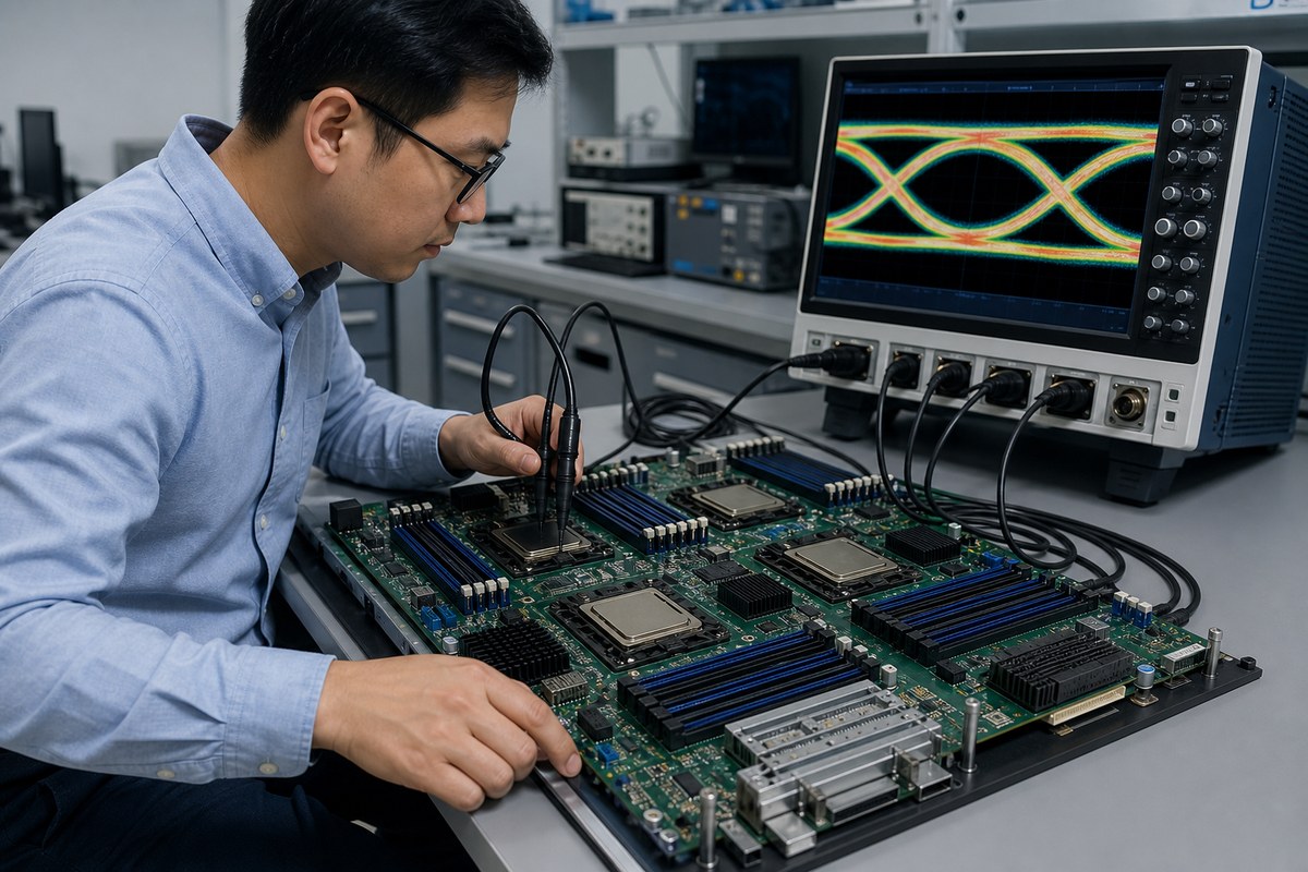
Our guides to stripline versus microstrip routing and eye diagram signal integrity explain two parts of this verification path.

Engineer measuring signal integrity on an AI server PCB with an oscilloscope eye diagram

How Should Power Integrity Be Designed?

Power integrity should keep every critical rail within its allowed voltage window during steady-state and transient operation. The work begins with target impedance and current-step assumptions, then connects regulator placement, plane geometry, decoupling, vias, and measurement access.
Place high-frequency decoupling close to the package power pins through short, low-inductance connections. Use appropriate plane areas and via arrays for current flow, but check the thermal and fabrication consequences of heavy copper concentration. Simulate the PDN over the relevant frequency range and reserve probe access for board-level correlation.

How Should Thermal and Mechanical Constraints Be Coordinated?

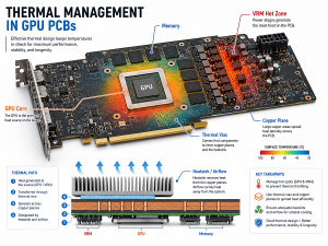
Thermal and mechanical decisions must be included before placement is frozen because cooling hardware, board stiffness, package warpage, and connector loading can change the electrical layout. A thermally attractive component location may be poor if it lengthens critical channels or blocks power entry.

  • Coordinate heatsinks, cold plates, airflow, mounting hardware, and keep-outs with placement.
  • Review copper balance, board thickness, panel support, and assembly thermal mass.
  • Protect press-fit zones, edge connectors, and large packages from excessive board flex.
  • Place temperature sensors and validation points where they measure meaningful conditions.
  • Define operating and qualification profiles before selecting materials and assembly cycles.

Which Via Structures Work for Accelerator Escape Routing?

The via structure should solve BGA escape and transition performance without creating an unnecessarily complex build. Through vias remain useful where density and channel performance allow them; blind, buried, and laser-drilled microvias are selected when routing density or stub control requires them.

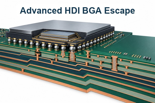
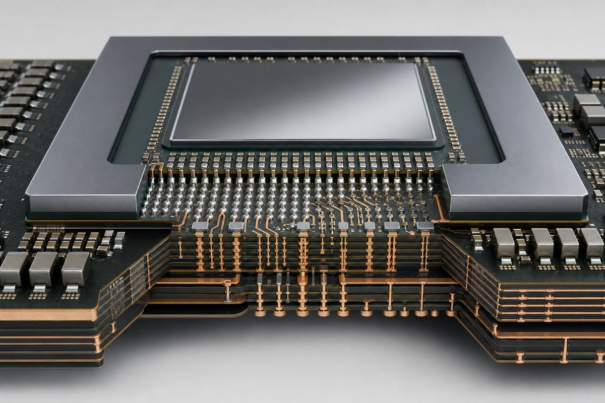
For an AI accelerator PCB or GPU PCB design, review pad size, capture pad, antipad, aspect ratio, stacked or staggered construction, copper filling, planarization, sequential lamination, and inspection access together. Our microvia aspect ratio guide explains why geometry must be confirmed before release.

AI accelerator BGA escape routing with via-in-pad microvias and multilayer power planes

How Does AI Server PCBA Affect the Layout?

AI server PCBA requirements affect pad design, component spacing, thermal profiling, inspection access, rework strategy, and panel support. Dense BGA packages, heavy copper areas, large connectors, and mixed thermal masses make assembly feedback necessary before the board is finished.

Confirm the package land patterns and paste strategy against component data. Provide access for AOI, X-ray, boundary scan, programming, and functional test where applicable. If a critical BGA cannot be visually inspected, define the X-ray acceptance and process-control approach before production.

What Should Be Verified Before Prototype Release?

Prototype release should occur only after the electrical intent and manufacturing package agree. A file-count checklist is not enough; the review must find contradictions between files and assumptions.

  1. Confirm the board role, interface list, channel boundaries, power rails, and acceptance owners.
  2. Reconcile the stackup, impedance table, routing rules, material model, and total thickness.
  3. Compare every via depth pair and backdrill definition with the actual layer map.
  4. Review SI, PI, thermal, and mechanical assumptions against the released layout revision.
  5. Check Gerber, ODB++ or IPC-2581 data, drill files, fabrication notes, BOM, and placement data for revision consistency.
  6. Define coupons, measurements, test conditions, sample quantities, and pass/fail ownership.
  7. Record approved deviations and decide which changes require re-simulation or requalification.

Use the final URL for this AI server PCB design guide in project documentation so design, manufacturing, and validation teams reference the same release checklist.

FAQ About AI Server PCB Design

How many layers does an AI server PCB need?

There is no fixed layer count. The required stackup follows routing density, reference-plane needs, power distribution, board thickness, connector constraints, and the chosen via architecture. Select the layer count after preliminary placement, escape analysis, channel planning, and fabricator review.

Does every AI server PCB require HDI?

No. HDI is used when package escape, routing density, or transition performance cannot be achieved efficiently with conventional structures. Some support or power boards may not need microvias, while accelerator and dense compute boards often require more advanced interconnects.

Can standard FR-4 be used for AI server PCB design?

It may be suitable for slower support circuits or short channels, but critical high-speed links need a material decision based on the channel loss budget and construction. Do not approve a material from its generic family name alone.

Why is copper roughness important?

Copper surface profile contributes to conductor loss at high frequencies. The simulation model and fabrication specification should use compatible roughness assumptions, especially on long or margin-sensitive channels.

When is backdrilling required?

Backdrilling is considered when unused plated-through-hole stubs consume too much channel margin. The need and residual-stub target should come from transition modeling and must be translated into an unambiguous controlled-depth drill definition.

What is the most important PDN input?

The PDN needs credible rail tolerances, current demand, and transient assumptions. Without them, a target-impedance result may look precise but cannot prove that the processor or accelerator stays within its allowed voltage window.

How early should the PCB manufacturer review the stackup?

Review should start before routing rules and via structures are frozen. Early feedback can align available materials, finished dielectric thicknesses, copper weights, drill structures, and impedance geometries with the design model.

What test structures should be planned?

Plan structures that support the actual acceptance method, such as impedance coupons, loss or correlation structures, power test points, and assembly inspection access. Their design and location should be agreed before panelization.

What files should accompany an AI server PCB RFQ?

Provide the fabrication data, stackup, drill and backdrill definitions, impedance requirements, material assumptions, fabrication drawing, quantities, and revision. For assembly, add the BOM, centroid data, assembly drawings, test requirements, and any programming files.

How can prototype results be carried into mass production?

Keep the material construction, drill structure, process notes, test method, and acceptance evidence under revision control. If a production change alters an electrical or mechanical assumption, route it through the same owners who approved the prototype baseline.

How Can EBest Circuit Support Your AI Server PCB Project?

At EBest Circuit, we support PCB design, prototyping, fabrication, component sourcing, and PCB assembly from the same controlled data package. Our engineering review can help identify conflicts among the stackup, impedance requirements, drill structure, materials, assembly constraints, and released files before the order moves forward.

Send your Gerber or ODB++ data, stackup, drill files, impedance targets, BOM, quantities, and test requirements to sales@bestpcbs.com. Our engineering team can review the package and confirm the applicable manufacturing path for your project.

You may also like