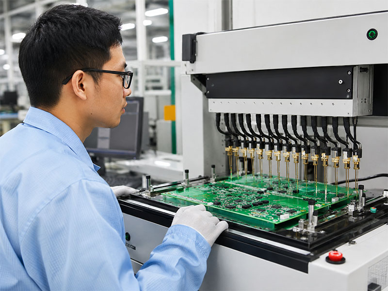
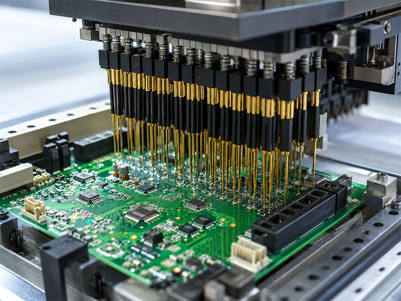
Extra thin PCB refers to a printed circuit board with a significantly reduced thickness compared to standard FR4 boards, enabling compact, lightweight, and space-constrained electronic designs.
As modern devices become smaller and more integrated, ultra thin PCB solutions are increasingly used in smart cards, wearable devices, and miniature modules where every micron matters.
Are You Facing These Challenges?
Many customers come to us with similar design concerns:
The product housing leaves very little board space
Standard PCB thickness is too bulky for the assembly
Flexible PCB is not necessary, but standard rigid PCB is too thick
Thin boards may warp or become hard to handle in production
Small electronic modules need a lighter and slimmer rigid solution
Our extra thin PCB service is built to solve these issues with practical FR4-based manufacturing support.
What Is an Extra Thin PCB?
An extra thin PCB is a rigid printed circuit board with a thickness significantly lower than a normal FR4 board. Standard PCB thickness is usually around 1.0 mm to 2.0 mm. In thinner conventional constructions, 1-layer or 2-layer boards may be made at 0.3 mm to 0.4 mm, while 4-layer boards are often around 0.6 mm.
When electronic products require an even slimmer profile, designers may specify thicknesses such as 0.25 mm, 0.20 mm, or 0.15 mm. These ultra-slim boards are commonly referred to as extra thin PCB, ultra thin PCB, or very thin PCB.
They are especially useful in products where every fraction of a millimeter affects housing design, connector fit, weight, or assembly clearance.
As consumer and industrial devices continue moving toward lighter and more compact designs, extra thin PCBs are becoming more widely used. They help optimize the internal layout without forcing a full shift to flexible circuits.
Key benefits include:
Reduced product thickness
Lower overall weight
Better fit for compact assemblies
More rigid than flexible circuits
More cost-effective than FPC in many simple designs
Suitable for slim modules with limited installation space
In some applications, extra thin FR4 PCB can also provide slight bendability during assembly. It does not replace a true flex circuit, but it can offer more mechanical tolerance than a standard rigid board.
Extra Thin PCB Applications
Extra thin PCBs are commonly used in products that demand a slim form factor and stable board structure. Typical applications include:
SIM card modules
TF card modules
NFC devices
Mobile phone charging modules
Wearable electronics
Drawing tablets
Metro coins or smart token devices
These products often have very limited internal clearance, making thin board construction an important part of the mechanical design.
Extra Thin PCB Manufacturing Capability
EBest Circuit provides extra thin PCB fabrication with the following capability range:
Item
Capability
Base Material
FR4 Tg130, Tg170, Tg180
Board Thickness
0.10 mm to 0.30 mm
Copper Thickness
0.5 oz, 1 oz, 2 oz, 3 oz
Outline Processing
Routing, punching, V-cut, laser cutting
Solder Mask
Bare, white, black, blue, green, red
Silkscreen Color
Black, white
Surface Finish
Immersion gold, OSP, ENEPIG, HAL-LF
Max Panel Size
500 Ć 500 mm or 1000 Ć 350 mm
Min Panel Size
3.5 Ć 3.5 mm
Min Single Size
25 Ć 25 mm
Min Via Size
0.10 mm
Min Trace / Space
4/4 mil
Packing
Vacuum packing
Sample Lead Time
7 to 9 days
Mass Production Lead Time
8 to 10 days
We can manufacture extra thin boards with or without solder mask, depending on the design and end-use requirement.
Extra Thin PCB vs Flexible PCB
Although they may look similar in ultra-slim products, extra thin PCB and flexible PCB serve different purposes.
Extra Thin PCB
FR4-based rigid board
Better structural support
Easier for handling and assembly
Usually lower cost than FPC in comparable simple layouts
Suitable when slight thinness is needed, but repeated bending is not required
Flexible PCB
Built on polyimide or other flexible materials
Designed for dynamic bending or folding
Better choice for extremely thin or moving interconnect structures
Suitable when board thickness must go below 0.10 mm or when repeated flexing is required
If your design needs a board below 0.10 mm, a flex circuit is generally the better option. If you need a thin, stable, and economical rigid board, extra thin FR4 PCB is often the more practical solution.
Stack-Up of Extra Thin PCB
The construction of extra thin PCB is similar to standard FR4 PCB, but the material system is thinner and the process window is tighter. The board uses thinner core materials and prepregs to achieve the required final thickness.
Because the structure is much thinner, stack-up design becomes more sensitive. Material choice, copper balance, and lamination control all affect flatness, handling strength, and final dimensional stability.
For 2-layer to 4-layer extra thin PCBs, the stack-up is usually simpler than conventional multilayer boards, but it must still be engineered carefully to maintain production consistency.
2L PCB structure for extra thin PCB
4L PCB structure for extra thin PCB
How Are Extra Thin PCBs Manufactured?
The basic fabrication flow is close to standard FR4 PCB manufacturing, but extra thin boards require tighter control at every stage. Thin materials are easier to deform during drilling, imaging, etching, lamination, routing, and transportation through the production line.
To support reliable production, EBest Circuit uses stricter handling methods and more precise process control for extra thin boards. In some operations, dedicated equipment or supporting fixtures are used to improve stability and reduce the risk of deformation or damage.
This is especially important for:
Panel handling
Warpage control
Fine drilling accuracy
Outline precision
Surface protection
Final packing and shipment stability
Careful process control helps ensure that the finished boards meet both dimensional and reliability requirements.
Why Choose EBest Circuit for Extra Thin PCB?
Choosing the right supplier for extra thin PCB is not only about whether thin boards can be produced. It is also about whether the manufacturer can keep those boards stable, consistent, and practical for real assembly conditions.
At EBest Circuit, we provide:
Extra thin FR4 PCB fabrication for compact designs
Thickness options from 0.10 mm to 0.30 mm
Multiple copper weights and surface finishes
Prototype and volume production support
Engineering review before production
Stable manufacturing control for delicate thin boards
Fast lead times for samples and mass production
We understand the common manufacturing risks behind ultra-thin rigid boards and work to reduce handling issues before they become assembly problems.
Work with a Reliable Extra Thin PCB Manufacturer | EBest Circuit
If your project requires a thinner rigid board for compact electronics, EBest Circuit can help you move from design to production with stable manufacturing support.
We offer extra thin PCB solutions for card devices, wearable products, NFC modules, charging applications, and other slim electronic assemblies. Whether you need a prototype or volume production, our team can support your design with suitable materials, practical fabrication control, and responsive engineering service.
Looking for a dependable extra thin PCB manufacturer? Contact EBest Circuit today to discuss your project and request a quote.
FAQs About Extra Thin PCB
1. What is the thinnest PCB you can manufacture?
We can produce extra thin PCBs down to 0.10 mm using FR4 materials. For thinner requirements, flexible PCB is recommended.
2. Can extra thin PCB replace flexible PCB?
No. Extra thin PCB offers slight bendability but is not designed for dynamic flexing. For bending applications, FPC is required.
3. Is ultra thin PCB more expensive?
It is slightly higher than standard PCB due to tighter process control, but still more cost-effective than flexible PCB.
4. What copper thickness is supported?
We support 0.5 oz, 1 oz, 2 oz, and 3 oz depending on current and design requirements.
5. How do you prevent warpage in thin PCB?
We use optimized lamination parameters, panel support fixtures, and controlled handling processes to ensure flatness.
6. What industries use extra thin PCB the most?
Smart cards, wearable devices, consumer electronics, and compact modules are the most common applications.
Need Ultra Thin PCB for Your Project?
If your design requires a compact, lightweight, and reliable PCB solution, extra thin PCB is a practical choice.
EBest Circuit (Best Technology) brings nearly 20 years of PCB manufacturing experience to high-current and power distribution projects. We provide one-stop support for bus bar PCB solutions, covering layout review, engineering evaluation, prototyping, mass production, and after-sales service.
Our manufacturing system is backed by ISO9001, ISO13485, IATF16949, and UL certifications, helping customers build reliable products for demanding industries. Whether you need a custom embedded bus bar PCB, copper inlay PCB, or extruded copper PCB, our team can tailor the structure to your current, thermal, and mechanical requirements.
What is Bus Bar PCB?
A bus bar PCB, also known as an embedded bus bar, busbar PCB, extruded copper PCB, or copper inlay PCB, is a specialized type of heavy copper PCB designed specifically to distribute power efficiently across different components on a board. Unlike traditional PCBs, which use copper traces etched into layers of non-conductive substrate to form circuits, bus bar PCBs integrate thick, solid bars of conductive materialāoften copper or aluminumāto handle higher currents.
The bus bar PCBs can also serve as mechanical connectors within the system, designed to accommodate screws and other metal parts for direct connections with other PCBs or system components.
Advantages of Bus Bar PCB
The PCB stiffener busbars can increase the rigidity and strength of circuit boards, so they can be used in severe environments like automotives, military instruments, aerospace, etc.
Higher power distribution and current-carry capabilities for power supply circuits or high-power applications.
The low voltage drop characteristic allows all components to maintain stable power delivery, especially under high load conditions.
The conductive bars inĀ bus bar PCBs acts as an effective heat sink, helping to dissipate heat more efficiently than standard fiberglass PCBs, avoiding overheating problems during use.
The ability to handle higher currents simplifies the design and assembly process without the need for multiple layout or complex traces.
Bus bar PCBsĀ can be used as electrical conduit, can also be used as mechanical connector.
They are often custom designed to meet specific application requirements, providing solutions that are not possible with standard PCB technology.
Basic Parameter of Bus Bar PCB Manufacturing
At EBest Circuit, bus bar PCB manufacturing can be customized according to current demand, installation method, and product structure. Typical capabilities include:
Minimum spacing between copper bars: 0.8ā1.0mm
Copper bar thickness: 1.0ā3.0mm
Current carrying capacity: 50ā300A
Copper bar forming: bars can be bent based on project requirements
Example: for 1.0mm copper, minimum hole size can be 0.7mm
Layer count: typically 3ā4 layers, with additional layers available after engineering review
Maximum dimension is 600*400mm for standardĀ bus bar PCB, 900*600mm for double sided PCB
The lead time of 3-4LĀ bus bar PCBĀ is around 13-15days, add 3days per layer over 4 layers.
These values may vary depending on the bus bar design, material selection, drilling limitations, and final assembly requirements.
Design Guide for Bus Bar PCB
Copper or aluminum is typically used for the bus bars due to their excellent conductivity and thermal properties. Copper is more conductive, while aluminum is lighter and offers better resistance to oxidation.
Choose substrates capable of handling high thermal loads and providing good electrical insulation. Common material we used is FR-4.
Determine the maximum current that each busbar needs to carry, so we can know the required cross-sectional area of the bus to minimize drag and heat buildup.
Use the length of the bus and the resistivity of the material to calculate the allowable voltage drop on the bus to ensure that it remains within an acceptable range.
Add mechanical mounting points to the bus, such as screw holes or connector slots.
Consider the mechanical stresses that the PCB may encounter, ensuring that the bus is flexible enough to withstand bending and strong enough to support structural loads.
Where Are Bus Bar PCBs Used?
Bus bar PCBs are used in products that require strong current handling, efficient heat control, and compact power routing. Common applications include:
Electric vehicles
Renewable energy systems
Industrial automation equipment
Power distribution units
Data center power systems
High-power spacecraft electronics
Consumer electronics with heavy current demand
Power inverters and converters
Aerospace and defense systems
In these fields, designers often need a solution that goes beyond standard heavy copper routing. Bus bar PCBs provide a practical way to combine power transmission, thermal performance, and mechanical integration in one board structure.
Need a Custom Bus Bar PCB?
If you are developing a high-current product and need a reliable bus bar PCB manufacturer, EBest Circuit can help. We support custom structures based on your current load, board dimensions, copper thickness, thermal requirements, and assembly needs.
Send us your drawings, Gerber files, or project requirements, and our team will review the design and provide a suitable manufacturing solution.
HDI PCB, or High Density Interconnect printed circuit board, is built for electronic products that demand more routing space, finer features, smaller vias, and higher circuit density in a limited footprint. Compared with conventional PCB structures, HDI boards support finer lines and spaces, smaller capture pads, and more interconnections per unit area, making them ideal for compact, lightweight, and high-speed devices.
At Best Technology, we provide standard HDI PCB, HDI flex PCB, 2ā16 layer HDI multilayer PCB, any-layer HDI PCB, rigid-flex PCB, and high-frequency PCB solutions for customers who need reliable performance, stable manufacturing, and fast turnaround. Our uploaded source also states a monthly production capacity of 260,000 square feet (28,900 square meters), with expedited service available for urgent projects.
What Is HDI PCB?
HDI PCB is the abbreviation of High Density Interconnect PCB. It is a printed circuit board designed with high integration, high precision, and miniaturized interconnection structures. HDI technology uses advanced processes such as microvia formation, via filling, and metallized interconnection to achieve reliable signal transmission and dense circuit routing.
In practical terms, HDI PCB helps designers place more functions into a smaller board area. This makes it a preferred solution for modern electronics that require smaller product size, lighter weight, faster data transfer, and improved electrical performance. The source material describes HDI boards as having finer lines and spaces below 100 μm, smaller vias below 150 μm, and smaller capture pads below 400 μm than conventional PCB technology.
Why Choose HDI PCB?
HDI PCB is widely used because it gives engineers more design freedom without sacrificing reliability.
Higher Circuit Density
HDI boards use tighter routing, smaller line width and spacing, and more advanced via structures. This allows more components and more functions to fit into the same board outline.
Better Signal Performance
Shorter signal paths and lower impedance help reduce signal delay and transmission loss. This is especially valuable in high-speed digital and high-frequency electronic applications.
Smaller and Lighter Product Design
HDI construction supports thinner, lighter, and more compact products. It is well suited to the ongoing trend toward portable and space-saving electronics.
Strong Reliability
With precise layer buildup, microvia structures, and better interlayer support, HDI boards can provide stable electrical performance and dependable mechanical structure in demanding assemblies.
Our HDI PCB Capabilities
We support a wide range of HDI PCB manufacturing solutions for both prototype and production requirements, including:
Item
Capability
Layer Count
2ā16 Layers (HDI), Any-Layer HDI Available
Min Line Width / Space
3/3 mil (HDI)
Min Via Size
~4 mil (Laser Microvia)
Via Type
Blind, Buried, Microvia, Via-in-Pad
Copper Thickness
0.5 oz ā 3 oz
Surface Finish
ENIG, ENEPIG, OSP, HASL, Immersion Silver
Board Thickness
0.2 mm ā 3.2 mm
BGA Capability
Down to 0.3ā0.4 mm pitch
Material Options
FR4, High-Tg, Low Dk/Df, Polyimide
Max Panel Size
Up to 1200 mm Ć 360 mm
Testing
AOI, X-Ray, Flying Probe, ICT
We also support fast-response manufacturing for urgent orders. According to the provided content, urgent boards can be shipped within 24 hours under suitable project conditions.
HDI PCB Types
According to layer up different, currently DHI board is divided into three basic types:
1) HDI PCB (1+N+1)
Features:
Suitable for BGA with lower I/O counts
Fine line, microvia and registration technologies capable of 0.4 mm ball pitch
Qualified material and surface treatment for Lead-free process
The substrate is the basis of HDI PCB. Commonly used organic insulating materials include thermosetting resins (such as phenolic resins and epoxy resins) and thermoplastic polyesters (such as polyimide and polytetrafluoroethylene). The choice of substrate depends on the needs of specific applications, such as rigid or flexible PCBs.
2. Copper foil
As a conductive material, the thickness of copper foil is generally between 0.3mil-3mil. The specific choice depends on the current carrying size and etching accuracy. The quality of copper foil directly affects the surface quality and electrical performance of the product.
3. PP (B-stage resin)
When making multi-layer PCBs, PP is an indispensable material as an interlayer adhesive.
4. Photosensitive materials
Including photoresists and photosensitive films, divided into wet films and dry films. These materials will undergo chemical changes under light of a specific wavelength, affecting their solubility in the developer, thereby achieving precise production of circuits.
5. Solder mask (ink)
As a solder mask, solder mask is used to prevent the adhesion of liquid solder, and its performance affects the welding quality and circuit protection of PCBs.
6. Film
Similar to the polyester film used for photography, the film is used to record image data and requires high contrast, sensitivity and resolution while ensuring fine lines and dimensional stability.
HDI PCB Manufacturing Process
The uploaded source outlines a typical HDI PCB manufacturing flow, covering the core steps from design to final inspection.
1. Design Review ā define the circuit structure, layer count, and stackup
2. Material Preparation ā prepare substrate, copper-clad material, covering layers, and inner layers
3. Laser Drilling ā create small vias for interlayer electrical connection
4. Lamination ā press the inner and outer layers into a stable structure
5. Etching ā remove excess copper and keep the required conductive pattern
6. Plating ā improve conductivity and oxidation resistance
7. Assembly ā insert and solder components if assembly service is included
8. Testing and Inspection ā verify quality and electrical performance
Typical Applications
HDI PCB is widely used in products that require compact design and high functional density. The original material lists applications such as:
Cell Phones
UMPC
PDA
GPS Devices
Memory Cards
Portable Game Consoles
Digital Cameras
Camcorders
Notebook Computers
Network Communication Equipment
Chip Carriers for Large-Scale IC Packaging
Why Work With EBest Circuit?
We position HDI PCB service around what engineering teams and sourcing teams actually need: broad process coverage, quick response, stable quality, and one-stop manufacturing support. The source content also highlights experience in high-end HDI, multilayer PCB, high-frequency PCB, high-speed PCB, FPC, rigid-flex PCB, SMT processing, and PCBA OEM service.
What You Can Expect
Wide HDI product range
Prototype to production support
Fast turnaround for urgent projects
One-stop PCB and PCBA service
Competitive pricing with manufacturing support
FAQs About HDI PCB
1. What is the difference between HDI PCB and standard PCB?
HDI PCB uses finer lines, smaller vias, and higher connection density, allowing more circuits in less space compared to standard PCB.
2. When should I use HDI PCB?
HDI is recommended when your design includes fine-pitch BGA, high-speed signals, or strict space constraints.
3. Is HDI PCB more expensive?
Yes, due to more complex processes and tighter tolerances. However, it can reduce overall system size and improve performance.
4. What is the minimum via size in HDI PCB?
Typically around 4 mil (laser drilled microvia), depending on manufacturer capability.
5. Can HDI PCB improve signal integrity?
Yes. Shorter routing paths and better layer control can improve signal performance in high-speed designs.
6. How long does HDI PCB manufacturing take?
Prototype lead time can be as fast as 24 hours, while standard production depends on complexity and volume.
Get a Quote for Your HDI PCB Project
If your project requires microvias, fine-pitch BGA routing, higher wiring density, or compact multilayer construction, HDI PCB may be the right solution. A well-designed HDI board can help reduce product size, improve routing efficiency, and support stronger electrical performance in advanced electronics.
Send us your Gerber files, stackup requirements, and project specifications. Our team can review your design and recommend a suitable HDI PCB manufacturing solution.
How to solve overheating, component failure and reliability issues in automotive battery management systems and ensure efficient BMS operation in harsh vehicle environments? High-qualityautomotive BMS MCPCB provides the solution. It delivers the thermal conductivity, structural stability and electrical isolation critical to BMS performance. This blog covers key design considerations, real-world applications, common challenges and solutions for automotive BMS MCPCB. It also explains why EBest is the top choice for your automotive BMS MCPCB needs, whether you need thermal management optimization, long-term reliability or a trusted supplier.
Why Choose EBest for Your Automotive BMS MCPCB Manufacturer?
EBest delivers automotive-grade automotive BMS MCPCB solutions tailored to your needs. We combine proven expertise, strict quality control and reliable support to ensure your BMS projects run smoothly, with no delays or compromises on performance.
Superior Quality & Compliance: Our automotive BMS MCPCB meets IATF 16949 and other automotive standards, with full material traceability and rigorous testing to ensure consistency and reliability.
Optimized Thermal Performance: Built with high-quality materials to deliver 1ā10 W/mĀ·K thermal conductivity, our boards effectively dissipate BMS heat, preventing component failure and extending service life.
Flexible Customization: We offer tailored designs for automotive BMS MCPCB, adjusting thickness, copper weight and surface finishes to match your specific BMS application needs.
Reliable Lead Times: Fast prototyping (7ā10 days) and stable mass production scheduling keep your projects on track, avoiding costly delays.
Expert Support: Our team provides dedicated engineering assistance for DFM and thermal optimization, ensuring your BMS design is efficient and manufacturable.
Stable Supply Chain: Verified material sources and consistent production capacity guarantee steady supply, even for large-scale orders.
EBest’s Certifications for Automotive BMS MCPCB: Proof of Quality and Compliance
Our commitment to quality is backed by industry-leading certifications, ensuring ourautomotive BMS MCPCB meets global automotive standards:
IATF 16949: Automotive-specific quality standard, ensuring our automotive BMS MCPCB meets OEM requirements and adheres to strict automotive industry quality control processes.
ISO 9001:2015: The international standard for quality management systems, providing a framework to ensure consistent, high-quality production of our automotive BMS MCPCB and continual improvement of our processes.
ISO 13485:2016: Medical device quality management system standard, ensuring our automotive BMS MCPCB meets the high-reliability requirements for medical-related automotive applications.
AS9100D: Aerospace quality management system standard, guaranteeing our automotive BMS MCPCB meets the rigorous reliability and performance standards required for aerospace and high-end automotive applications.
REACH: EU chemical compliance standard, ensuring our automotive BMS MCPCB is free from restricted chemicals and safe for global markets.
RoHS: Compliance with restrictions on hazardous substances, meeting global environmental standards and ensuring our automotive BMS MCPCB is eco-friendly.
UL: Safety and flammability compliance standard, critical for automotive electrical systems and ensuring our automotive BMS MCPCB meets strict safety requirements.
Common Pain Points of Automotive BMS MCPCB: How EBest Solves Your BMS Challenges
Automotive BMS performance issues often stem from inadequate thermal management, poor durability and subpar component reliability. These challenges can lead to costly delays, reduced battery life and safety risks. Below are the most common pain points teams face with automotive BMS MCPCB, along with practical solutions from EBest to resolve them.
Excess Heat Buildup: MOSFETs, shunts and ICs in BMS generate significant heat during operation. This heat reduces efficiency and leads to premature component failure, a critical issue since 38% of battery failures in electric vehicles trace back to BMS malfunctions. Our automotive BMS MCPCB offers 3ā5x better thermal conductivity than standard PCBs, rapidly dissipating heat to keep components cool and prevent performance drops.
Weak Thermal Dissipation with FR4: Traditional FR4 PCBs have low thermal conductivity (0.3ā0.5 W/mĀ·K), making them unable to handle high currents and heat in modern BMS designs. This increases the risk of thermal runaway, especially when temperatures exceed 60°C. Our automotive BMS MCPCB uses thermally enhanced metal cores to replace FR4, preventing thermal runaway and extending BMS service life.
Temperature Imbalance: Uneven heat distribution across BMS modules shortens battery cycle life and raises failure risks. Even small temperature inconsistencies can reduce battery lifespan by 20ā30% over time. Our automotive BMS MCPCB ensures uniform heat dissipation, balancing temperatures across the entire module to protect battery health.
Mechanical Instability: Vibration and humidity in vehicle environments weaken standard PCBs, leading to structural damage and connection failures. Commercial vehicles face a 30% failure rate due to poor vibration resistance. Our automotive BMS MCPCB uses durable aluminum cores to withstand harsh automotive conditions, ensuring long-term mechanical stability and reliability.
Inconsistent Quality & Traceability: Many low-quality MCPCBs lack material traceability and fail to meet automotive standards, leading to batch inconsistencies and compliance issues. EBestās automotive BMS MCPCB comes with full material traceability and rigorous testing, ensuring consistent quality and adherence to global automotive standards.
EBest’s automotive BMS MCPCB is engineered to address these core pain points comprehensively. Our solutions combine thermal efficiency, mechanical durability and strict quality control to ensure your BMS operates reliably. Choose EBest for automotive BMS MCPCB that solves your challenges and keeps your projects on track.
What Is an Automotive BMS MCPCB?
An automotive BMS MCPCB (Metal Core Printed Circuit Board) is a specialized, thermally enhanced circuit board made specifically for vehicle battery management systems. It differs from standard PCBs by using a metal base, usually aluminum, to address the unique heat challenges of BMS applications.
A thin dielectric layer sits between the metal base and the circuit layer. This layer keeps the circuit electrically isolated while letting heat transfer efficiently from the board to the metal core. This design is critical for BMS performance. It pulls heat away from high-power components like MOSFETs and shunts, preventing overheating that can damage parts or reduce battery life.
Automotive BMS MCPCB is built to handle the high currents and extreme temperature swings of vehicle environments. It ensures reliable BMS operation, which is essential for electric and hybrid vehicle performance and safety.
Why Use MCPCB Instead of FR4 for BMS?
Metric
Automotive BMS MCPCB
FR4 PCB
Thermal Conductivity (Critical for BMS Heat Dissipation)
1ā10 W/mĀ·K, efficiently dissipates heat from MOSFETs, shunts and ICs to prevent overheating.
0.3ā0.5 W/mĀ·K, too low to handle high-power BMS heat, leading to component overheating.
BMS Component Reliability
Prevents thermal runaway and premature component failure, extending BMS service life significantly.
High risk of component damage due to poor heat dissipation, shortening BMS lifespan.
Ability to Handle High Currents
Designed for high-current BMS charging/discharging paths, supports 48V, 400V and 800V BMS designs.
Struggles with modern high-current BMS applications, prone to performance drops or failure.
Mechanical Stability (Automotive Environment)
Rigid metal core (aluminum) resists vibration, humidity and thermal cycling in vehicle environments.
Fiberglass base is fragile, prone to warpage and solder joint failure under automotive vibration.
Battery Life Impact
Balances module temperatures, prevents thermal degradation and extends battery cycle life by 20ā30%.
Temperature imbalance shortens battery life, increasing long-term replacement costs.
Automotive Compliance
Meets IATF 16949 and other automotive standards, suitable for OEM BMS applications.
Not optimized for automotive standards, may fail compliance checks for vehicle use.
Design Flexibility
Customizable thickness, copper weight and surface finishes to match specific BMS design needs.
Limited customization, not adaptable to high-performance BMS requirements.
How Does Thermal Conductivity Affect BMS Performance?
Thermal conductivity is the most critical parameter for automotive BMS MCPCB, directly impacting how well your BMS operates. It measures how quickly heat moves through the board, and higher conductivity means better heat dissipation.ā For automotive BMS, thermal conductivity requirements vary by application:ā
1ā2 W/mĀ·K: Ideal for low-power BMS sections, such as monitoring circuits.ā
3ā4 W/mĀ·K: Perfect for mid-power BMS modules, balancing performance and cost.ā
5ā10 W/mĀ·K: Essential for high-current charging and discharge paths, where heat generation is highest.ā
Higher thermal conductivity in automotive BMS MCPCB means lower component temperatures, better BMS stability, and longer battery life.
What Materials Are Used in Automotive BMS MCPCB?
EBest uses controlled, traceable materials for automotive BMS MCPCB:
Base Material: EBest uses Aluminum 5052 or 6061 for the core of automotive BMS MCPCB. These aluminum alloys provide excellent thermal conductivity and strong mechanical strength, making them suitable for automotive environments with vibration, humidity and extreme temperature changes.
Dielectric Layer: The dielectric layer is made of thermally conductive ceramic filled polymer. It maintains electrical isolation between the circuit and metal base while enabling efficient heat transfer from the circuit layer to the metal core for quick dissipation. This material can achieve high dielectric constants by filling ceramic powders like BaTiO3, enhancing overall performance.
Circuit Layer: The circuit layer adopts 1ā6 oz rolled annealed copper to ensure reliable current handling for all BMS circuit needs. Thicker copper options are available for high current BMS applications to maintain stable performance and avoid overheating.
Surface Finish: EBest offers three high performance surface finishes HASL, ENIG and Immersion Silver. All options provide superior solderability and corrosion resistance to ensure strong and durable component connections for automotive BMS. HASL is ideal for high power components while Immersion Silver fits high reliability scenarios.
All materials used in EBest automotive BMS MCPCB are high quality and fully traceable. They are carefully selected to meet the harsh demands of automotive environments and ensure consistent performance and long term reliability for your BMS projects.
What Are the Key Design Rules for Automotive BMS MCPCB?
Designing an automotive BMS MCPCB requires careful attention to thermal management and component placement. Follow these key rules to ensure your BMS design is efficient and reliable:
Maximize copper area under power components like MOSFETs and shunts to improve heat dissipation. Larger copper areas increase heat transfer efficiency, reducing component temperatures by 15ā25% and lowering the risk of thermal fatigue, which is critical for high-power BMS operation.
Place hot components away from sensitive ICs to prevent thermal interference and damage. Sensitive BMS ICs (such as voltage monitoring chips) have strict operating temperature limits (typically 0ā85°C), and placing them near hot components can cause measurement errors or premature failure.
Use thermal vias and thermal pads to transfer heat from the circuit layer to the metal core of the automotive BMS MCPCB. Thermal vias (arranged in a grid pattern) enhance heat transfer by 30ā40% compared to standard vias, ensuring heat is quickly dissipated to the aluminum core and away from critical components.
Maintain proper dielectric isolation for high-voltage BMS applications, following automotive safety standards. For 400V+ BMS designs, the dielectric layer thickness should be at least 100μm to prevent electrical breakdown, while 800V systems require thicker dielectric layers to meet isolation requirements.
Adhere to creepage and clearance requirements to prevent electrical arcing and ensure BMS safety. For 800V BMS systems, follow GB/T 18384.3 standards: high-voltage line spacing should be ā„8mm, and line-to-ground spacing ā„6mm; add 10% redundancy to offset production etching deviations (line width tolerance ±0.03mm).
Match copper weight to BMS current requirements to avoid voltage drop and overheating. For low-current monitoring circuits, 1ā2 oz copper is sufficient; high-current charging/discharging paths require 4ā6 oz copper to handle currents up to 100A without performance loss.
Use rounded corners for high-voltage traces and copper pads instead of right angles. Right-angle traces create electric field concentration, increasing the risk of arcing in harsh automotive environments; rounded corners (radius ā„1mm) reduce this risk and improve overall board reliability.
Separate analog and digital circuits on the MCPCB to minimize electromagnetic interference (EMI). BMS voltage monitoring (analog) and control signals (digital) are susceptible to EMI, which can cause data inaccuracies; separating these circuits with a ground plane reduces interference and ensures stable BMS operation.
Incorporate a solid ground plane connected to the MCPCBās metal core to enhance EMI shielding and heat dissipation. The ground plane acts as a shield against external interference and provides an additional heat dissipation path, further protecting sensitive BMS components.
Avoid unnecessary cutouts in the MCPCB metal core. Cutouts disrupt heat distribution and reduce mechanical stability, making the board more prone to warpage under automotive thermal cycling; only use cutouts when required for component fit or assembly.
How to Ensure Reliability in Automotive BMS MCPCB?
Reliability is critical for automotive BMS as failures cause battery damage safety risks and downtime. A 2026 study shows 45% of automotive electronic failures stem from thermal cycling and 30% from vibration requiring strict quality control. Below are practical steps to ensure automotive BMS MCPCB reliability:
Demand Full Material Traceability and Compliance Certificates: Request COC for all MCPCB materials to meet automotive grade standards. EBest provides full traceability and documentation to meet IATF 16949 and OEM requirements avoiding subpar performance.
Implement Strict Thermal Cycling and Thermal Shock Testing: Automotive BMS MCPCB must withstand -40ā to 125ā. Follow AEC Q100 Rev H conduct 1500 cycles of -40ā 30min to 125ā 30min to simulate 10 years of use and verify resistance to delamination and solder joint cracking.
Conduct Comprehensive Electrical Integrity Testing: Perform open short circuit and Hi Pot tests. For 400V plus BMS use 1500V DC for 60 seconds to verify dielectric integrity and prevent arcing or short circuits.
Verify Solderability and Component Adhesion: Test solder joint strength to meet IPC 6012 Class 3. EBest uses vacuum reflow soldering oxygen content less than 100ppm to keep solder void rate below 5% for strong component bonds.
Test for Vibration and Humidity Resistance: Follow ISO 16750 3 conduct 32 hours of random vibration and 50g impact tests. Perform 10 cycles of salt fog damp heat and drying to prevent corrosion.
Inspect for Manufacturing Defects with X Ray and Visual Testing: Use X Ray to detect hidden defects and visual inspection per IPC A 600 to check for damage reducing defect rates by up to 70%.
Validate Long Term Durability with Accelerated Aging Tests: Conduct 1000 hours of 85ā/85% RH damp heat testing. EBest’s MCPCB maintains less than 10% electrical performance change ensuring long term reliability.
EBest automotive BMS MCPCB undergoes all these quality control steps ensuring high reliability for harsh automotive environments.
Real Automotive BMS MCPCB Application Examples
Real Automotive BMS MCPCB Application Examples: Solving Real-World BMS Problems
48V Mild Hybrid BMS
Board: 3.0 W/mĀ·K automotive BMS MCPCB
Function: MOSFET and current shunt monitoring for hybrid vehicle BMS.
Solution: Reduces MOSFET temperature by 28°C, improving BMS efficiency and preventing overheating. This ensures the hybrid system operates smoothly, reducing fuel consumption and emissions.
Function: Charge and discharge power regulation for electric vehicle main batteries.
Solution: Balances cell temperature across the battery pack, extending battery cycle life and improving charging efficiency. This helps EVs achieve longer range and more reliable performance.
BMS Protection & Balancing Board
Board: 2.0 W/mĀ·K automotive BMS MCPCB
Function: Passive cell balancing for automotive BMS, ensuring even charge distribution.
Solution: Lowers balancing resistor heat and prevents hotspots, reducing the risk of component failure and extending BMS life.
How to Optimize DFM for Automotive BMS MCPCB?
Design for manufacturability (DFM) is key to reducing costs, improving yield and speeding up production of automotive BMS MCPCB. Follow these practical, easy-to-follow tips to optimize your DFM:
Simplify the layer structure (preferably 1ā2 layers for standard BMS modules) and avoid unnecessary cutouts. This reduces production complexity, material waste and errors, while aligning with IPC-6012 Class 3 guidelines.ā
Standardize thermal pad sizes to 5mmĆ5mm or 10mmĆ10mm to match common BMS component footprints. Non-standard sizes increase solder voids and costs, while standardization improves yield and compatibility with automated assembly.ā
Minimize small, dense features. Follow IPC-2221 standards (minimum 0.15mm trace width for automotive BMS) to reduce etching errors and avoid costly specialized production processes.ā
Use surface finishes compatible with your BMS components. EBest recommends HASL for high-power components (MOSFETs, shunts) and ENIG for sensitive ICs to prevent solder joint cracking and ensure reliability.ā
Align designs with standard production capabilities. Use 1.0mm (low-power BMS) or 1.6mm (high-power BMS) base thicknesses to avoid lead time delays and cost overruns from custom sizes.ā
Optimize copper weight to match BMS current needs. Follow the 1oz copper per 30A rule to avoid over-engineering, reduce material costs and speed up etching processes.ā
Design uniform solder mask openings, standardizing to 0.1mm larger than the pad size. This ensures consistent solder application and aligns with automated stencil printing.ā
Avoid tight tolerances unless critical. A ±0.03mm tolerance is sufficient for most automotive BMS applications, reducing costs from specialized equipment and maintaining performance.ā
Place test points along board edges (at least 2mm from edges) for easy access. This simplifies quality inspection, improves efficiency and reduces the risk of missed defects.ā
Collaborate with your MCPCB supplier early in the design phase. Early collaboration reduces DFM-related redesigns by 60% and shortens lead times, with EBest offering free DFM reviews to identify issues upfront.
What Testing Standards Apply to Automotive BMS MCPCB?
Automotive BMS MCPCB must meet strict testing standards to ensure reliability and safety. The most important standards for automotive BMS MCPCB include:
IPC-6012 Class 3: Ensures high-reliability printed circuit boards, critical for automotive BMS.
IPC-A-600: Establishes acceptability criteria for printed circuit boards, ensuring quality.
IATF 16949: Automotive-specific quality management system, ensuring process control and compliance.
Thermal Impedance Testing: Measures the thermal performance of the automotive BMS MCPCB, ensuring it can dissipate heat effectively.
Hi-Pot & Isolation Voltage Test: Verifies electrical isolation, preventing arcing and ensuring safety.
Thermal Shock & Temperature Cycling: Tests the automotive BMS MCPCBās ability to withstand extreme temperature changes, a key requirement for automotive environments.
FAQs About Automotive BMS MCPCB
Q1: Are EBest BMS MCPCBs automotive-qualified? A1: Yes, all EBest automotive BMS MCPCB products are automotive-qualified. We manufacture our boards under the IATF 16949 standard, with full material traceability and rigorous testing to meet OEM requirements.
Q2: Can you customize thickness and copper weight for BMS MCPCB? A2: Yes, EBest offers full customization for automotive BMS MCPCB. We can adjust base thickness, copper weight, dielectric layer, and surface finish to meet your specific BMS design requirements.
Q3: Do you support 48V and 800V BMS designs? A3: Yes, EBest supports all common automotive BMS voltage platforms, including 12V, 48V, 400V, and 800V. Our automotive BMS MCPCB is designed to handle the unique thermal and electrical requirements of each voltage level.
Q4: What surface finishes are available for BMS MCPCB? A4: We offer a range of surface finishes for automotive BMS MCPCB, including HASL, ENIG, Immersion Silver, and ENEPIG. These finishes ensure strong solder joints and corrosion resistance, critical for automotive BMS reliability.
Q5: How does automotive BMS MCPCB improve battery life? A5: Automotive BMS MCPCB improves battery life by reducing heat buildup and balancing temperatures across the battery pack. By dissipating heat from BMS components, it prevents thermal degradation, extending the life of both the BMS and the battery
Automotive camera MCPCBā is a specialized metal-core printed circuit board designed to support high-performance imaging modules in vehicles by delivering superior thermal management and mechanical stability. This article explores how rigid-flex integration enhances compact vision systems, addresses common design and manufacturing challenges, and explains why choosing the right MCPCB partner matters for automotive applications.
Are you facing these common obstacles when developing automotive camera modules?ā
Overheating sensors causing image noise and failure
Limited space for routing and component placement
Poor signal quality due to EMI and impedance mismatch
Mechanical stress damaging rigid boards in moving parts
Inconsistent quality from unreliable PCB suppliers
As an experienced MCPCB manufacturer, EBest Circuit (Best Technology) provides targeted solutions to overcome these issues.ā
Metal core construction for efficient heat dissipation
Rigid-flex design enabling 3D folding and space savings
Controlled impedance and shielding for clean signals
Durable stack-ups resisting vibration and flexing
Strict process control ensuring consistent reliability
EBest Circuit (Best Technology) is a professional Automotive Camera MCPCB manufacturerā specializing in thermal management and rigid-flex integration for compact vision systems. With advanced production capabilities and automotive-grade quality standards, we deliver MCPCB For Automotive Camera Systemsā that meet stringent thermal, mechanical, and signal performance requirements. Pls feel free to contact us at sales@bestpcbs.com for custom solutions.
What Is Automotive Camera MCPCB?
An Automotive Camera MCPCB Moduleā integrates a metal-core substrate with precision circuitry to support image sensors, lenses, and processing components in vehicle vision applications. Unlike standard FR-4 boards, MCPCBs use aluminum or copper cores to rapidly transfer heat away from sensitive electronics.
Key characteristics include:
Metal Core Substrateā ā Aluminum or copper base for thermal conductivity
Dielectric Layerā ā Thin insulating material balancing heat transfer and electrical isolation
Circuit Layerā ā Copper traces for signal routing and power delivery
Surface Finishā ā ENIG or immersion silver for solderability and corrosion resistance
This structure makes Thermal MCPCB For Automotive Cameraā applications ideal for ADAS, surround-view, and night-vision systems where temperature control is critical.
Why Combine Automotive Camera MCPCB With Flex PCB In Compact Vision Modules?
Integrating Automotive Camera MCPCB With Flex PCB Integrationā creates a rigid-flex solution that solves space and reliability challenges in compact designs.
Feature
Rigid Section
Flex Section
Benefit
Structure
Metal core for heat dissipation
Polyimide for bending
Combines thermal + mechanical flexibility
Space
Supports components
Folds into tight spaces
Reduces module size by 30ā50%
Reliability
Stable mounting
Absorbs vibration
Improves durability in moving vehicles
Assembly
Standard SMT processes
Dynamic routing
Simplifies integration with vehicle harnesses
Rigid-flex designs allow cameras to fit into slim housings while maintaining thermal performanceāessential for modern compact vision systems.
When Should You Use Automotive Camera MCPCB In Vehicle Vision Systems?
Use Automotive Camera MCPCBā when your application requires:
High Thermal Loadsā ā Image sensors generating >2W of heat
Space Constraintsā ā Modules <20mm Ć 20mm footprint
Vibration Resistanceā ā Operation in engine bays or wheel wells
Signal Integrityā ā High-speed MIPI or LVDS interfaces
Automotive Certificationā ā AEC-Q100 or ISO 26262 compliance
These conditions are common in backup cameras, driver monitoring systems, and autonomous driving sensors.
What Materials Are Used In Automotive Camera MCPCB Thermal Stackups?
Material selection directly impacts thermal and electrical performance:
Layer
Common Materials
Key Properties
Metal Core
Aluminum 5052/6061, Copper
Thermal conductivity: 150ā400 W/mK
Dielectric
Thermally conductive epoxy, ceramic-filled
Breakdown voltage: >3kV, CTE matching
Circuit
1ā3oz copper
Low resistance, high current capacity
Coverlay
Polyimide, solder mask
Protection against moisture and chemicals
For Thermal MCPCB For Automotive Camera, aluminum cores are most common due to cost-effectiveness and sufficient thermal performance.
How To Optimize Automotive Camera MCPCB Layout For Better Thermal And Signal Performance?
Optimization strategies include:
Thermal Viasā ā Place under heat-generating components to conduct heat to metal core
Ground Planesā ā Continuous reference planes for signal integrity and EMI reduction
Rapid Prototypingā ā 5ā7 day turnaround for samples
Global Supportā ā Technical consultation and volume production
Pls feel free to contact sales@bestpcbs.com to discuss your automotive metal core PCB project requirements.
In summary, automotive camera MCPCBā enables compact, thermally efficient vision systems essential for modern vehicles through rigid-flex integration and advanced thermal management. This article covered design considerations, material selection, optimization techniques, and supplier evaluation criteria for successful implementation. EBest Circuit (Best Technology) provides industry-leading MCPCB For Automotive Camera Systemsā with proven reliability and technical support. Pls feel free to contact us at sales@bestpcbs.com to start your next automotive vision project.
FAQs About Automotive Camera MCPCB
Q: Can MCPCB handle high-resolution camera sensors?ā
A: Yes, with proper thermal design and controlled impedance layouts supporting MIPI CSI-2 interfaces up to 4K resolution.
Q: Whatās the minimum bend radius for flex sections?ā
A: Typically 10Ć the total thickness; we recommend 15Ć for automotive vibration environments.
Q: How does MCPCB compare to ceramic substrates?ā
A: MCPCB offers better cost-to-performance ratio for most automotive cameras, while ceramics excel in extreme thermal cycling.
Q: Are these boards waterproof?ā
A: The base MCPCB is not waterproof, but can be conformal coated or integrated into sealed modules.
Q: Whatās the typical lead time?ā
A: Prototypes: 5ā7 days; mass production: 2ā3 weeks depending on complexity.
Are you struggling with overheating, unstable light, or short lifespan when using standard PCBs for LED aquarium lights?LED aquarium light aluminum PCB solves these core issues with superior thermal management, waterproof structure, and stable performance to protect aquatic life and extend lighting life. For reliable, highāperformance LED Aquarium Light Aluminum PCB, EBest is your professional oneāstop supplier with mature design, production, and quality control capabilities. In this article, we explain key benefits, design points, applications, and FAQs to help you select and use the right PCB for your aquarium lighting projects.
Why Choose EBest as Your Supplier for LED Aquarium Light Aluminum PCB?
EBest delivers consistent quality, fast lead times, stable supply chain, and fullāservice support for LED aquarium light aluminum PCB.We focus on thermal performance, waterproof reliability, and longāterm durability required by aquarium lighting systems.Our core advantages include certified quality, flexible customization, and responsive technical support.
Quality Assurance: We follow strict international standards to ensure each PCB meets thermal, insulation, and waterproof requirements.Stable material selection avoids performance degradation in humid, highāheat aquarium environments.
Lead Time & Production Capacity: We support rapid prototyping and 24āhour expedited services for urgent projects.Our mass production capacity ensures stable delivery for largeāvolume orders.
Supply Chain & Cost Efficiency: Stable upstream material supply guarantees consistent batch quality.Optimized production flow improves efficiency while maintaining high performance.
FullāChain Service: We provide oneāstop solutions including design, prototyping, assembly, and mass production.Professional engineering support helps optimize your PCB layout and performance.
Customer Support: We offer personalized solutions and timely afterāsales service.Our team helps resolve design, assembly, and application issues quickly.
EBest’s Quality Certifications for LED Aquarium Light Aluminum PCB
Here are EBest’s quality certifications for LED aquarium light aluminum PCB:
ISO 9001:2015: International quality management system.
ISO 13485:2016: Medicalāgrade safety and stability.
AS9100D: Aerospaceāgrade precision and durability.
RoHS: Environmentally friendly, safe for aquatic life.
REACH: Chemical safety compliance.
UL: Safety and insulation certification.
What Common Problems Do LED Aquarium Light Aluminum PCB Users Face?
Here are common problems for LED aquarium light aluminum PCB:
Do you suffer from overheating that raises water temperature and stresses fish and corals?
Are you troubled by poor waterproofing that causes short circuits or PCB failure?
Do you experience spectrum shift and brightness decay due to uneven heat distribution?
Are you frustrated by short service life and high replacement frequency?
EBest’s LED Aquarium Light Aluminum PCB directly solves these problems.
High thermal conductivity quickly dissipates heat to stabilize water temperature.
Waterproof structure protects against moisture and splashes.
Stable thermal control maintains consistent light spectrum and brightness.
Rugged design extends service life and reduces maintenance.
Why Is LED Aquarium Light Aluminum PCB Essential for Aquatic Life?
Aquatic life is highly sensitive to water temperature and light stability. Even small temperature increases can stress fish, slow plant growth, or damage corals. Standard FR4 PCBs trap heat and gradually warm aquarium water.
LED aquarium light aluminum PCB provides excellent heat dissipation to keep temperatures safe.It maintains consistent light spectrum without shift or decay.This stable environment supports healthy growth for fish, coral, and aquatic plants.Using aluminum PCB significantly lowers risks of heatārelated damage to aquatic life.
How Does LED Aquarium Light Aluminum PCB Solve Overheating Issues?
Overheating is the biggest threat to LED aquarium lights and aquatic life.Highāpower LEDs generate large amounts of heat during longāhour operation. Traditional PCBs cannot transfer heat efficiently, leading to hotspots and rising water temperature.
LED aquarium light aluminum PCB uses a metal core substrate for fast heat conduction. It spreads heat evenly across the board instead of concentrating around LED chips. Lower thermal resistance reduces LED junction temperature effectively. Stable temperature extends LED lifespan and keeps water within safe ranges.
How to Design LED Aquarium Light Aluminum PCB for Waterproof Performance & Longevity?
Use waterproof, anti-yellowing, and anti-corrosion solder mask to block moisture and water splashes.
Adopt sealed edge treatment and full-board encapsulation to prevent water penetration into the substrate.
Optimize component layout to eliminate dead corners where water or condensation can accumulate.
Increase insulation thickness and reinforce dielectric design to avoid short circuits in humid environments.
Select high-thermal-conductivity aluminum base to reduce heat stress and material aging.
Use 1ā3 oz thick copper to improve current carrying capacity and ensure long-term working stability.
Avoid over-concentrated LED arrangement to prevent local overheating and speed up aging.
Add thermal relief design and uniform thermal paths to keep temperature stable and extend service life.
Comply with IP65 protection structure standards for reliable use in long-term humid aquarium environments.
Choose RoHS and REACH compliant materials to ensure safety and stability for aquatic life.
How Does LED Aquarium Light Aluminum PCB Balance Heat Dissipation & Spectrum Matching?
Aquarium lighting requires both efficient heat dissipation and accurate spectrum output.Temperature directly affects LED wavelength stability and color consistency. Excessive heat leads to spectrum shift and poor growth of aquatic life.
LED aquarium light aluminum PCB maintains LED chips at a stable low temperature.Consistent working temperature avoids wavelength drift and keeps target spectrum unchanged. Optimized thermal path design ensures even heat distribution across the whole board. Balanced heat management preserves longāterm brightness and color consistency.
This balance creates the ideal lighting environment for fish, corals, and aquatic plants.It also extends the overall service life of the entire lighting system.
FAQs About LED Aquarium Light Aluminum PCB
Q1: What is LED Aquarium Light Aluminum PCB? A1: LED Aquarium Light Aluminum PCB is a metalācore printed circuit board specially designed for LED aquarium lights, focusing on heat dissipation, waterproofing, and longāterm stability in aquatic environments.
Q2: Why do aquarium LED lights need aluminum PCB instead of FR4? A2: Aquarium LED lights need aluminum PCB because it dissipates heat much faster than FR4, stabilizes water temperature, protects aquatic life, and extends LED service life.
Q3: Is LED Aquarium Light Aluminum PCB waterproof? A3: Yes, our LED Aquarium Light Aluminum PCB uses a waterproof solder mask and sealed structure to resist moisture, splashes, and corrosion in aquarium environments.
Q4: Can this PCB prevent light spectrum shift? A4: Yes, efficient heat dissipation keeps LED temperature stable, reducing wavelength drift and maintaining consistent spectrum for aquatic life.
Q5: What thermal conductivity is recommended? A5: Thermal conductivity ā„2.0 W/(mĀ·K) is recommended for LED aquarium light aluminum PCB to ensure effective heat dissipation.
Regular Power LED Module Aluminum PCB is a thermally efficient circuit platform designed to support stable LED output, longer service life, and reliable performance across a wide range of general lighting applications. This article explains how it works, why it outperforms standard FR4 in thermal control, what materials and stackups matter most, when it should be used, and how to choose the right manufacturing partner for dependable production.
Are you dealing with thermal limits, brightness decay, short product life, or inconsistent quality in everyday LED module projects?
Heat builds up too fast in compact LED modules
Light output drops after long working hours
FR4 boards struggle in higher-power lighting designs
Product lifespan becomes hard to guarantee
Supplier quality varies from batch to batch
A well-made board structure can solve these problems before they turn into field failures.
Use aluminum base material to spread heat quickly
Optimize dielectric and copper thickness for thermal flow
Match stackup design to actual power density
Control manufacturing consistency and inspection standards
Work with an experienced PCB maker for stable delivery
EBest Circuit (Best Technology) is a professional PCB and PCBA manufacturer with nearly 20 years of experience in thermal management board production, including aluminum PCB, copper core PCB, heavy copper PCB, ceramic PCB, and LED module assembly support. We provide fast engineering feedback, practical DFM support, stable mass production, and one-stop service for global customers. For project inquiries, contact sales@bestpcbs.com.
What Is Regular Power LED Module Aluminum PCB?
A Regular Power LED Module Aluminum PCB is a metal core printed circuit board built for LED modules operating at regular power levels where thermal stability still matters. It is widely used in ceiling lights, panel lights, downlights, wall lamps, street-side fixtures, signage modules, and other universal lighting products.
Unlike standard FR4 boards, this structure uses an aluminum base to move heat away from the LED junction more efficiently. Even when the LED is not classified as extremely high power, heat still affects lumen maintenance, color consistency, driver reliability, and overall service life. That is why regular power LED aluminum PCB module designs remain important in mainstream lighting.
A typical board has three functional layers: copper circuit, dielectric insulation, and aluminum base. The copper layer carries current and supports component mounting. The dielectric layer electrically isolates the circuit while allowing heat transfer. The aluminum base acts as the main heat spreader.
Typical Structure of Aluminum PCB for Regular Power LED Module
Layer
Typical Material
Main Function
Circuit Layer
1ozā3oz Copper
Electrical routing, soldering
Dielectric Layer
Thermal Insulation Resin
Heat transfer + isolation
Base Layer
Aluminum 5052 / 6061 / 1060
Heat spreading, rigidity
From an engineering view, the board does not only āhold LEDs.ā It becomes part of the thermal system. Once the LED turns on, heat moves from the chip to the solder pad, then through the dielectric, and finally into the aluminum base. This shorter thermal path improves temperature control in a direct and predictable way.
In practical product development, this type of board is chosen because it balances cost, manufacturability, and thermal performance. It is not as expensive as ceramic in most cases, but it performs far better than ordinary FR4 for heat-sensitive LED applications.
In short, a Regular Power LED Module Aluminum PCB is a practical thermal solution for everyday LED products that still need stable performance, long life, and broad application flexibility.
How Does Aluminum PCB For Regular Power LED Module Improve Heat Dissipation?
Thermal performance is the main reason designers select aluminum PCB for regular power LED module products. Even at moderate power levels, LED heat must be managed well. If not, the junction temperature rises, luminous efficiency drops, color shift becomes more obvious, and long-term reliability suffers.
The heat dissipation advantage comes from the physical structure. In FR4, heat spreads poorly through the substrate because the material has low thermal conductivity. In contrast, aluminum transfers heat much faster, allowing the board to act as both substrate and heat spreader.
A simplified thermal path looks like this:
LED Junction ā Solder Pad ā Copper Layer ā Dielectric Layer ā Aluminum Base ā Housing / Air
The junction temperature relationship can be expressed simply as:
Tj = Ta + Pd Ć Rth
Where: Tj = LED junction temperature Ta = ambient temperature Pd = dissipated power Rth = total thermal resistance
The design goal is simple: reduce Rth as much as possible. A well-designed aluminum PCB for regular power LED module lowers thermal resistance by improving conduction through the board itself.
How Thermal Improvement Happens
Aluminum base spreads heat quickly Heat does not remain concentrated under the LED pad.
Copper thickness supports heat spreading Heavier copper helps distribute local hot spots.
Direct board-to-housing contact improves system cooling Mechanical fit matters as much as board material.
Uniform thermal design protects lumen stability More even temperature means more stable light performance.
Typical Thermal Comparison
PCB Type
Thermal Conductivity of Base/Substrate
Thermal Performance
FR4 PCB
~0.3ā0.4 W/mĀ·K
Low
Aluminum PCB
~1.0ā3.0 W/mĀ·K at dielectric path; aluminum base much higher
Good
Copper Core PCB
Higher than aluminum systems
Very High
Ceramic PCB
Very high, depending on material
Excellent
The key point is that the LED board is part of the cooling architecture. A stronger thermal path means less stress on LEDs, solder joints, phosphor materials, and nearby driver components. This is especially useful in enclosed lamps or universal fixtures where airflow is limited.
So, the answer is not just that aluminum PCB ādissipates heat better.ā It improves the whole thermal chain, which directly supports product consistency and longer service life.
Why Choose Regular Power LED Aluminum PCB Module Over FR4 PCB?
The comparison between a regular power LED aluminum PCB module and an FR4 board is not just about material preference. It is about matching the substrate to the thermal reality of LED operation.
FR4 is a good general-purpose PCB material. It is cost-effective, familiar, and widely used in electronics. But LEDs behave differently from many low-heat electronic components. They convert a meaningful part of electrical energy into heat, and that heat must leave the board efficiently. If the substrate becomes the thermal bottleneck, the full lighting design suffers.
That is where aluminum PCB becomes the more practical option.
Regular Power LED Aluminum PCB Module Vs FR4 PCB
Item
Aluminum PCB
FR4 PCB
Heat Dissipation
Strong
Weak
Board Rigidity
High
Good
LED Lifespan Support
Better
Limited
High Ambient Tolerance
Better
Lower
Cost
Moderate
Lower
Best Use
LED thermal design
General electronics
There are several reasons why aluminum PCB is usually preferred for regular power LED modules.
1. Better Thermal Margin Even when power is not extremely high, regular-use LED products run for long hours. Aluminum gives more thermal headroom.
2. Longer Lumen Stability Lower board temperature helps the LED maintain light output over time.
3. Improved Color Consistency Excess heat often causes color drift. Thermal control helps reduce that risk.
4. Better Reliability In Closed Fixtures Universal-use lighting often sits inside compact housings. That makes aluminum more suitable.
5. Reduced Dependence On Extra Heatsinks In some designs, the board itself already handles a meaningful part of the cooling job.
Still, FR4 is not āwrongā in every case. It may work for very low-power LED indicators, control boards, or products where heat load is minimal. But once the module is expected to deliver stable illumination in practical field conditions, Regular Power LED Module PCB Aluminum becomes the more dependable choice.
The real decision is not about choosing the cheapest board. It is about choosing the substrate that protects the lighting system from early performance decline.
What Materials Are Used In Regular Power LED Module Aluminum PCB Stackup?
Material selection shapes the real-world performance of a Regular Power LED Module Aluminum PCB. A board may look simple from outside, but its thermal and mechanical behavior depends heavily on stackup choices.
The three key material areas are copper, dielectric, and aluminum base. Each one contributes to current handling, heat transfer, electrical isolation, and assembly stability.
Main Stackup Materials
Stackup Part
Common Options
Design Purpose
Copper Foil
1oz, 2oz, 3oz
Conductivity, heat spreading
Dielectric
75μmā150μm thermal dielectric
Isolation + heat transfer
Aluminum Base
0.8mm, 1.0mm, 1.5mm, 2.0mm
Heat spreading, strength
Surface Finish
HASL, ENIG, OSP
Solderability, shelf life
Solder Mask
White, Black, Green
Protection, reflectivity
The dielectric layer is usually the most important part of stackup optimization. It must electrically isolate the copper circuit from the metal base, but it also needs to let heat pass through efficiently. In LED applications, lower thermal resistance is often more useful than simply chasing very high dielectric thickness.
Aluminum Thickness Thicker base improves rigidity and thermal mass, but also affects weight and machining.
Surface Finish Choice ENIG is often preferred for stable solderability and cleaner appearance.
For universal-use LED modules, common configurations include 1oz copper + thermal dielectric + 1.0mm or 1.5mm aluminum base. That gives a good balance between cost, heat control, and mechanical strength. For slightly denser designs, 2oz copper may be selected to improve current handling and pad heat spreading.
White solder mask is often used in LED modules because it improves reflectivity and supports light efficiency. Black solder mask may be selected for decorative or optical reasons, but it is less common in standard general-lighting modules.
So when discussing stackup, the goal is not to make the board āthickerā or āmore advancedā by default. The goal is to align materials with actual LED power, enclosure design, and thermal target.
When Should You Use Aluminum PCB For Regular Power LED Module Applications?
Not every lighting product needs the same substrate. The decision to use aluminum PCB for regular power LED module applications depends on heat density, enclosure condition, expected lifetime, and product positioning.
In many universal-use lighting products, the power level is moderate, but the duty cycle is long. The lamp may run for many hours every day, often inside a compact or semi-enclosed housing. That operating pattern is exactly where aluminum PCB shows its value.
You should strongly consider aluminum PCB in the following scenarios.
When Aluminum PCB Makes Sense
General lighting products with continuous working hours
LED modules in compact housings with limited airflow
Designs requiring stable brightness over long service time
Products expected to pass stricter reliability requirements
Applications where FR4 temperature rise is already too high
Fixtures needing good cost-performance balance
Lighting systems using the housing as part of the cooling path
Common Application Examples
Application
Why Aluminum PCB Fits
Downlights
Compact structure, thermal concentration
Panel Lights
Stable long-hour operation
Ceiling Lights
Broad thermal spreading needed
Wall Lamps
Small enclosure, visible life stability
Signage Modules
Continuous operation
Decorative Lighting
Better reliability in slim form factors
Universal LED Modules
Cost and thermal balance
A useful decision method is to ask three practical questions:
1. Will the module run for long periods? If yes, thermal accumulation matters more.
2. Is airflow limited? If yes, the board needs stronger conductive heat transfer.
3. Does the product need long lumen maintenance? If yes, lower operating temperature becomes a design priority.
In universal-use products, the answer is often yes to all three. That is why Aluminum PCB For Regular Power LED Module projects are so common in the lighting market. They are not only for premium products. They are often the sensible middle ground between basic FR4 and more expensive high-end substrates.
In other words, use aluminum PCB when the LED module is expected to behave like a reliable lighting product, not just an electrical assembly.
How To Select A Reliable Regular Power LED Module Aluminum PCB Manufacturer?
Choosing the right manufacturer matters as much as choosing the right board structure. A strong design can still fail in production if the supplier lacks process control, material consistency, or thermal PCB experience.
A reliable Regular Power LED Module Aluminum PCB manufacturer should understand both PCB fabrication and LED application logic. This is not just about making a metal core board. It is about controlling dielectric quality, drilling, routing, solder mask performance, surface finish stability, and thermal consistency from batch to batch.
What To Check In A Manufacturer
Check Point
Why It Matters
Aluminum PCB Experience
Reduces process risk
Material Traceability
Supports consistency
DFM Support
Improves manufacturability
Thermal Stackup Knowledge
Prevents overdesign or underdesign
QC System
Protects batch stability
Delivery Reliability
Helps launch schedules
Engineering Response
Solves issues faster
A Good Supplier Should Offer
Clear stackup recommendations
Support for thermal and structural review
Stable material sourcing
Practical MOQ flexibility
Prototype to mass production continuity
Inspection records and traceability
Responsive engineering communication
You should also ask specific questions before placing volume orders:
What aluminum base options do you support?
What dielectric thickness and thermal conductivity ranges do you offer?
Can you control flatness well for LED module assembly?
Which surface finish is most suitable for my LED pads?
Do you provide DFM review before fabrication?
Can you support PCBA if needed later?
A supplier that answers these clearly is usually more dependable than one that only gives a price. In LED module projects, hidden quality variation often appears later in the field as hot spots, pad issues, assembly variation, or service life complaints.
So the best manufacturer is not simply the cheapest one. It is the one that understands thermal PCB production as a system and can keep your design stable from prototype to volume shipment.
Why Choose EBest Circuit (Best Technology) For Manufacturing Regular Power LED Module Aluminum PCB?
EBest Circuit (Best Technology) is well positioned for Regular Power LED Module Aluminum PCB production because we combine PCB manufacturing experience with practical thermal design understanding and one-stop project support.
We are not just supplying boards. We help customers reduce thermal risk, improve manufacturability, and move projects faster from concept to finished product. For universal-use LED modules, that matters because the design must balance performance, cost, and production repeatability.
Why Customers Work With Us
Nearly 20 years of PCB manufacturing experience
One-stop support from PCB to PCBA
Fast DFM and engineering feedback
Stable quality systems and process control
Experience with aluminum PCB and thermal boards
Flexible support from prototype to volume
Global service with responsive communication
Our Manufacturing Support For LED Module Projects
Capability
Support Range
Board Type
Aluminum PCB, Copper Core PCB, FR4, Ceramic PCB
Copper Thickness
Typical 1ozā3oz for LED modules
Surface Finish
ENIG, HASL, OSP and more
Assembly Support
SMT, THT, testing
Engineering Service
DFM, stackup review, process advice
Production Stage
Prototype, pilot run, mass production
For regular power LED module projects, we help customers choose suitable base thickness, dielectric structure, copper weight, and surface finish without unnecessary complexity. That keeps the board practical for universal use while still delivering reliable thermal results.
We also understand that customers do not only care about board specs. They care about delivery, communication, repeatability, and after-sales support. That is why our process is built around engineering coordination and production visibility.
If you are developing a regular power LED aluminum PCB module and need a dependable manufacturing partner, contact sales@bestpcbs.com.
To sum up, regular Power LED Module Aluminum PCB is a practical thermal platform that improves heat control, supports stable light performance, and helps universal-use LED products achieve longer and more reliable service life. This article has covered its structure, thermal advantages, material stackup, application scenarios, supplier selection logic, and the manufacturing value that EBest Circuit brings to LED module projects.
EBest Circuit (Best Technology) offers strong experience in aluminum PCB manufacturing, practical engineering support, stable production control, and one-stop PCB plus PCBA service for lighting applications. For your next project, contact sales@bestpcbs.com.
FAQs About Regular Power LED Module Aluminum PCB
Is Regular Power LED Module Aluminum PCB only used for high-power LEDs? No. It is also widely used for regular power modules when long operating time, compact structure, or stable thermal control is required.
Can aluminum PCB replace FR4 in all LED designs? Not always. FR4 can still work for very low-power or non-thermal-critical circuits. But for practical lighting modules, aluminum PCB is often the better choice.
What is the most common aluminum thickness for LED modules? 1.0mm and 1.5mm are both common, depending on mechanical and thermal requirements.
Which surface finish is often used for LED aluminum PCB? ENIG is widely used because it offers stable solderability and good pad quality. HASL may also be used in suitable designs.
Does thicker aluminum always mean better heat dissipation? Not necessarily. The dielectric layer often has a stronger impact on thermal resistance. Good stackup design is more important than simply increasing thickness.
Can EBest Circuit support both PCB fabrication and assembly? Yes. We provide one-stop PCB and PCBA support, which helps customers simplify supplier management and shorten project cycles.
For superior LED tower crane light aluminum PCBsolutions engineered for construction site reliability, EBest is your premier choice. Our specialized aluminum PCBs deliver unmatched thermal management, waterproof durability, and consistent high-power performance, critical for tower crane lighting operating in harsh outdoor conditions. With core parameters including 1.5ā3.0mm aluminum substrates, 3.0W/mĀ·K thermal conductivity dielectric layers, and IP65-rated construction, our boards ensure stable operation, extended LED lifespan, and maximum illumination for safe, efficient construction work. When you need reliableLED tower crane light aluminum PCBproducts, place your order with EBest for unmatched quality and performance.
Why Choose EBest for Your LED Tower Crane Light Aluminum PCB?
EBest stands as the ideal partner for LED tower crane light aluminum PCB solutions, with proven advantages across quality, lead times, service, and supply chain reliability.
Superior Thermal Management: 10ā20x better heat dissipation than FR4 boards, thermal resistance ā¤1.0°C/W, keeps LED junction temperatures below 85°C.
Industrial-Grade Durability: IP65-rated, 6061 aluminum alloy, withstands extreme temps (-10°C to 45°C), vibration and corrosion.
Uncompromising Quality: 100% pre-shipment inspection, certified to ISO 9001:2015, UL, RoHS, IPC-A-600.
Our comprehensive certifications cover automotive, medical, aerospace, environmental, and safety standards, demonstrating our commitment to producing high-quality LED tower crane light aluminum PCBsolutions that meet the strictest industry requirements across multiple sectors.
IATF 16949: Complies with global automotive industry requirements, ensuring stable, high-quality PCB supply for automotive lighting and industrial vehicle applications, supporting strict production traceability and defect prevention.ā
ISO 9001:2015: Ensures consistent production processes, strict quality control, and continuous improvement, providing reliable LED tower crane light aluminum PCB solutions for all industrial applications.ā
ISO 13485:2016: Meets strict medical industry safety and reliability standards, suitable for PCB applications in medical equipment lighting, ensuring biocompatibility, traceability, and compliance with medical device regulations.ā
AS9100D: Recognized by global aerospace manufacturers (including Boeing, Airbus), providing access to the aerospace supply chain, ensuring PCB durability and performance in extreme aerospace and high-reliability industrial environments.ā
REACH: Ensures PCB materials are free of restricted hazardous substances, complying with EU environmental standards, making our products safe for global markets and environmentally friendly.ā
RoHS: Eliminates harmful substances (e.g., lead, mercury) in PCB production, meeting global environmental and safety requirements, suitable for eco-conscious construction and industrial applications.ā
UL: Validates the safety and reliability of our PCBs, complying with North American and global safety standards, ensuring safe operation of LED tower crane light aluminum PCB in high-power, harsh environment applications.
What Thermal Challenges Do LED Tower Crane Lights Face?
What makes heat dissipation a critical issue for high-power LED tower crane lights (100ā300W)?
Since high-power LEDs convert only 20ā30% of energy to light, most energy is released as heat, how does this affect LED tower crane light performance?
What happens to LED tower crane lights when heat is not properly dissipated, and hotspots form?
How does the high heat generated by LEDs impact their lifespan and brightness over time?
Do extreme outdoor temperatures on construction sites worsen the thermal challenges of LED tower crane lights?
How do humidity and thermal cycling on construction sites stress the PCBs of LED tower crane lights?
Can improper thermal management lead to premature failure of LED tower crane lights during critical construction operations?
Why do standard PCBs struggle to handle the thermal demands of LED tower crane lights in harsh outdoor environments?
How EBest Solves These Thermal Challenges?
At EBest, we’ve engineered our LED tower crane light aluminum PCB with a holistic thermal management approach, directly addressing the heat-related challenges that plague standard PCBs in harsh construction environments. Our solutions are designed to not just dissipate heat, but to do so efficiently and consistently, ensuring long-term reliability for high-power LED tower crane lights.ā
A key part of this design is our optimized copper trace layouts. We use wider thermal paths that eliminate hotspots by ensuring uniform heat distribution across the entire board. This prevents localized overheating, which is a common cause of LED degradation and premature failure in tower crane lighting systems.ā
We also incorporate high-thermal-conductivity dielectric layers, rated at 3.0W/mĀ·K, to facilitate rapid heat transfer. These layers act as a critical bridge between the LED components and the aluminum substrate, ensuring that heat moves quickly away from the LED junction, where excessive heat can cause the most damage.ā
Complementing this, our thick aluminum bases (1.5ā3.0mm) serve as integrated heat sinks, eliminating the need for external cooling components. This design not only reduces costs but also maintains LED junction temperatures below 85°Cāthe optimal threshold for preserving LED brightness and extending lifespan.ā
By combining these advanced thermal features, our LED tower crane light aluminum PCB eliminates overheating failures, even in the most demanding outdoor construction conditions. For a reliable thermal solution you can trust, partner with EBest.ā
How Does Aluminum PCB Improve LED Tower Crane Light Reliability?
LED tower crane light aluminum PCB technology dramatically improves reliability compared to standard FR4 boards in construction applications; aluminum substrates provide 5ā10x better thermal conductivity than FR4 materials (0.3W/mĀ·K vs. 1.5ā3.0W/mĀ·K), while superior heat dissipation reduces LED junction temperature, slowing light degradation and extending service life, and aluminum’s rigidity prevents warping under thermal stress, maintaining consistent LED alignment and light distribution.
Key Reliability Enhancements:
Thermal Stability: Prevents performance degradation during continuous high-power operation.
Environmental Resistance: Withstands construction site moisture, dust, and temperature fluctuations.
Mechanical Durability: Resists vibration and impact common in tower crane operations.
Longer Lifespan: Reduces maintenance needs and replacement frequency for tower crane lighting.
Trust EBest for LED tower crane light aluminum PCB solutions that deliver unmatched reliability in demanding construction environments.
What Design Features Optimize LED Tower Crane Light Aluminum PCB?
Effective LED tower crane light aluminum PCB designs incorporate specialized features tailored to the unique demands of construction lighting performance, ensuring reliability, efficiency, and durability in harsh outdoor environments. Every element of the design is engineered to address the challenges of high-power LED operation, from thermal management to environmental resilience, creating a cohesive solution that maximizes performance.ā
Strategic component placement is a foundational design feature, as it minimizes thermal interference between high-power LEDs. By spacing LEDs appropriately and isolating heat-generating components, we prevent the formation of hotspots that can degrade performance and shorten lifespan, ensuring uniform heat distribution across the entire board. This thoughtful placement also supports consistent light output, avoiding uneven illumination that can compromise construction site safety.ā
Thermal vias and copper pours are integral to efficient heat transfer, creating direct, unobstructed paths from the LEDs to the aluminum substrate. These features work in tandem with the aluminum base to rapidly dissipate heat, keeping LED junction temperatures within optimal ranges and preventing premature failure. Additionally, circuit layouts are carefully balanced to ensure even current distribution, eliminating brightness variations across LED arrays and maintaining consistent illumination for critical construction tasks.ā
At EBest, our optimized design elements build on these foundational features to deliver superior performance for tower crane lighting. We use wide copper traces, at least 3mm in width to accommodate high-current paths with minimal resistance heating, a key consideration for industrial-grade lighting systems that operate at 100ā300W power levels. We also incorporate dedicated thermal management zones, isolated areas that concentrate heat dissipation for high-power components, ensuring no single section of the board bears the brunt of thermal stress.ā
Waterproof configurations are another critical design focus, with tented vias and protective coatings that shield the PCB from moisture, dust, and debris common on construction sites, aligning with the IP65 rating that ensures durability in outdoor conditions. Mechanical reinforcement is also integrated into the design, with structural enhancements that withstand the constant vibration and mechanical stress of tower crane operations, preventing warping or damage that could disrupt performance.ā
How to Select the Right Aluminum PCB Specification for Tower Crane Lights?
Choosing the right LED tower crane light aluminum PCBspecifications is critical for optimal performance, durability and safety in harsh construction environments. The right specs align with your LED power, environmental and mechanical needs, preventing premature failure and extending your lighting systemās lifespan. Below are key considerations to guide your selection, including core parameters tailored to construction use.
Match aluminum substrate thickness to your LED power, Optimize for 1.5mm for 100W systems, 2.0mm for 200W systems, and 3.0mm for 300W+ systems to ensure adequate heat dissipation and structural stability.
Prioritize dielectric layers with thermal conductivity of ā„2.0W/mĀ·K, as this ensures rapid heat transfer from LEDs to the aluminum substrate, critical for high-power tower crane lighting.
Choose copper weight between 2ā3oz to handle the high currents of industrial LED systems while maintaining excellent thermal transfer and reducing resistance heating.
Target a total thermal resistance of ā¤1.0°C/W from LED to ambient to keep LED junction temperatures below 85°C, preserving brightness and extending lifespan.
Ensure the PCB has an IP65 or higher environmental rating to withstand dust, moisture, and other harsh conditions common on construction sites.
Optimize for custom dimensions that fit your specific tower crane light housing, as a precise form factor ensures proper installation and avoids thermal or mechanical stress.
Verify that the PCBās electrical specifications (voltage and current handling) match your LED array requirements to prevent compatibility issues and ensure stable operation.
Select aluminum alloy (such as 6061) for superior mechanical strength, corrosion resistance, and ability to withstand extreme temperatures (-10°C to 45°C) on construction sites.
Consider tented vias and protective coatings to enhance waterproof performance, protecting the PCB from moisture and debris that can cause short circuits.
EBest’s engineering team helps select ideal LED tower crane light aluminum PCB specifications for your project needs.
What Performance Benefits Does Aluminum PCB Offer for Tower Crane Lighting?
Aluminum PCBs bring significant, measurable performance benefits to LED tower crane lighting, addressing the unique demands of harsh construction environments. Below are the key performance advantages of choosing LED tower crane light aluminum PCB:ā
Stable Brightness Over Lifespan: Superior thermal management minimizes brightness degradation, with less than 5% decrease over the productās lifespan, compared to 30% or more with traditional FR4 boards, ensuring consistent illumination for critical construction tasks.ā
Enhanced Energy Efficiency: Reduced thermal resistance lowers power consumption by 15ā20%, cutting operational costs while maintaining high light output for tower crane lighting systems (100ā300W).ā
Consistent Color Quality: Maintains a high Color Rendering Index (CRI ā„80) and stable color temperature (5000ā6500K), ensuring clear visibility of loads, cables, and work areas even in low-light conditions.ā
Higher Power Density: Efficient heat dissipation allows for brighter, more compact lighting designs, eliminating the need for bulky external heatsinks while supporting high-power LED configurations.ā
Extended LED Lifespan: By keeping LED junction temperatures below 85°C, aluminum PCBs extend LED lifespan by 2ā3x, reducing replacement and maintenance frequency for construction sites.ā
Improved Operational Reliability: Consistent thermal performance prevents sudden light failures, ensuring uninterrupted operation during critical nighttime lifting and construction activities.
How Does Aluminum PCB Enhance Tower Crane Light Safety?
Safety is paramount in nighttime construction operations, and LED tower crane light aluminum PCB boards play a critical role in enhancing worksite safety. By combining reliable performance, durable construction, and consistent illumination, these PCBs mitigate key safety risks associated with tower crane lighting, ensuring secure and efficient operations even in harsh conditions. Below are the key safety benefits they deliver:
Prevent unexpected light failure during critical lifting operations, thanks to reliable thermal performance that avoids premature breakdowns.
Improve visibility of loads, cables, and work areas with consistent, high-quality illumination, reducing the risk of accidents caused by poor visibility.
Reduce maintenance-related safety risks, as their durable construction withstands harsh construction site conditions, minimizing the need for frequent on-site maintenance.
Minimize unexpected outages with robust thermal design, ensuring uninterrupted lighting during critical nighttime operations.
Withstand tower crane operational stresses, including shock and vibration, thanks to rugged aluminum construction that maintains stability.
Operate reliably in rain, snow, and dust with IP65-rated weatherproof performance, ensuring consistent safety regardless of weather conditions.
Reduce shadows and glare through uniform light distribution, providing clear visibility for workers and equipment operators.
For safer construction site operations, specify EBest’s LED tower crane light aluminum PCB in your lighting designs.
Case Studies: LED Tower Crane Light Aluminum PCB Applications
High-Rise Construction Project (100W System)
A major construction company replaced FR4 boards with EBest’s LED tower crane light aluminum PCB.
Result: 40% lower LED temperatures, 3x longer lifespan, and zero failures during 2-year project.
Maintenance frequency reduced from monthly to annually, saving thousands in labor costs.
Port Container Crane Application (200W System)
Port authority upgraded 8 cranes with our aluminum PCB-based lighting systems.
Result: 75% energy reduction compared to traditional 1000W sodium fixtures.
Improved visibility increased container handling efficiency by 25% while enhancing worker safety.
Bridge Construction Project (300W System)
Infrastructure contractor used our specialized LED tower crane light aluminum PCB for long-span bridge work.
Result: Operated reliably through extreme temperatures (-10°C to 45°C) and high humidity.
Maintained >95% original brightness after 18 months of continuous operation.
Industrial Construction Complex (Mixed Power Systems)
General contractor standardized on EBest aluminum PCBs for all 12 tower cranes.
Result: Simplified inventory with single-component solution across different power requirements.
Overall project completion accelerated by 15% due to improved lighting and reduced downtime.
How Does Aluminum PCB Compare with Other PCB Materials for Tower Crane Lights?
Performance Factor
Aluminum PCB
FR4 PCB
Copper PCB
Ceramic PCB
Thermal Conductivity
Excellent (1.5ā3.0 W/mĀ·K)
Poor (0.3 W/mĀ·K)
Exceptional (398 W/mĀ·K)
Very Good (24ā170 W/mĀ·K)
Cost Efficiency
Optimal
Lowest
Highest
High
Mechanical Strength
Excellent
Good
Excellent
Brittle
Thermal Cycling Resistance
Excellent
Poor
Good
Moderate
Waterproof Capability
Excellent (IP65)
Limited
Excellent
Good
Ideal Power Range
50ā300W
<50W
300W+
100ā500W
FAQs About LED Tower Crane Light Aluminum PCB Solutions
Q1: What thermal conductivity does EBestās LED tower crane light aluminum PCB offer, and why is it important? A1: EBestās LED tower crane light aluminum PCB features a thermal conductivity of 1.5ā3.0 W/mĀ·K, which is 5ā10x better than standard FR4 PCBs (0.3 W/mĀ·K). This high thermal conductivity is critical for efficiently dissipating heat from 100ā300W LEDs, preventing hotspots and keeping LED junction temperatures below 85°C to avoid premature failure and brightness degradation.
Q2: What aluminum substrate thickness should I choose for my LED tower crane light, and how does it impact performance? A2: The ideal aluminum substrate thickness depends on your LED power: 1.5mm for 100W systems, 2.0mm for 200W systems, and 3.0mm for 300W+ systems. Thicker substrates provide better heat dissipation and structural stability, ensuring the PCB can withstand the mechanical stress and thermal cycling of harsh construction environments while maintaining consistent performance.
Q3: Does EBestās LED tower crane light aluminum PCB meet environmental and safety certifications, and which ones? A3: Yes, our LED tower crane light aluminum PCB is fully certified to meet strict global standards, including REACH, RoHS, and UL. These certifications ensure the PCB is free of harmful substances, compliant with EU environmental regulations, and safe for high-power, harsh-environment operation.
Q4: How does EBestās aluminum PCB improve the energy efficiency of LED tower crane lights? A4: EBestās LED tower crane light aluminum PCB enhances energy efficiency by reducing thermal resistance to ā¤1.0°C/W, which cuts power consumption by 15ā20% compared to FR4 boards. Its efficient heat dissipation also eliminates the need for bulky external heatsinks, reducing overall energy usage while maintaining high light output for critical construction tasks.
Q5: What support does EBest provide for custom LED tower crane light aluminum PCB designs? A5: EBest offers comprehensive support for custom designs, including free DFM (Design for Manufacturability) analysis within 24 hours, optimized layouts tailored to your tower crane light housing, and thermal design optimization for your specific LED configuration.
Get Your Aluminum PCB Project Quote Today
With superior thermal management, rugged construction, and custom design capabilities, our products deliver exceptional value. Our proven performance across diverse construction applications makes us the trusted partner for lighting manufacturers worldwide.
For premium LED tower crane light aluminum PCB solutions that enhance reliability and reduce costs, contact EBest today. Our experienced team is ready to support your project with custom designs, quick turnaround, and unparalleled technical support.
Send your specifications and requirements to sales@bestpcbs.com to get a quote or learn more about how our LED tower crane light aluminum PCB solutions can improve your construction lighting systems.
Need Custom MCPCB? Choose EBest ā Your Trusted Partner for High-Performance Thermal Management
Stop wasting time on inconsistent Custom MCPCB suppliers. EBest delivers the reliability, speed, and customization you need to keep your projects on track.
Custom MCPCB
Why EBest is your top choice for Custom MCPCB manufacturing:
On-Time Delivery: 3ā5 days for prototypes and 7ā10 days for mass production ā guaranteed, no delays.
Uncompromising Quality: 100% electrical and thermal testing, zero-defect production, and strict process control.
Authorized Certifications: IPC Class 2/3, ISO 9001, UL, RoHS, AEC-Q200 compatibility, and ISO 13485 for medical applications.
Cost-Saving Support: Free DFM reports to avoid production flaws and low MOQ for prototypes to reduce development risk.
We Solve Your Custom MCPCB Challenges ā Hereās How
High-power designs often struggle with overheating, warping, delamination, and production delays. These issues derail timelines, reduce product lifespan, and damage brand reputation.
Overheating components? Our high-thermal-conductivity dielectrics and metal substrates lower component temperatures by 15ā20°C, extending product life by up to 40%.
Manufacturing flaws? Our free DFM reports identify design issues (such as improper trace width or drill size) before production, boosting yield and avoiding costly reworks.
Inconsistent quality? Our strict process control and 100% testing ensure every Custom MCPCB meets your specifications, even in extreme temperature environments (-40°C to +150°C).
Warping or delamination? Our advanced lamination technology ensures strong bonding between layers, preventing failure in high-vibration applications.
For reliable, high-performance Custom MCPCB that solves your biggest challenges, choose EBest. Support customization on demand + free DFM reports ā we turn your design into a durable, efficient solution.
What Is Custom MCPCB & When Do You Need It?
Custom MCPCB (Metal Core Printed Circuit Board) uses a metal base (aluminum or copper) instead of FR4 to deliver superior thermal management. It is essential for high-power components that generate significant heat.
You need Custom MCPCB if your application has a power density above 1W/cm² ā this is where FR4 fails to dissipate heat effectively, leading to component failure.
It is ideal for high-power LEDs, automotive electronics, industrial power devices, and medical equipment where reliability and thermal stability are critical.
Custom MCPCB vs. FR4 vs. Ceramic PCB ā Which Is Better?
Which Custom MCPCB Material Is Right for You: Aluminum or Copper?
Aluminum Custom MCPCB
Aluminum is the most cost-effective option for most Custom MCPCB applications. It offers good thermal conductivity and is lightweight, making it easy to machine.
It is ideal for LED lighting, consumer electronics, and general power devices where balanced performance and affordability are key.
Copper Custom MCPCB
Copper delivers superior thermal conductivity (3ā5 W/mĀ·K) and better heat spreading, making it perfect for extreme heat loads.
It is ideal for automotive electronics, industrial drives, and high-power converters where thermal stability is critical.
Custom MCPCB Industry Applications ā Real-World Cases
LED/Lighting
We supplied Custom MCPCB for high-bay LED fixtures. Our design reduced the LED junction temperature by 17°C, preventing lumen decay and extending the fixture life by 40%.
Automotive Electronics
Our AEC-Q200 compatible Custom MCPCB is used in EV DC-DC converters. It withstands temperatures from -40°C to +150°C, ensuring stable performance in harsh automotive environments.
Industrial Control/Automation
For a frequency converter manufacturer, we designed thick-copper Custom MCPCB to handle high currents. It eliminated overheating issues and reduced downtime by 35%.
Medical Electronics
Our ISO 13485 certified Custom MCPCB is used in patient monitoring devices. It provides consistent thermal performance, ensuring reliable operation for critical medical equipment.
How to Design Custom MCPCB for Optimal Performance?
Thermal Layout Tips
Position high-power components to distribute heat evenly. Maximize the copper area under heat-generating parts and use thermal vias to transfer heat to the metal core.
Manufacturability Guidelines
Follow trace and spacing rules (minimum 0.1mm trace width) and optimize drill paths to avoid tool wear. Use our free DFM reports to check design compatibility with our processes.
FAQ: Common Custom MCPCB Questions Answered
Whatās the difference between Custom MCPCB and standard FR4 PCB?
Custom MCPCB uses a metal base for superior thermal conductivity (1ā5 W/mĀ·K vs. ~0.3 W/mĀ·K for FR4). It is essential for high-power applications where FR4 fails to dissipate heat.
When should I choose copper Custom MCPCB over aluminum?
Choose copper for extreme thermal demands (3ā5 W/mĀ·K), high-current applications, or harsh environments. Aluminum works for most lighting and consumer applications.
How fast can I get Custom MCPCB prototypes?
Prototypes are delivered in 3ā5 days. Standard mass production takes 7ā10 days, with rush options available for urgent projects.
Do you provide free DFM reports for Custom MCPCB?
Yes, we offer free DFM reports for all Custom MCPCB projects. These reports identify design flaws before production, saving time and reducing rework costs.
Are your Custom MCPCB certified for automotive or medical use?
Yes. Our Custom MCPCB is AEC-Q200 compatible for automotive applications and ISO 13485 certified for medical devices, meeting global industry standards.
Can you assemble components on Custom MCPCB?
Yes, we offer full PCBA assembly for Custom MCPCB, with reflow profiles optimized for metal substrates to ensure strong, reliable solder joints.
Choose EBest for Your Custom MCPCB Needs
We provide high-reliability Custom MCPCB solutions tailored to your industry and application. Our team of engineers delivers expert support, from design to production.
Support customization on demand + free DFM reports. We ensure your Custom MCPCB meets your exact specifications, on time and with zero defects.
We provide Custom MCPCB products. For orders or inquiries, please email us at sales@bestpcbs.com. EBest ā Your Trusted Custom MCPCB Partner.
LED Wall Washer Light Aluminum PCB is a thermal-management-focused PCB solution designed to support high-power LED wall washer fixtures with stable heat dissipation, reliable circuit performance, and long outdoor service life. This article explains how it works, why it matters in architectural lighting, what materials and layout rules matter most, and how to choose a reliable manufacturing partner for consistent project results.
Have you ever struggled with wall washer lights that run hot, fade early, show uneven brightness, or fail too soon in outdoor projects?
Heat builds up fast in compact linear fixtures.
Brightness drops after long operating hours.
Outdoor moisture and temperature swings shorten lifespan.
PCB material choices feel confusing during design.
A capable PCB manufacturer solves these problems at the board level before they become field failures.
Use aluminum-base structures to move heat away faster.
Optimize copper weight and thermal path for stable output.
Select proven dielectric and substrate materials for outdoor use.
Improve layout for current balance and uniform light performance.
Control fabrication and inspection to reduce reliability risks.
EBest Circuit (Best Technology) is a professional PCB and PCBA manufacturer with strong experience in aluminum PCB, MCPCB, LED lighting board fabrication, and thermal-reliability design support. We help customers build dependable boards for architectural lighting, outdoor lighting, and high-power LED systems with engineering review, prototype service, and mass production support. For project inquiries, pls feel free to contact us via sales@bestpcbs.com.
What Is LED Wall Washer Light Aluminum PCB?
An LED Wall Washer Light Aluminum PCB is a metal core printed circuit board designed for linear or bar-style LED fixtures used to illuminate walls, facades, bridges, corridors, and other architectural surfaces. Its main task is not only electrical connection, but also controlled thermal transfer.
In a wall washer fixture, LEDs are often mounted in a long and narrow arrangement. That creates concentrated heat along the board. A standard FR4 PCB can work for low-power lighting, but it often becomes less efficient when power density increases. An aluminum PCB solves this by using a metal base to spread and release heat more efficiently.
Typical Structure of an LED Wall Washer Light Aluminum PCB
Layer
Material
Main Function
Circuit Layer
Copper
Carries current, mounts LEDs
Dielectric Layer
Thermally conductive insulation
Transfers heat, isolates electrically
Base Layer
Aluminum
Spreads and dissipates heat
What Makes It Different From A Standard PCB?
It combines electrical routing and heat spreading in one board.
It helps LEDs maintain lower junction temperature.
It supports longer operating hours in sealed fixtures.
It improves lumen stability and color consistency.
It fits slim architectural lighting structures well.
Common Applications
Building facade lighting
Landscape wall grazing lights
Bridge illumination
Hotel exterior lighting
Commercial architectural accents
Public-space decorative lighting
Why It Matters In Architectural Lighting
Architectural lighting is not just about turning on LEDs. It is about maintaining beam quality, brightness consistency, and long service life under real outdoor conditions. A well-designed LED Wall Washer Light Aluminum PCB becomes part of the thermal engine of the fixture, not just the circuit platform.
In short, this type of PCB is built for high thermal efficiency, compact linear design, and reliable outdoor lighting performance.
Why Choose Aluminum PCB For LED Wall Washer Light Applications?
For LED wall washer fixtures, heat is one of the most practical engineering challenges. The LEDs, driver interaction, enclosure design, and ambient environment all affect temperature. Aluminum PCB is often chosen because it supports a simpler and more efficient thermal path.
Instead of relying only on external housing to absorb heat, the board itself becomes an active part of thermal management. That improves fixture stability from the inside out.
Main Reasons Aluminum PCB Is Preferred
Better heat spreading than ordinary FR4
More suitable for high-power LED arrays
Strong mechanical support for long boards
Better fit for outdoor sealed luminaires
Good cost-performance balance for volume projects
Comparison: Aluminum PCB Vs Standard FR4 In Wall Washer Lights
Item
Aluminum PCB
Standard FR4 PCB
Heat Dissipation
High
Limited
Structural Rigidity
Better
Moderate
Suitability For High-Power LEDs
Strong
Lower
Outdoor Fixture Use
More suitable
Depends on design
Thermal Stability
Better
Lower
Why Thermal Stability Matters For Wall Washer Lights
When LED junction temperature rises too much, several issues appear:
Light output drops.
Color shift becomes more obvious.
Solder joints see more thermal stress.
Driver and board reliability can degrade.
Fixture life can shorten.
A good Aluminum PCB For LED Wall Washer Light applications helps control these effects before they impact field performance.
Practical Value For Buyers And Designers
For a lighting brand, contractor, or OEM, the benefit is straightforward:
More reliable fixture performance
Lower rework risk
Better consistency between batches
Longer service life in outdoor settings
Easier control of project quality
To sum up, aluminum PCB is widely chosen in wall washer fixtures because it balances heat control, board strength, manufacturability, and cost more effectively than many conventional board options.
How Does LED Wall Washer Aluminum PCB Improve Thermal Performance?
Thermal performance is the central reason this board type exists. In LED architectural fixtures, the goal is to move heat away from the LED package as quickly and evenly as possible. The faster the heat path, the more stable the light engine.
A LED Wall Washer Aluminum PCB improves thermal performance by reducing heat accumulation near the LED mounting area and spreading that heat across a larger metal base.
Basic Thermal Path
The heat transfer path usually looks like this:
LED Junction ā Solder Pad ā Copper Layer ā Dielectric Layer ā Aluminum Base ā Fixture Housing ā Ambient Air
The shorter and cleaner this path is, the better the result.
Key Thermal Factors
LED power density
Copper thickness
Dielectric thermal conductivity
Dielectric thickness
Aluminum base thickness
Contact quality with housing
Ambient temperature and airflow
Simple Thermal Logic
A simplified thermal relation can be expressed as:
Rth = t / (k Ć A)
Where:
Rth = thermal resistance
t = material thickness
k = thermal conductivity
A = heat transfer area
This means lower thickness and higher thermal conductivity usually support better heat transfer, assuming the structure is properly designed.
How Aluminum PCB Helps In Practice
Thermal Aspect
Improvement Mechanism
Heat Spreading
Aluminum base enlarges thermal diffusion area
Hot Spot Reduction
Heat moves away from LED pads faster
Temperature Uniformity
Long linear board stays more balanced
LED Stability
Lower thermal stress helps output consistency
Fixture Life
Lower operating temperature supports reliability
Design Benefits For Architectural Lighting
Supports dense LED placement in slim housings
Reduces thermal concentration in long strips
Helps maintain stable brightness over time
Improves consistency in faƧade lighting scenes
Supports higher confidence in outdoor long-hour use
A Note On Real Fixture Performance
The board alone does not decide everything. Thermal grease, screws, housing flatness, and enclosure design also matter. But without a strong PCB thermal foundation, the fixture starts from a weaker position. That is why LED Wall Washer Aluminum PCB design is a first-order thermal decision, not a small material choice.
In brief, the board improves thermal performance by creating a more efficient conduction path, reducing hot spots, and supporting more stable LED operation across the whole fixture length.
What Materials Are Used In Aluminum PCB For LED Wall Washer Lights?
Material selection affects heat transfer, insulation reliability, manufacturability, corrosion resistance, and service life. For outdoor architectural lighting, the right stackup is especially important because the board must work across heat, humidity, and seasonal temperature changes.
A good Aluminum PCB For LED Wall Washer Lights is not built from aluminum alone. It is a layered system, and each layer matters.
Main Materials In The Stackup
1. Copper Circuit Layer
Copper forms the conductive traces and LED pads.
Common options:
1 oz copper
2 oz copper
Higher copper for special current needs
Why it matters:
Carries current
Affects voltage drop
Helps spread heat laterally
Supports solder joint reliability
2. Dielectric Layer
This is the thermal insulation layer between copper and aluminum.
Key properties:
Thermal conductivity
Breakdown voltage
Adhesion strength
Thickness control
Typical focus:
Good heat transfer
Stable insulation
Strong bonding under thermal cycling
3. Aluminum Base
This is the metal core that spreads heat and supports the board mechanically.
Common thickness:
1.0 mm
1.5 mm
2.0 mm
Why it matters:
Determines rigidity
Affects heat spreading
Impacts mounting and assembly fit
Material Overview Table
Material Part
Typical Option
Why It Is Chosen
Copper
1 oz / 2 oz
Current carrying and heat spreading
Dielectric
Thermally conductive insulation
Electrical isolation plus thermal transfer
Aluminum Base
1.0ā2.0 mm aluminum
Heat spreading and board strength
Solder Mask
White / Black / Custom
Protection and reflectivity control
Surface Finish
HASL / ENIG / OSP
Solderability and storage stability
Common Surface Finish Choices
ENIG: Flat surface, stable solderability, better for refined assembly
HASL: Cost-effective in many standard cases
OSP: Suitable for some cost-sensitive projects with controlled storage
For many LED boards, ENIG is often preferred when pad flatness and soldering consistency are priorities.
Material Selection Priorities For Outdoor Wall Washer Lights
Stable thermal transfer
Reliable insulation
Good resistance to moisture-related stress
Sufficient board rigidity for long linear shape
Compatibility with assembly and housing attachment
Material Choice Is Also A Cost Choice
Better thermal dielectric materials often cost more, but they can reduce temperature rise and improve reliability. For long-life lighting projects, that tradeoff is often worth evaluating early.
In conclusion, the performance of an Aluminum PCB For LED Wall Washer Lights depends on the full material stackup, not just the metal core. Copper, dielectric, and aluminum must work together as one thermal and electrical system.
When Should You Use Aluminum PCB LED Wall Washer Light Solutions?
Not every lighting product needs a metal core board. But in wall washer lighting, there are many cases where aluminum PCB becomes the more dependable choice. The decision usually depends on heat, structure, environment, and performance targets.
An Aluminum PCB LED Wall Washer Light solution is most useful when the lighting system must stay bright, stable, and reliable in a narrow fixture body over long operating periods.
Typical Situations Where It Makes Sense
High-power LED loading
Tight fixture housing
Long continuous operating hours
Outdoor or semi-outdoor installation
High ambient temperature environments
Projects with long service-life expectations
Quick Decision Guide
Condition
Is Aluminum PCB Recommended?
Low-power decorative use
Maybe
High-output faƧade washing
Yes
Outdoor linear fixture
Yes
Compact sealed housing
Yes
Strict cost-only project
Depends
Long-life premium lighting
Yes
Use Aluminum PCB When These Goals Matter
Better Thermal Control
If your LEDs are closely spaced and expected to run for long periods, thermal buildup becomes a design issue quickly.
Higher Reliability
If the project is installed on building exteriors or public infrastructure, maintenance cost is high. More reliable boards reduce later service pressure.
Stronger Mechanical Support
Long and narrow boards can benefit from the rigidity of an aluminum base, especially in large fixture housings.
More Stable Light Quality
Temperature directly affects luminous output and color consistency. Better thermal control helps reduce visible variation.
Better Long-Term Value
Even if the board cost is slightly higher, the whole fixture may perform better and last longer.
Common Application Examples
Hotel faƧade washers
Shopping mall exterior lighting
Landscape retaining-wall lights
Under-eave linear washers
Bridge and monument lighting
Urban public-space accent lighting
When FR4 May Still Be Considered
FR4 may still be acceptable when:
Power is low
Duty cycle is limited
Thermal load is mild
Fixture design provides ample cooling
Project cost is extremely constrained
Still, for most performance-driven architectural fixtures, aluminum PCB is often the more robust route.
To summarize, use Aluminum PCB LED Wall Washer Light solutions when the project demands stronger heat control, outdoor durability, structural stability, and dependable light performance over time.
What Are The Key Layout Rules For LED Wall Washer Light Aluminum PCB?
Material matters, but layout matters just as much. A strong aluminum PCB can still underperform if the copper routing, LED spacing, thermal pad design, or current path is poorly planned. In wall washer lights, layout affects heat balance, brightness uniformity, and manufacturability.
The best layout is usually the one that keeps thermal flow, electrical flow, and assembly flow all aligned.
Key Layout Rules
1. Keep LED Spacing Consistent
Uniform spacing helps maintain even light distribution and more balanced thermal loading.
2. Optimize Current Path
Reduce unnecessary resistance by using practical trace width and short current paths where possible.
3. Use Adequate Copper Width
Higher current sections need wider traces to reduce heat and voltage drop.
4. Control Thermal Concentration
Do not crowd high-power LEDs too tightly without thermal analysis.
5. Align Board And Housing Contact Areas
Thermal transfer improves when the board bottom has effective, stable contact with the fixture body.
6. Separate Heat-Sensitive Circuits Where Needed
If control signals or other components are present, protect them from the hottest zones.
7. Consider Assembly Tolerance
Keep pad design and connector placement practical for mass production.
Layout Priorities Table
Layout Area
Main Goal
LED Placement
Uniform light and heat
Trace Design
Lower resistance and stable current
Mounting Holes
Strong fixture integration
Connector Zone
Easy assembly and service
Thermal Contact Area
Efficient heat transfer
Polarity Marking
Error prevention
Trace Width And Current Density
For higher current LED strings, trace width should not be treated casually. Narrow traces create extra resistance and unwanted heat. The right width depends on current, copper thickness, allowable temperature rise, and routing length.
Common Layout Mistakes To Avoid
Uneven LED spacing
Overly narrow power traces
Poor fixture mounting alignment
Ignoring long-board thermal gradient
Weak polarity or assembly marking
Crowded pad arrangement near connectors
Why Layout Affects Light Performance
In a wall washer fixture, layout is visible in the result. Poor balance can lead to:
Uneven brightness
Local hot zones
More thermal stress
More difficult assembly
Reduced long-term stability
In short, the key layout rules for LED Wall Washer Light Aluminum PCB focus on heat balance, current balance, assembly practicality, and stable fixture integration.
How To Choose A Reliable LED Wall Washer Light Aluminum PCB Manufacturer?
A wall washer board may look simple at first glance, but high-reliability architectural lighting boards require strong process control. Choosing the right manufacturer is often the difference between a board that works in sample stage and a board that performs consistently in the market.
A reliable supplier should understand both PCB fabrication and the thermal demands of LED lighting applications.
What To Evaluate First
Experience with aluminum PCB and MCPCB
Capability for long linear boards
Understanding of LED thermal design
Stable material sourcing
Consistent production quality
Engineering support before fabrication
Supplier Evaluation Table
Check Point
What To Look For
Material Control
Stable dielectric and aluminum supply
Engineering Review
DFM feedback before production
Process Capability
LED board fabrication experience
Quality Inspection
Electrical and dimensional checks
Delivery Support
Prototype to mass production support
Communication
Fast and clear technical response
Questions To Ask A Manufacturer
Can They Review Thermal And Layout Risks?
A capable supplier should flag practical issues before production, not after failure.
Do They Support Prototypes And Volume Orders?
Architectural lighting projects often begin with pilot runs, then move to larger batches.
Can They Handle Outdoor-Reliability Requirements?
Board quality must support real installation conditions, not only lab samples.
Do They Understand LED Assembly Needs?
Surface finish, pad flatness, solderability, and dimensional control all matter.
Are They Responsive During Engineering Discussion?
Fast communication shortens development cycles and reduces mistakes.
Warning Signs
Vague answers on materials
No clear LED board experience
No thermal discussion ability
No inspection detail
Unstable lead time communication
What A Good Partner Should Deliver
Clear DFM feedback
Stable board quality
Consistent solderability
Controlled dimensional accuracy
Practical support from sample to production
To conclude, choosing a reliable LED Wall Washer Light Aluminum PCB Manufacturer means choosing process discipline, thermal understanding, and production consistency, not only a low quoted price.
For architectural lighting projects, buyers often need more than a board supplier. They need an engineering-oriented manufacturing partner that understands heat dissipation, LED board structures, production consistency, and project response speed.
EBest Circuit (Best Technology) supports customers with aluminum PCB and LED lighting board manufacturing backed by practical fabrication experience and a professional service approach.
Why Customers Choose Us
Experienced in aluminum PCB and LED board projects
Support for prototype and mass production
Engineering review before manufacturing
Stable quality control workflow
Responsive communication during project stages
Our Support For Wall Washer Light PCB Aluminum
Capability Area
Support
Product Type
Aluminum PCB, MCPCB, LED lighting boards
Service Scope
PCB fabrication and PCBA support
Engineering
DFM review and manufacturability advice
Production
Prototype to volume
Quality Focus
Thermal stability, board consistency, inspection
Contact
sales@bestpcbs.com
What We Focus On For This Application
Thermal-Oriented Board Manufacturing
We understand that wall washer light boards are not generic boards. They are thermal-performance boards.
Practical DFM Support
We help check layout feasibility, material match, and manufacturing details before production starts.
Consistent Quality Control
We focus on stable fabrication, dimensional accuracy, and dependable board quality for lighting projects.
Flexible Project Support
From sample validation to batch production, we support different development stages.
Professional Communication
Clear response and technical coordination help customers move faster with fewer avoidable mistakes.
EBest Circuit (Best Technology) is a professional PCB and PCBA manufacturer serving customers who need reliable thermal-management board solutions for LED lighting and other demanding applications. For Wall Washer Light PCB Aluminum projects, we provide practical engineering support, controlled production, and responsive service. Contact us at sales@bestpcbs.com.
In conclusion, LED Wall Washer Light Aluminum PCB is a high-thermal PCB solution that helps architectural lighting fixtures achieve better heat dissipation, stronger reliability, and more stable long-term light performance. This article covered its structure, material system, thermal value, layout rules, use cases, supplier selection logic, and the manufacturing strengths needed for dependable project delivery.
EBest Circuit (Best Technology) provides professional support for aluminum PCB and LED lighting board manufacturing with practical engineering input, controlled production, and responsive service. For your next project, contact sales@bestpcbs.com.
FAQs About LED Wall Washer Light Aluminum PCB
Is Aluminum PCB Better Than FR4 For LED Wall Washer Lights?
In many high-power and outdoor wall washer applications, yes. Aluminum PCB offers better heat dissipation and usually supports more stable long-term LED performance.
What Copper Thickness Is Common For Wall Washer Light Boards?
1 oz and 2 oz are common choices. The right value depends on current, layout length, and thermal goals.
Can Aluminum PCB Be Used For Outdoor Architectural Lighting?
Yes. It is widely used in outdoor fixtures, especially when combined with good enclosure sealing and proper thermal contact design.
What Surface Finish Is Common For LED Aluminum PCB?
ENIG and HASL are both common. ENIG is often selected when better pad flatness and soldering stability are preferred.
Does Aluminum PCB Alone Solve All Thermal Problems?
No. The full fixture design also matters, including housing contact, screws, thermal interface material, and airflow conditions.
Is A Thicker Aluminum Base Always Better?
Not always. Thicker aluminum can improve rigidity, but the total thermal result depends on the full stackup and fixture design.
Can EBest Circuit (Best Technology) Support Custom LED Lighting PCB Projects?
Yes. We support custom aluminum PCB manufacturing and related PCB/PCBA needs for lighting applications. You can reach us at sales@bestpcbs.com.
This website uses cookies to enhance your experience, remember your preferences, and help us understand how visitors use our site. You can accept all cookies, reject non-essential cookies, or manage your settings.
This website uses cookies to improve your experience while you navigate through the website. Out of these cookies, the cookies that are categorized as necessary are stored on your browser as they are essential for the working of basic functionalities of the website. We also use third-party cookies that help us analyze and understand how you use this website. These cookies will be stored in your browser only with your consent. You also have the option to opt-out of these cookies. But opting out of some of these cookies may have an effect on your browsing experience.
Necessary cookies are absolutely essential for the website to function properly. These cookies ensure basic functionalities and security features of the website, anonymously.
Cookie
Duration
Description
cookielawinfo-checkbox-analytics
11 months
This cookie is set by GDPR Cookie Consent plugin. The cookie is used to store the user consent for the cookies in the category "Analytics".
cookielawinfo-checkbox-functional
11 months
The cookie is set by GDPR cookie consent to record the user consent for the cookies in the category "Functional".
cookielawinfo-checkbox-necessary
11 months
This cookie is set by GDPR Cookie Consent plugin. The cookies is used to store the user consent for the cookies in the category "Necessary".
cookielawinfo-checkbox-others
11 months
This cookie is set by GDPR Cookie Consent plugin. The cookie is used to store the user consent for the cookies in the category "Other.
cookielawinfo-checkbox-performance
11 months
This cookie is set by GDPR Cookie Consent plugin. The cookie is used to store the user consent for the cookies in the category "Performance".
viewed_cookie_policy
11 months
The cookie is set by the GDPR Cookie Consent plugin and is used to store whether or not user has consented to the use of cookies. It does not store any personal data.
Functional cookies help to perform certain functionalities like sharing the content of the website on social media platforms, collect feedbacks, and other third-party features.
Performance cookies are used to understand and analyze the key performance indexes of the website which helps in delivering a better user experience for the visitors.
Analytical cookies are used to understand how visitors interact with the website. These cookies help provide information on metrics the number of visitors, bounce rate, traffic source, etc.
Advertisement cookies are used to provide visitors with relevant ads and marketing campaigns. These cookies track visitors across websites and collect information to provide customized ads.