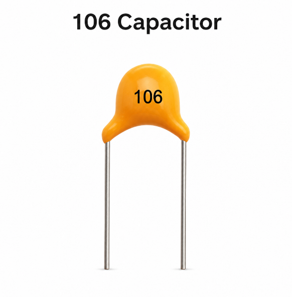
A 106 capacitor has a capacitance value of 10 uF, which equals 10,000 nF or 10,000,000 pF. The number “106” follows the standard three-digit capacitor code rule: the first two digits are the base number, and the third digit shows how many zeros are added in picofarads.
This guide explains the 106 capacitor value, capacitor code 106, voltage rating, tolerance, polarity, package size, datasheet parameters, testing method and replacement rules. It also adds practical PCB assembly advice, so the capacitor can be selected, mounted and tested correctly in real electronic products.
What Does 106 Mean on a Capacitor?
A 106 capacitor means the capacitor has a value of 10 uF. In the standard capacitor marking system, “10” is the significant number, and “6” means six zeros are added after it in picofarads.
The calculation is 10 × 10⁶ pF = 10,000,000 pF. After unit conversion, this becomes 10,000 nF or 10 uF. This is why a capacitor marked 106 is not 106 pF, but a much larger 10 uF capacitor.
The 106 marking appears on ceramic capacitors, tantalum capacitors, electrolytic capacitors and SMD capacitors. However, this marking only identifies capacitance. Voltage rating, tolerance, polarity, dielectric material and package size must be checked separately before replacement or PCB assembly.
What Is the Value of a 106 Capacitor in uF, nF and pF?
The value of a 106 capacitor is 10 uF, equal to 10,000 nF and 10,000,000 pF. This conversion is the first thing to confirm when reading capacitor code 106 on a PCB or component body.
| Code | uF | nF | pF |
|---|---|---|---|
| 106 | 10 uF | 10,000 nF | 10,000,000 pF |
A 10 uF capacitor is commonly used for power decoupling, voltage smoothing, noise filtering and local energy storage. In power rails, it helps reduce voltage drops when ICs, modules or sensors suddenly draw current.
However, capacitance alone does not decide final performance. A 106 ceramic capacitor, 106 tantalum capacitor and 106 electrolytic capacitor can behave differently because ESR, leakage current, polarity, temperature performance and voltage derating are different.
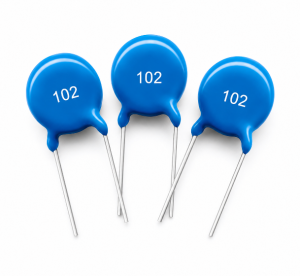
How to Read a 106 Capacitor Code?
A 106 capacitor code is read by using the first two digits as the base number and the third digit as the multiplier in picofarads. For 106, the value is 10 × 1,000,000 pF, which equals 10 uF.
If a letter appears after 106, it may show tolerance, voltage code, dielectric series or manufacturer-specific information. The meaning depends on capacitor type, so the datasheet should be checked when the marking is not fully clear.
| Marking | Common Meaning |
|---|---|
| 106 | 10 uF capacitance |
| 106J | 10 uF, often ±5% tolerance |
| 106K | 10 uF, often ±10% tolerance |
| 106M | 10 uF, often ±20% tolerance |
| 106C | 10 uF, may indicate a voltage code on some SMD tantalum capacitors |
| 106E | 10 uF, may indicate a voltage code on some SMD tantalum capacitors |
For PCB assembly, never approve a component only by the printed code. The full manufacturer part number should be used in the BOM to avoid wrong voltage, wrong package or wrong capacitor type.
Difference Between 105, 106 and 107 Capacitor
The difference between 105, 106 and 107 capacitors is capacitance value. 105 = 1 uF, 106 = 10 uF, and 107 = 100 uF.
| Code | Value | Conversion | Common Use |
|---|---|---|---|
| 105 | 1 uF | 1,000 nF | Small decoupling, timing, signal coupling |
| 106 | 10 uF | 10,000 nF | Power filtering, module decoupling, voltage smoothing |
| 107 | 100 uF | 100,000 nF | Bulk filtering, power input smoothing, energy storage |
Each code increases by 10 times. A 105 capacitor has lower energy storage than a 106 capacitor, while a 107 capacitor has much higher capacitance and may change startup current, charging time and PCB space.
In repairs, replacing 106 with 105 can reduce filtering capacity and cause ripple or reset problems. Replacing 106 with 107 may work in some power circuits, but it may also affect regulator stability, inrush current and cost.
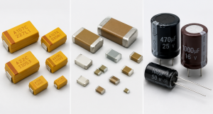
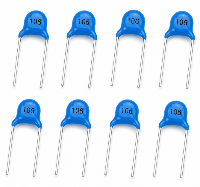
What Types of 106 Capacitors Are Common?
Common 106 capacitors include ceramic, tantalum, aluminum electrolytic and SMD capacitors. They all provide 10 uF capacitance, but their electrical performance, polarity and assembly risks are different.
- Ceramic type: low ESR, compact size, good for high-frequency decoupling near ICs.
- Tantalum type: stable capacitance, compact package, usually polarized and sensitive to surge.
- Electrolytic type: cost-effective for bulk filtering, usually larger and polarized.
- SMD type: suitable for automated SMT PCB assembly and compact electronic products.
- Through-hole type: used where manual assembly, mechanical strength or repairability matters.
For high-density PCB assembly, ceramic and SMD tantalum 106 capacitors are common. For power input filtering or low-cost products, electrolytic capacitors may be selected when board space allows.
Does a 106 Capacitor Have Polarity?
A 106 capacitor may or may not have polarity. Ceramic 106 capacitors are usually non-polarized, while tantalum and electrolytic 106 capacitors are usually polarized.
Non-polarized ceramic capacitors can be mounted in either direction. Polarized capacitors must be installed with the correct positive and negative orientation. Reverse installation can cause leakage current, overheating, short circuit, swelling or complete capacitor failure.
This is especially important in PCB assembly. Many SMD tantalum capacitors mark the positive terminal with a stripe, while many aluminum electrolytic capacitors mark the negative terminal with a stripe. Because marking rules are not always the same, the datasheet, PCB silkscreen and assembly drawing should be checked before production.
What Voltage Is a 106 Capacitor?
A 106 capacitor does not have one fixed voltage. The code 106 only identifies capacitance, while voltage rating depends on the actual capacitor series, package, dielectric material and manufacturer part number.
| Marking | Capacitance | Voltage |
|---|---|---|
| 106 6.3V | 10 uF | 6.3V |
| 106 10V | 10 uF | 10V |
| 106 16V | 10 uF | 16V |
| 106 25V | 10 uF | 25V |
| 106 35V | 10 uF | 35V |
| 106 50V | 10 uF | 50V |
For stable circuit operation, the voltage rating should be higher than the actual working voltage. In many PCB designs, a practical rule is to choose a capacitor with enough derating margin, especially when ripple, voltage spikes, high temperature or long service life are involved.
For example, a 10 uF 16V capacitor may be acceptable on a 5V rail, while a 10 uF 6.3V capacitor may be risky if the rail has spikes or poor transient control.
What Is the Tolerance of a 106 Capacitor?
The tolerance of a 106 capacitor depends on the tolerance letter and component type. Common tolerance codes include J = ±5%, K = ±10% and M = ±20%.
| Marking | Value | Tolerance | Normal Range |
|---|---|---|---|
| 106J | 10 uF | ±5% | 9.5 uF–10.5 uF |
| 106K | 10 uF | ±10% | 9 uF–11 uF |
| 106M | 10 uF | ±20% | 8 uF–12 uF |
Tolerance affects the real capacitance value under standard test conditions. For power decoupling, ±10% or ±20% may be acceptable in many circuits. For timing, filtering, sensing or analog applications, tighter tolerance can improve circuit consistency.
Ceramic capacitors may also lose effective capacitance under DC bias. Therefore, a 10 uF ceramic capacitor may measure lower in actual operation, especially in small packages or higher-voltage circuits.
What Size Is a 106 Capacitor?
The size of a 106 capacitor depends on capacitor type, voltage rating, dielectric material, package code and temperature grade. A 10 uF low-voltage SMD ceramic capacitor may be small, while a 10 uF high-voltage electrolytic capacitor may be much larger.
| Type | Common Size |
|---|---|
| SMD ceramic capacitor | 0402, 0603, 0805, 1206 |
| SMD tantalum capacitor | A, B, C, D, E case |
| Aluminum electrolytic capacitor | 4 mm to 8 mm diameter or larger |
| Through-hole ceramic capacitor | varies by voltage and lead spacing |
Higher voltage ratings usually require larger packages. Higher reliability grades, wider temperature ranges and lower ESR versions may also increase size and cost.
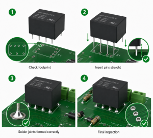
In PCB assembly, the selected capacitor must match the land pattern, height limit, polarity mark, pick-and-place capability and reflow soldering process. A wrong size can cause mounting failure, solder bridging, tombstoning or mechanical interference.
106 Capacitor Datasheet Overview
A 106 capacitor datasheet should be reviewed before replacement, purchasing or PCB assembly. The marking 106 confirms 10 uF, but the datasheet confirms whether the part can work safely in the target circuit.
| Parameter | Typical Information |
|---|---|
| Capacitance | 10 uF |
| Voltage rating | 6.3V, 10V, 16V, 25V, 35V, 50V |
| Tolerance | ±5%, ±10%, ±20% |
| Temperature range | -55°C to +85°C or +125°C |
| ESR | type and series dependent |
| Leakage current | material and voltage dependent |
| Package | SMD, radial, axial, case code |
| Polarity | polarized or non-polarized |
| Dielectric | X5R, X7R, tantalum, aluminum electrolytic |
| Compliance | RoHS, REACH, halogen-free options |
For mass production, the datasheet also helps confirm soldering profile, storage condition, MSL level, shelf life, reel packaging, ripple current and reliability rating.
A complete BOM should include the manufacturer part number, value, voltage, tolerance, package, dielectric type and approved alternatives. This reduces purchasing mistakes and improves PCB assembly yield.
Where Is a 106 Capacitor Commonly Used?
A 106 capacitor is commonly used for power filtering, decoupling, voltage stabilization, ripple reduction and short-term energy storage. Its 10 uF value is large enough for many local power rails while still available in compact packages.
- MCU power rails: reduces voltage drops and random reset problems.
- Wireless modules: supports current peaks in Wi-Fi, Bluetooth, GPS and IoT devices.
- Power supplies: smooths ripple and improves transient response.
- Sensor circuits: stabilizes analog and digital supply lines.
- LED drivers: helps reduce flicker and supply fluctuation.
- Automotive electronics: supports stable operation under vibration and temperature change.
- Industrial control PCB: improves noise immunity and long-term reliability.
In PCB layout, a 106 capacitor is often placed near IC power pins, regulators, connectors, sensors and communication modules. Short traces and good grounding improve its filtering effect.
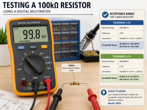
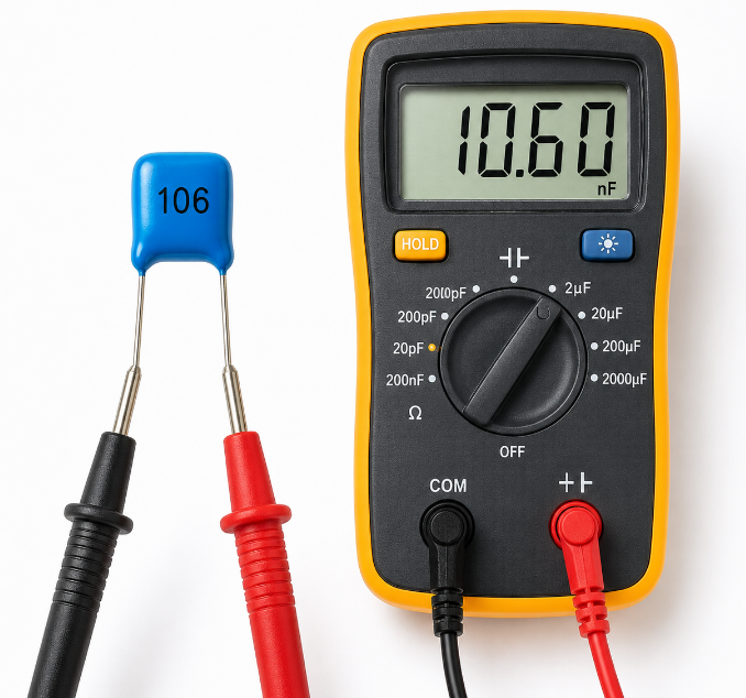
How to Test a 106 Capacitor with a Multimeter?
To test a 106 capacitor with a multimeter, first confirm that the circuit is powered off and the capacitor is safely discharged. A 106 capacitor should normally measure close to 10 uF, but the acceptable range depends on its tolerance.
- Turn off the power first
Disconnect the device from the power source before testing. Testing a charged capacitor may damage the multimeter or cause unsafe discharge. - Discharge the capacitor safely
Use a suitable resistor to discharge the capacitor before measurement. Do not short the terminals directly, especially for larger capacitors or power supply circuits. - Check whether it is still on the PCB
If the capacitor remains soldered on the PCB, nearby components may affect the reading. For a more accurate result, remove one terminal or test the capacitor after desoldering it. - Set the multimeter to capacitance mode
Select the capacitance function on the multimeter. Then connect the probes to the capacitor terminals. For polarized 106 capacitors, keep the probe direction correct if required by the meter. - Compare the measured value with 10 uF
A normal 106 capacitor should read close to 10 uF. For example, a 106K capacitor has ±10% tolerance, so a reading between 9 uF and 11 uF is usually acceptable. - Watch for abnormal readings
If the reading is 0 uF, extremely low, unstable, or overloaded, the capacitor may be shorted, open, aged, cracked or damaged. - Check ESR when capacitance looks normal
Some failed capacitors still show normal capacitance but have high ESR. In power circuits, high ESR can cause ripple, startup failure, voltage drop or unstable operation. - Inspect the capacitor body
Look for cracks, bulging, leakage, burn marks or broken terminals. Physical damage is often a clear sign that the capacitor should be replaced.
For PCB repair and production testing, capacitance measurement is only the first check. If the capacitor is used in a power rail, ESR, leakage current, polarity and circuit waveform should also be reviewed.
How to Replace a 106 Capacitor?
To replace a 106 capacitor, do not choose a new part only by the “106” marking. The replacement must match 10 uF capacitance, voltage rating, tolerance, polarity, package size, capacitor type and circuit requirement.
- Match the capacitance value
A 106 capacitor equals 10 uF. The replacement should normally keep the same capacitance unless the circuit design allows a different value. - Choose the same or higher voltage rating
The replacement voltage should be equal to or higher than the original part. For example, a 10 uF 25V capacitor can often replace a 10 uF 16V capacitor if the size and type match. - Do not reduce the voltage rating casually
Replacing a 25V capacitor with a 16V capacitor may reduce reliability, especially in circuits with ripple, voltage spikes or high temperature. - Check polarity before soldering
Ceramic 106 capacitors are usually non-polarized, but tantalum and electrolytic 106 capacitors are usually polarized. Reverse mounting can cause leakage, overheating or failure. - Match the package size and footprint
The new capacitor must fit the PCB pad, height limit and assembly process. A wrong package may cause soldering defects, poor contact or mechanical interference. - Confirm the capacitor type
A 106 ceramic capacitor, 106 tantalum capacitor and 106 electrolytic capacitor may all be 10 uF, but their ESR, leakage current, polarity and stability are different. - Check ESR requirements
Some voltage regulators require a specific ESR range for stable output. Replacing tantalum with ceramic or electrolytic without checking ESR may cause oscillation or unstable voltage. - Review temperature and reliability grade
For industrial, automotive or outdoor PCB applications, choose parts with suitable temperature ratings such as -40°C to +105°C or -55°C to +125°C. - Use the full manufacturer part number
For PCB assembly, the BOM should include the full part number, voltage, tolerance, package, dielectric and approved alternatives. Listing only “106 capacitor” can cause purchasing mistakes. - Test the board after replacement
After soldering, check polarity, solder joints, capacitance and power rail behavior. Then run functional testing to confirm that the circuit starts and operates normally.
In PCB assembly, a correct replacement should not only match the 106 capacitor value. It should also support the circuit’s voltage, temperature, ESR, layout, sourcing and long-term reliability requirements.
How to Choose the Right 106 Capacitor for PCB Assembly?
Choose the right 106 capacitor by matching circuit performance, assembly process, reliability target and sourcing stability. The best capacitor is the one that works reliably after soldering, testing and long-term operation.
- Confirm circuit function: use ceramic for local decoupling, tantalum for stable compact filtering, and electrolytic for bulk smoothing.
- Check voltage margin: select a voltage rating higher than the actual rail voltage to reduce failure risk.
- Review tolerance: choose tighter tolerance for timing, analog and sensitive filtering circuits.
- Match package: confirm footprint, height, polarity and pick-and-place compatibility.
- Check ESR: regulator output capacitors may require a specific ESR range for stability.
- Consider temperature: use wider temperature grades for industrial, automotive and outdoor products.
- Control sourcing: list full manufacturer part numbers and approved alternates in the BOM.
- Verify production quality: use AOI, polarity inspection, ICT and functional testing to catch assembly defects.
For turnkey PCB assembly, the 106 capacitor should be checked during BOM review, incoming inspection and first-article testing. This prevents wrong-value mounting, reverse polarity, soldering defects and field reliability problems.
FAQs About 106 Capacitor
Q1: Is a 106 capacitor always 10 uF?
A1: Yes. In the standard three-digit capacitor code, 106 means 10 uF. It also equals 10,000 nF and 10,000,000 pF. However, the number 106 does not show voltage, tolerance, polarity or package size.
Q2: Is a 106 capacitor the same as a 106 pF capacitor?
A2: No. A 106 capacitor is not 106 pF. The third digit is a multiplier, so 106 means 10 × 10⁶ pF, which equals 10 uF. This is one of the most common capacitor code reading mistakes.
Q3: What does 106K mean on a capacitor?
A3: 106K usually means 10 uF with ±10% tolerance. Under standard test conditions, the measured capacitance may be around 9 uF to 11 uF. For purchasing or PCB assembly, the datasheet should still be checked.
Q4: What does 106J mean on a capacitor?
A4: 106J usually means 10 uF with ±5% tolerance. This tolerance is tighter than 106K and can be useful in circuits where capacitance accuracy affects timing, filtering or analog signal behavior.
Q5: What does 106C capacitor mean?
A5: A 106C capacitor usually means 10 uF, while “C” may be a voltage code or series code on some SMD tantalum capacitors. Since marking systems vary, confirm the exact voltage and case size from the datasheet.
Q6: What does 106E capacitor mean?
A6: A 106E capacitor usually indicates 10 uF, while “E” may represent a voltage code in some capacitor marking systems. It should not be treated as a universal rule because different manufacturers may use different coding methods.
Q7: Can I replace a 106 16K capacitor with a 106 25K capacitor?
A7: Usually yes, if the package, polarity, ESR and temperature rating match. Both are 10 uF ±10%, while 25V has a higher voltage rating than 16V. The main concern is whether the new capacitor fits the PCB footprint.
Q8: Can I replace a 106 25K capacitor with a 106 16K capacitor?
A8: Only if the circuit voltage is safely below 16V with enough margin. If the original capacitor was 25V, using 16V may reduce reliability under voltage spikes, ripple or high temperature. For production, avoid lowering voltage without approval.
Q9: Why does my 106 ceramic capacitor measure less than 10 uF?
A9: Ceramic capacitors, especially MLCC types, can lose effective capacitance under DC bias. A marked 10 uF capacitor may show a lower value in real operation, especially when the package is small or the applied voltage is high.
Q10: Does a 106 capacitor have positive and negative terminals?
A10: It depends on the capacitor type. Ceramic 106 capacitors are usually non-polarized, while tantalum and electrolytic 106 capacitors are usually polarized. For polarized capacitors, wrong orientation can cause overheating, leakage or failure.
Q11: What happens if a 106 capacitor is installed backwards?
A11: If the capacitor is polarized, reverse installation can cause serious failure. The capacitor may heat up, leak, short circuit or fail during power-on testing. This is a major risk for 106 tantalum capacitors and 106 electrolytic capacitors.
Q12: Which is better, 106 ceramic capacitor or 106 tantalum capacitor?
A12: A 106 ceramic capacitor is better for low ESR and high-frequency decoupling. A 106 tantalum capacitor may provide more stable capacitance in compact power rails. The better choice depends on voltage, ESR, polarity, ripple and reliability requirements.
Q13: Can a wrong 106 capacitor cause PCB failure?
A13: Yes. A wrong 106 capacitor can cause unstable voltage, ripple, regulator oscillation, startup failure, repeated resets or wireless module dropouts. During PCB testing, engineers should check value, voltage, ESR, polarity, soldering and waveform behavior.
Q14: What should buyers check before ordering 106 capacitors?
A14: Buyers should check 10 uF value, voltage rating, tolerance, package, polarity, dielectric type, manufacturer part number, compliance and lifecycle status. For PCB assembly, the BOM should never list only “106 capacitor.”
Q15: Is a 106 capacitor suitable for industrial PCB assembly?
A15: Yes, if the part matches the working environment. Industrial PCB projects often require higher voltage margin, wide temperature range, stable sourcing, strong soldering control and strict inspection for long-term reliability.
Conclusion
A 106 capacitor has a value of 10 uF, equal to 10,000 nF or 10,000,000 pF. The code 106 only confirms capacitance, while voltage rating, tolerance, polarity, package size, material type, ESR and temperature range must be checked separately. For PCB projects, the right choice should match circuit voltage, filtering purpose, assembly footprint, reliability target and approved sourcing requirements.
EBest Circuit is a China source factory and global PCB assembly manufacturer. We support BOM review, component sourcing, custom PCB assembly, quality inspection and bulk production for electronic projects using 106 capacitors and related components. Send your BOM, Gerber files and project requirements to sales@bestpcbs.com for a fast quotation and practical assembly support.