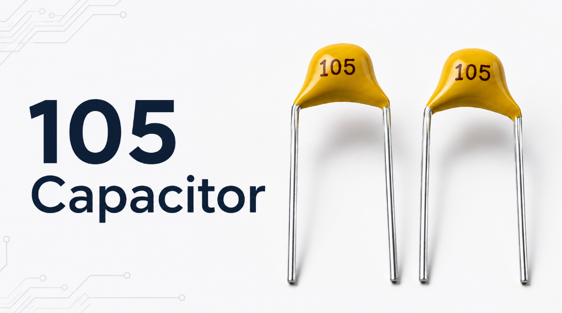
A 105 capacitor is a capacitor marked with the code 105, and its capacitance is 1 uF. It is the same value as 1,000 nF or 1,000,000 pF. The number 105 is a standard capacitor marking code, not a direct 105 pF value.
This guide explains the 105 capacitor value, code calculation, voltage rating, polarity, common types, replacement rules and PCB assembly risks. It also helps buyers and engineering teams avoid unclear BOM data, wrong component substitution, package mismatch and quality problems during production.
What Is a 105 Capacitor?
A 105 capacitor is a capacitor with a capacitance value of 1 uF, equal to 1,000 nF or 1,000,000 pF. The marking 105 is commonly used on ceramic, SMD, film, tantalum and electrolytic capacitors.
The code follows the standard three-digit capacitor marking rule. The first two digits are 10, and the third digit 5 means five zeros are added in picofarads. So 105 means 10 × 10⁵ pF.
In PCB assembly, this marking only confirms the nominal capacitance. It does not confirm voltage rating, tolerance, dielectric, package size, polarity or reliability grade. Therefore, two parts marked 105 may not perform the same in a real circuit.
A 105 capacitor is often used for power decoupling, noise filtering, signal coupling, timing circuits and local energy storage. It is a common value in consumer electronics, industrial control boards, IoT modules, power circuits and communication PCBs.
What Does 105 Mean on a Capacitor?
105 on a capacitor means 10 followed by five zeros in pF, so the final value is 1,000,000 pF. After unit conversion, it becomes 1,000 nF or 1 uF.
The first two digits form the base number, and the third digit is the multiplier. For the capacitor value 105, the base number is 10 and the multiplier is 10⁵. This gives the final capacitance value.
If a letter appears after 105, it usually shows tolerance. For example, 105J usually means 1 uF with ±5% tolerance, 105K usually means ±10%, and 105M usually means ±20%.
However, the marking does not tell the full story. A complete part check should include capacitance, voltage, tolerance, package, dielectric type, temperature rating and polarity.
What Value Is a 105 Capacitor in pF, nF and uF?
The value of a 105 capacitor is 1,000,000 pF, 1,000 nF or 1 uF. These are the same capacitance value written in three different units.
| Code | pF | nF | uF | F |
|---|---|---|---|---|
| 105 | 1,000,000 pF | 1,000 nF | 1 uF | 0.000001 F |
This conversion is important because different documents use different formats. A schematic may show 1 uF, a supplier page may show 1000 nF, and a calculator may show 1,000,000 pF.
The 105 capacitor value in nF is 1,000 nF. The 105 capacitor value in uF is 1 uF. The 105 capacitor value in microfarad is also 1 microfarad.
For purchasing and PCB Assembly, value matching is only the first step. The correct component must also match voltage rating, tolerance, dielectric material, package size, polarity and operating environment.
How to Read the 105 Capacitor Code?
The 105 capacitor code is read as 10 × 10⁵ pF, which equals 1 uF. This is the standard three-digit capacitor code value.
| Marking | Meaning | Value |
|---|---|---|
| 105 | 10 × 10⁵ pF | 1 uF |
| 105J | 1 uF, ±5% | 1 uF |
| 105K | 1 uF, ±10% | 1 uF |
| 105M | 1 uF, ±20% | 1 uF |
The first two digits show the base number. The third digit shows how many zeros are added after that number in picofarads. This rule is the same method used in many ceramic and film capacitor markings.
For PCB production, reading the code is not enough. A 105 ceramic capacitor and a 105 tantalum capacitor can have the same capacitance but different polarity, ESR, leakage current, surge tolerance and failure behavior.
To avoid sourcing errors, the BOM should list manufacturer part number, voltage, tolerance, dielectric, package size and approved alternatives, not only the printed marking.
How to Calculate the Value of a 105 Capacitor?
The value of a 105 capacitor is calculated by using this rule: first two digits × 10 to the power of the third digit, measured in pF.
For 105, the first two digits are 10. The third digit is 5. Therefore, the calculation is 10 × 10⁵ pF, which equals 1,000,000 pF.
Then convert the unit. Since 1,000 pF equals 1 nF, 1,000,000 pF equals 1,000 nF. Since 1,000 nF equals 1 uF, the final result is 1 uF.
A 105 capacitor value calculator will show the same result. The key point is that the third digit is a multiplier. This is why 105 does not mean 105 pF.
105 Capacitor Datasheet Overview
A 105 capacitor datasheet should be checked for capacitance, marking code, tolerance, voltage rating, dielectric, package size, temperature range, ESR, leakage current, insulation resistance and soldering condition. The code 105 only confirms the value, while the full datasheet confirms whether the part is suitable for the circuit and PCB Assembly process.
| Item | Data |
|---|---|
| Marking code | 105, 105J, 105K, 105M |
| Capacitance | 1 uF |
| Capacitance in pF | 1,000,000 pF |
| Capacitance in nF | 1,000 nF |
| 105J | 1 uF, ±5% |
| 105K | 1 uF, ±10% |
| 105M | 1 uF, ±20% |
| Voltage rating | 6.3V, 10V, 16V, 25V, 50V, 100V, 250V, 500V |
| Dielectric | X5R, X7R, Y5V, film, tantalum |
| Package | 0402, 0603, 0805, 1206, radial, axial |
| Temperature range | -55°C to +85°C or +125°C |
| Polarity | Non-polar for ceramic and film; polarized for tantalum and electrolytic |
| ESR | Depends on type, package and frequency |
| Leakage current | Lower for ceramic and film; higher for some electrolytic types |
| Insulation resistance | Checked for leakage and dielectric quality |
| Soldering method | SMT reflow, wave soldering or hand soldering |
| Common use | Decoupling, filtering, coupling, timing, power stability |
Is a 105 Capacitor the Same as a 105 pF Capacitor?
No, a 105 capacitor is not the same as a 105 pF capacitor. A 105 capacitor equals 1,000,000 pF, while 105 pF is only 105 pF.
This mistake usually happens when the marking is read as a direct value. In capacitor code rules, the third digit is not a normal number. It is the multiplier that tells how many zeros should be added.
If a 105 pF capacitor is used instead of a 105 capacitor, the capacitance becomes far too small. This can cause weak filtering, unstable power rails, wrong timing, poor coupling or circuit malfunction.
In PCB Assembly, this issue often comes from unclear BOM descriptions, manual replacement, mixed component storage or poor incoming inspection. Clear part numbers and first-article inspection can prevent this problem before mass production starts.
What Are Common 105 Capacitor Types?
Common 105 capacitor types include ceramic, SMD MLCC, film, tantalum and electrolytic versions. They may share the same value, but they are not automatically interchangeable.
- 105 ceramic capacitor: Common for bypassing, decoupling and noise filtering.
- 105 SMD capacitor: Common in SMT Assembly and compact PCB layouts.
- 105 film capacitor: Better for stable signal, timing and low-loss circuits.
- 105 tantalum capacitor: Compact and stable, but usually polarized.
- 105 electrolytic capacitor: Used when larger size and polarity are acceptable.
The 105 ceramic capacitor value is 1 uF. The 105 SMD capacitor value is also 1 uF. However, the real performance may change with dielectric type, voltage rating, package size and DC Bias.
For most modern PCB projects, a 105 ceramic capacitor or SMD MLCC is the first choice for local decoupling. For power hold-up, timing, audio or harsh environments, material selection should be reviewed more carefully.
Does a 105 Capacitor Have Polarity?
A 105 capacitor may be polarized or non-polarized. Ceramic and film 105 capacitors are usually non-polarized, while tantalum and electrolytic 105 capacitors are usually polarized.
A non-polar ceramic or film capacitor can be installed in either direction. This makes it suitable for general decoupling, bypassing, AC coupling and signal filtering.
A polarized tantalum or electrolytic capacitor must follow the positive and negative direction. Reverse installation can cause leakage current, overheating, swelling, short circuit or PCB damage.
For PCB Assembly, polarity should be confirmed from schematic symbols, PCB silkscreen, component datasheet and placement files. This is especially important when replacing a ceramic capacitor with a tantalum capacitor or when reviewing alternative parts.
What Voltage Is a 105 Capacitor?
A 105 capacitor does not have one fixed voltage. Common voltage ratings include 6.3V, 10V, 16V, 25V, 50V, 100V, 250V, 500V or higher.
| Circuit Voltage | Suggested Rating |
|---|---|
| 3.3V | 6.3V or higher |
| 5V | 10V or higher |
| 12V | 25V or higher |
| 24V | 50V or higher |
| 48V | 100V or higher |
The voltage rating should be higher than the actual circuit voltage. Using a lower voltage rating can cause leakage, dielectric breakdown, overheating or shortened service life.
For ceramic MLCC parts, voltage also affects usable capacitance. A higher-voltage or larger-package capacitor may keep more effective capacitance under DC Bias. This is why two 1 uF parts with different voltage ratings may behave differently in the same circuit.
For replacement, choose equal or higher voltage rating, matching footprint and suitable dielectric behavior.
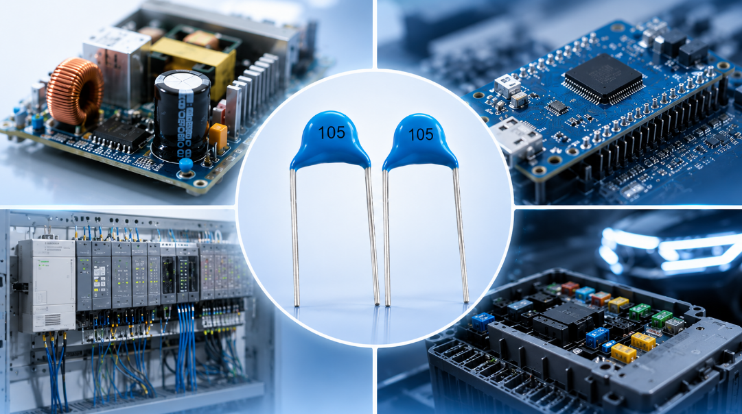
Where Are 105 Capacitors Commonly Used?
A 105 capacitor is commonly used in power decoupling, noise filtering, signal coupling, timing circuits, sensor modules, communication boards and industrial control PCBs.
- Power rails: Helps stabilize voltage near ICs and modules.
- MCU circuits: Reduces switching noise and random reset issues.
- IoT devices: Supports wireless modules, sensors and low-voltage rails.
- Audio circuits: Helps with signal coupling and noise reduction.
- Power supplies: Smooths ripple and transient noise.
- Automotive electronics: Supports stable operation under temperature and vibration.
In PCB Assembly, placement affects performance. A 105 SMD capacitor should usually be placed close to the load, with short traces and a clean ground path.
If the capacitor is placed too far away from the IC or power pin, the filtering effect may be reduced. Good layout practice can improve stability without changing the component value.
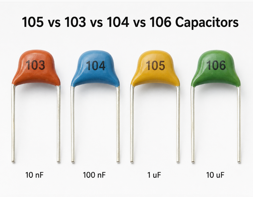
105 vs 103 vs 104 vs 106 Capacitors: What Is the Difference?
The difference between 105, 103, 104 and 106 capacitors is the capacitance value. 105 equals 1 uF, 103 equals 0.01 uF, 104 equals 0.1 uF, and 106 equals 10 uF.
| Code | pF | nF | uF |
|---|---|---|---|
| 103 | 10,000 pF | 10 nF | 0.01 uF |
| 104 | 100,000 pF | 100 nF | 0.1 uF |
| 105 | 1,000,000 pF | 1,000 nF | 1 uF |
| 106 | 10,000,000 pF | 10,000 nF | 10 uF |
These capacitors are often used together rather than replacing each other. A 104 capacitor may respond better to higher-frequency noise, while a 105 capacitor provides more local energy storage. A 106 capacitor may be used for larger power smoothing.
Therefore, these codes should not be treated as simple substitutes. The correct value depends on circuit function, noise frequency, load current and stability requirement.
How to Choose the Right 105 Capacitor for Your Circuit?
Choose the right 105 capacitor by matching capacitance, voltage, tolerance, dielectric, package, polarity, temperature range and circuit function.
- Confirm the circuit role.
Decoupling, filtering, coupling and timing circuits have different requirements. A general ceramic capacitor may work for power rails, while a timing circuit may need tighter tolerance and better stability. - Select enough voltage margin.
The voltage rating should be higher than the real working voltage. For a 12V circuit, 25V or higher is often safer than 16V. - Check dielectric stability.
X7R is usually more stable than Y5V. For MLCCs, DC Bias can reduce real capacitance, especially in smaller packages. - Match the PCB footprint.
0402, 0603, 0805 and 1206 packages affect placement accuracy, solder joint quality, voltage options and capacitance stability. - Confirm polarity before substitution.
A non-polar ceramic capacitor should not be replaced with a polarized tantalum capacitor unless the circuit direction and surge condition are reviewed. - Control approved alternatives.
In mass production, use a clear AVL to prevent random changes in brand, dielectric, voltage rating or package.
For B2B PCB projects, the BOM should include capacitance, voltage, tolerance, dielectric, package and manufacturer part number. This makes sourcing, inspection and assembly more reliable.
How to Replace a 105 Capacitor Without Causing Circuit Problems?
To replace a 105 capacitor safely, match 1 uF capacitance, equal or higher voltage rating, same footprint, suitable dielectric, correct tolerance and correct polarity.
- Identify the original capacitor type.
Check whether it is ceramic, film, tantalum or electrolytic. The same marking can appear on different capacitor structures. - Confirm the real circuit function.
A capacitor near an IC power pin may be for decoupling. A capacitor in a signal path may affect frequency response. A timing capacitor may affect delay or oscillation. - Match voltage and package.
Do not use a lower voltage rating. Do not choose a different package unless the PCB footprint and soldering process allow it. - Check polarity and surge risk.
Polarized tantalum or electrolytic capacitors must match the PCB direction. Surge current should be reviewed in power circuits. - Test the PCB after replacement.
Check startup behavior, ripple voltage, temperature rise, signal performance and long-term operation.
This process avoids hidden issues that visual inspection may not reveal. A wrong replacement may pass a simple power-on test but fail later under heat, load or vibration.
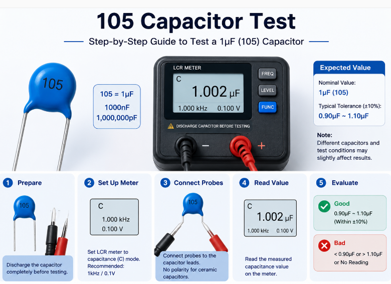
How to Test a 105 Capacitor Before or After PCB Assembly?
A 105 capacitor can be tested through incoming inspection, capacitance measurement, visual inspection, in-circuit testing and functional PCB testing. The goal is to confirm that the correct 1 uF capacitor is used and that it works safely after assembly.
- Check the part before PCB Assembly.
Confirm the reel label, manufacturer part number, package size, voltage rating, tolerance and dielectric type. This prevents wrong reel loading before SMT production starts. - Measure capacitance with an LCR meter or capacitance meter.
A correct 105 capacitor should read close to 1 uF within its tolerance range. For example, a ±10% part may normally measure from 0.9 uF to 1.1 uF under proper test conditions. - Check ESR and leakage when required.
For power filtering, tantalum or electrolytic capacitors, ESR and leakage current may affect circuit stability. Ceramic capacitors usually have low ESR, but the exact value still depends on type, package and frequency. - Inspect soldering after PCB Assembly.
Use AOI or visual inspection to check solder joints, tombstoning, cracks, wrong position, missing parts and polarity errors. This is important for small SMD packages such as 0402, 0603 and 0805. - Use ICT or flying probe testing when available.
ICT and flying probe testing can help detect wrong value, open circuit, short circuit or placement problems. In-circuit readings may be affected by nearby components, so results should be reviewed carefully. - Run functional PCB testing.
Power on the board and check startup stability, ripple voltage, reset behavior, signal performance and temperature rise. This confirms whether the capacitor works correctly in the real circuit. - Perform first-article inspection before batch production.
Before mass PCB Assembly, verify that the correct 105 capacitor is placed at the correct location. This reduces batch failure caused by wrong material loading or incorrect placement files.
How to Avoid 105 Capacitor Selection Mistakes in PCB Assembly?
Avoid selection mistakes by controlling BOM clarity, AVL approval, package footprint, sourcing channel, polarity check and first-article inspection.
- Do not read the code as 105 pF.
The correct value is 1 uF, not 105 pF. - Do not ignore voltage rating.
Low voltage margin can lead to leakage, overheating, breakdown or early failure. - Do not replace X7R with Y5V blindly.
The nominal value may be the same, but effective capacitance and temperature stability can be very different. - Do not mix polarized and non-polarized parts.
A reversed tantalum capacitor can fail quickly and damage the PCB. - Do not approve unclear substitutes.
Random alternatives may change package size, dielectric material, tolerance, voltage or reliability grade. - Do not skip production inspection.
Wrong reels, wrong feeder setup and wrong placement can happen during SMT Assembly.
Most capacitor problems in PCB Assembly are caused by incomplete specifications, not by the capacitor code itself. A clear BOM and controlled inspection process reduce rework, delay and batch failure.
What Factors Affect 105 Capacitors Price?
The price of a 105 capacitor is affected by material, voltage rating, tolerance, package size, brand, certification, order quantity and market supply. For PCB Assembly purchasing, the lowest unit price is not always the lowest total cost.
- Material affects base price.
Ceramic capacitors are usually lower cost. Film and tantalum versions may cost more because of material structure, stability or application requirements. - Voltage rating affects cost.
A 50V or 100V part usually costs more than a 6.3V or 10V part. Higher voltage can also require a larger case size or better dielectric design. - Tolerance affects availability.
±10% and ±20% parts are usually easier to source. ±5% parts may cost more, especially when combined with higher voltage or special material. - Package size affects sourcing and SMT cost.
Common packages such as 0603, 0805 and 1206 are usually easier to buy. Very small packages or compact high-voltage parts may cost more during shortages. - Brand and certification affect reliability cost.
Automotive, medical and industrial projects may require traceable brands, stable batches and compliance documents. These parts cost more but reduce rework and field risk. - Order quantity affects unit price.
Full reel orders usually reduce unit cost. Small trial orders, urgent orders or mixed sourcing can increase the total assembly cost.
For procurement, compare total project cost instead of unit price only. A low-cost capacitor may create higher cost through unstable supply, wrong substitution, SMT rework or field failure.
FAQs About 105 Capacitors
Q1: Can a 1 uF capacitor replace a part marked 105?
A1: Yes, but only when the replacement also matches voltage rating, tolerance, dielectric, package size and polarity. The value alone is not enough for a safe replacement. In PCB Assembly, a correct equivalent should match both electrical and mechanical requirements.
Q2: Why do some 1 uF capacitors look much smaller than others?
A2: Size depends on package, voltage rating, dielectric material and capacitor type. A small SMD MLCC may be tiny, while a film or electrolytic capacitor with the same value can be much larger. Higher voltage ratings often require a larger body.
Q3: Can a 105 capacitor fail even when the value is correct?
A3: Yes. Failure can happen because of wrong voltage rating, poor soldering, PCB bending, reverse polarity, overheating or DC Bias issues. In production, value matching is only one part of quality control. Assembly process and part selection both matter.
Q4: Why is DC Bias important for small 1 uF ceramic capacitors?
A4: DC Bias can reduce the effective capacitance of MLCC capacitors when voltage is applied. A part marked 1 uF may deliver less capacitance in the real circuit. This matters in power rails, filtering circuits and compact PCB designs.
Q5: Should I choose X7R or Y5V for a 1 uF capacitor?
A5: X7R is usually preferred when better temperature stability and more reliable capacitance are required. Y5V may be cheaper, but its capacitance can change more with voltage and temperature. For stable PCB performance, X7R is often safer.
Q6: Why does a 105 capacitor show lower capacitance after soldering?
A6: Measurement conditions, DC Bias, temperature, tolerance and surrounding in-circuit components can affect the reading. If the capacitor was overheated, cracked or mechanically stressed during assembly, its performance may also change or fail.
Q7: Can several smaller capacitors replace one 1 uF capacitor?
A7: Sometimes yes. Several capacitors in parallel can create a combined capacitance close to 1 uF. However, ESR, layout, frequency response and available PCB space must be checked. This substitution should be reviewed before production.
Q8: Is a 105 capacitor suitable for high-frequency noise filtering?
A8: It can help, but it is often used together with smaller values such as 0.1 uF or 0.01 uF. Different capacitor values respond better at different frequency ranges. PCB layout and ground path also affect filtering performance.
Q9: What causes a 105 SMD capacitor to tombstone during SMT Assembly?
A9: Tombstoning can be caused by uneven solder paste volume, unbalanced pad design, poor placement accuracy or uneven heating during reflow. Small packages are more sensitive. Good stencil design and reflow control help reduce this defect.
Q10: How should 105 capacitors be stored before assembly?
A10: They should be stored in a dry, clean and controlled environment according to supplier requirements. Moisture, damaged reels, mixed labels and poor storage control can increase assembly risk. Reel label management is important for mass production.
Q11: Can a 105 capacitor be used in automotive electronics?
A11: Yes, but the part should meet the project’s reliability requirements. Automotive projects usually require suitable temperature rating, stable dielectric, traceable sourcing and controlled quality documents. Generic parts should not be used without approval.
Q12: Why does the same 105 capacitor price vary between suppliers?
A12: Price can vary because of brand, voltage rating, package, dielectric, stock condition, certification and order quantity. Some low-price parts may not provide stable traceability or consistent production batches, which can increase assembly risk.
Q13: What should be checked before approving an alternative 105 capacitor?
A13: Check capacitance, voltage, tolerance, dielectric, package, temperature rating, ESR, polarity, lifecycle status and supplier reliability. For PCB Assembly, the alternative should also fit the footprint and pass first-article inspection.
Q14: How can EBest reduce capacitor sourcing risk in PCB Assembly?
A14: EBest can review BOM data, check capacitor specifications, suggest approved alternatives, inspect incoming materials and control SMT Assembly quality. This helps reduce wrong substitutions, package mismatch, polarity errors and production delays.
Q15: When should I send my BOM for capacitor review?
A15: Send the BOM before PCB Assembly or before mass production sourcing. Early review helps identify missing voltage ratings, unclear package sizes, risky alternatives and obsolete parts. This reduces rework cost and shortens production preparation time.
Conclusion
A 105 capacitor means 1 uF, equal to 1,000 nF or 1,000,000 pF. Correct selection should match voltage rating, tolerance, dielectric, package size, polarity and PCB assembly requirements.
If your project needs reliable component sourcing and PCBA service, EBest can help review your BOM, source suitable capacitors and complete PCB assembly from our China source factory. For component procurement and PCBA service quotation, contact EBest Circuit today: sales@bestpcbs.com.