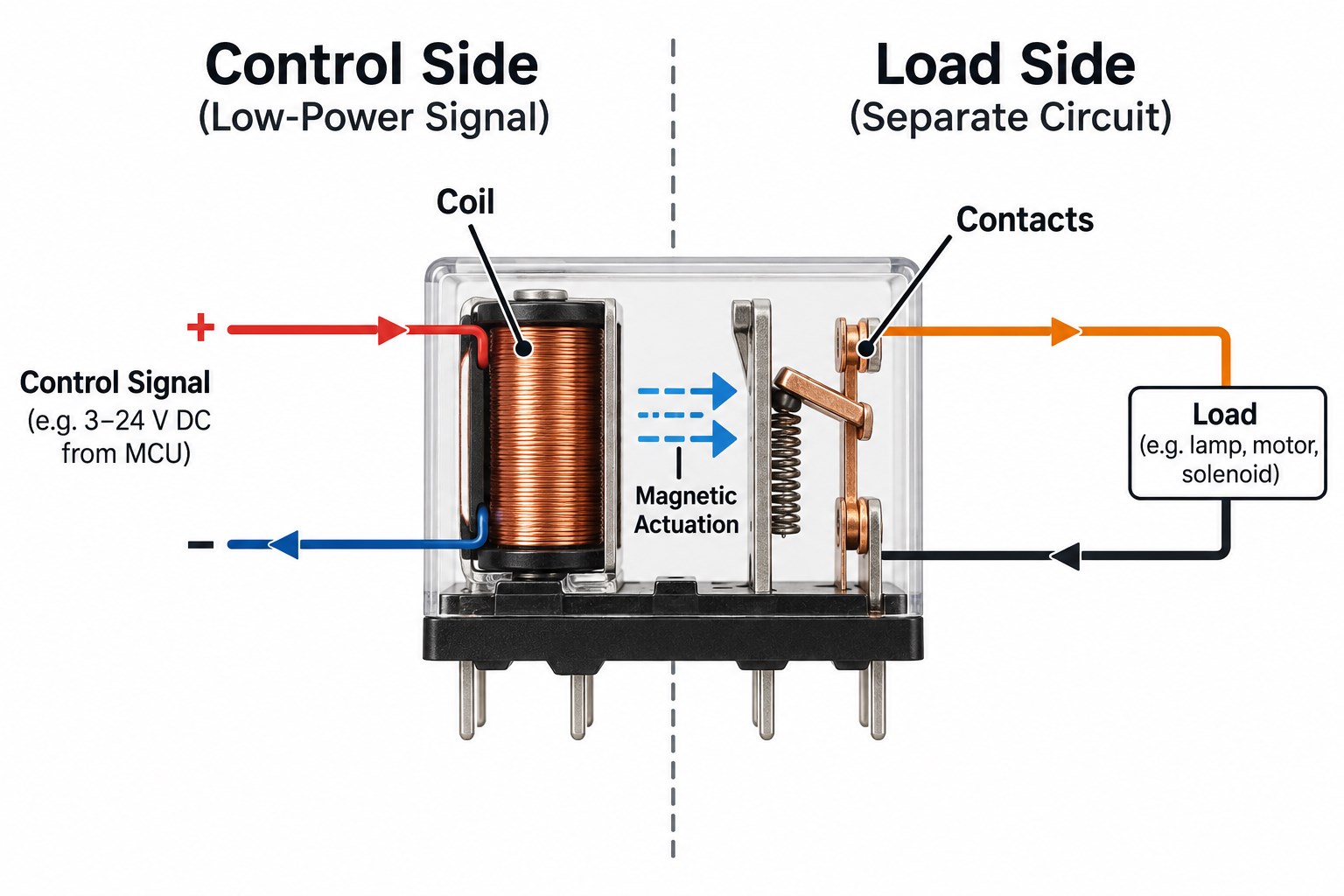
A relay diagram is easier to understand once you stop viewing the relay as one component and instead divide it into two sections. A low-power control circuit energizes the coil, while electrically separate contacts switch another circuit that may operate at a different voltage or carry much higher current.
This distinction explains most 4-pin, 5-pin, 8-pin, 14-pin, and 12V relay diagrams. The contact arrangement changes from one relay type to another, but the reading method stays similar: identify the coil, determine the contact form, confirm the pin numbering, and then check the actual device datasheet before wiring or PCB layout.
Key Takeaways
- A relay diagram shows how the relay coil controls one or more electrical contacts and how those contacts connect or disconnect the load circuit.
- The easiest way to read any relay is to separate it into a control side and a load side. The coil belongs to the control side; COM, NO, and NC belong to the switched side.
- On common automotive relays, terminals 85 and 86 are typically the coil, 30 is common, 87 is normally open, and 87a is normally closed.
- A common 4-pin automotive relay is usually SPST and normally open, while a common 5-pin version adds a normally closed contact and behaves as an SPDT relay.
- An 8-pin relay is often DPDT, while many 14-pin relays provide four changeover contact sets. Physical pin numbering is not universal, so the datasheet must still be checked.
- Relay schematic symbols, wiring diagrams, pin diagrams, and PCB footprints describe different things. A correct schematic can still produce a wrong PCB if the footprint orientation or pin mapping is mirrored.
- Coil polarity may matter when a relay contains an internal diode, LED, or other polarity-sensitive suppression component.
What Is a Relay Diagram?
A relay diagram shows the relay coil, switching contacts, terminal functions, and the electrical relationship between the control circuit and the load circuit.
Several diagram types are commonly called a “relay diagram,” although they provide different information:
- Schematic diagram: Shows electrical function.
- Wiring diagram: Shows how wires connect between devices.
- Pin diagram: Shows terminal or pin assignments.
- Internal relay diagram: Shows the coil and contact arrangement inside the relay.
- PCB footprint: Shows the actual pad or hole positions used for board layout.
A schematic may tell you that a relay is SPDT, but it does not necessarily tell you which physical pin is at the top-left corner of the package. That information comes from the relay pinout or package drawing.
This is why a relay diagram should always be matched to the exact relay model before wiring or creating a PCB footprint.
How Does a Relay Diagram Separate the Control Side from the Load Side?
A relay diagram normally separates the device into a control side containing the coil and a load side containing the contacts.
The relationship can be simplified as:
Control voltage → Coil → Magnetic force → Moving contact → Load circuit changes state
The coil is electrically isolated from the switched contacts in a conventional electromechanical relay. Applying the rated coil voltage creates a magnetic field that moves an armature and changes the contact position.
For example, a 12V control signal may energize a relay coil while the contacts switch a higher-current lamp, motor, pump, heater, or another circuit.
What Do Coil, COM, NO and NC Mean on a Relay Diagram?
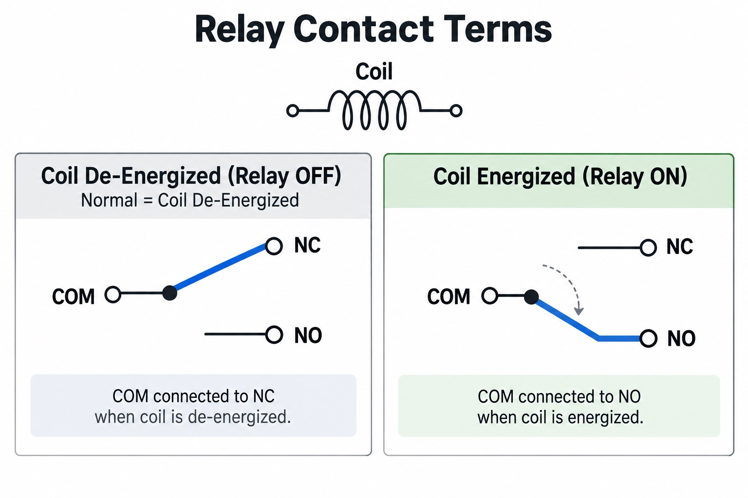
Coil, COM, NO, and NC describe the main functional parts found in common electromechanical relay diagrams.
| Marking | Meaning | Coil De-Energized |
|---|---|---|
| Coil | Electromagnetic control input | No magnetic actuation |
| COM | Common moving contact | Connected according to normal state |
| NO | Normally Open | Open |
| NC | Normally Closed | Connected to COM |
The word “normally” means the relay coil is not energized. It does not describe the state during normal machine operation.
In an SPDT relay, COM connects to NC when the coil is off. When the coil is energized, the contact moves away from NC and connects COM to NO.
Relay Diagram Symbols: How Do You Read the Coil and Contacts?
Relay symbols show the electrical relationship between the coil and the contacts rather than the physical appearance of the relay.
A schematic typically includes:
- A coil symbol
- One or more contact symbols
- NO or NC contact positions
- A dashed mechanical relationship between the coil and contacts
- A device designator such as K1, K2, RY1, or REL1
A dashed line between the coil and contacts represents mechanical linkage, not an electrical wire. When multiple contact sets share the same relay designation, one coil operates all of those contacts together.
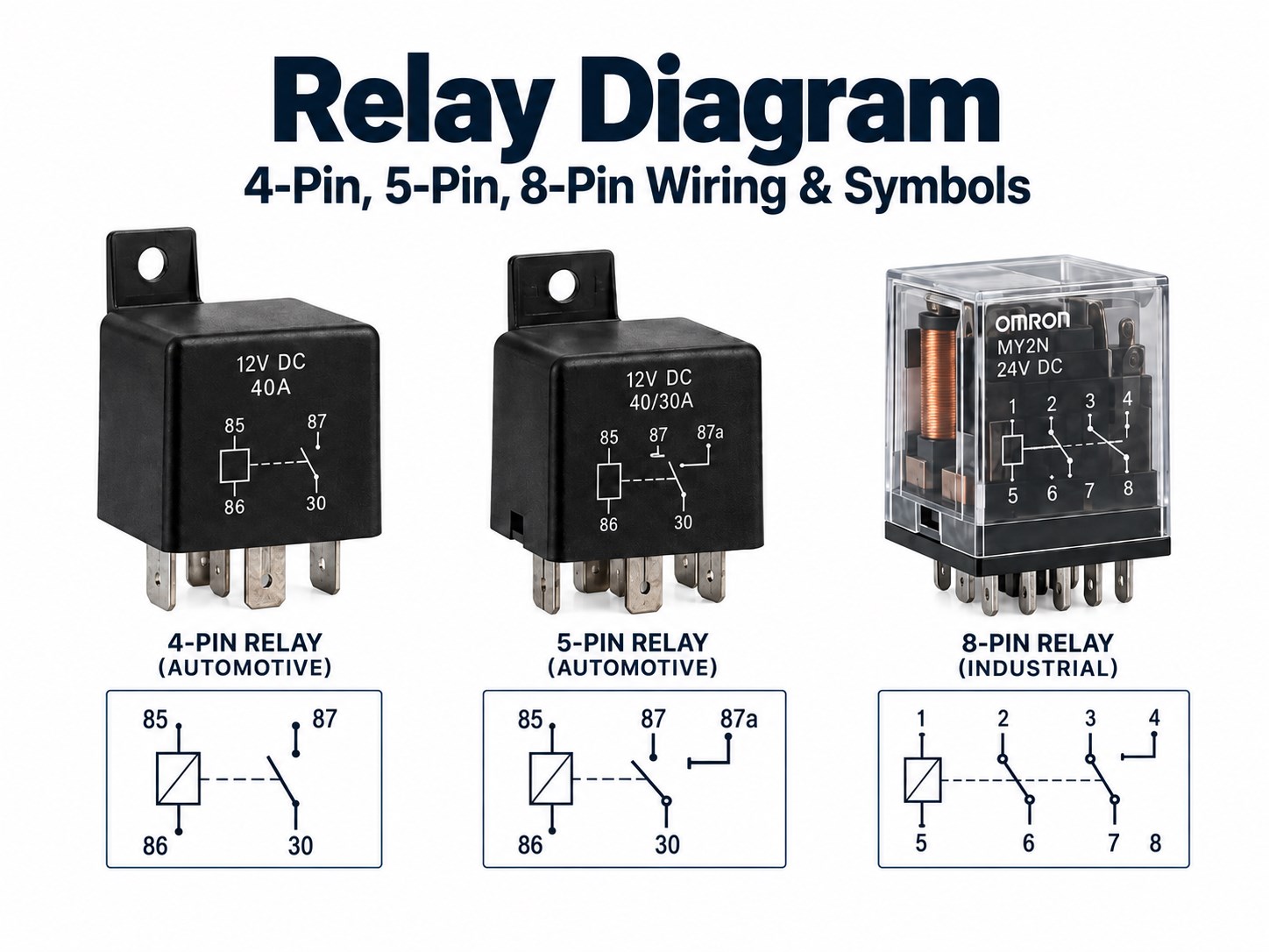
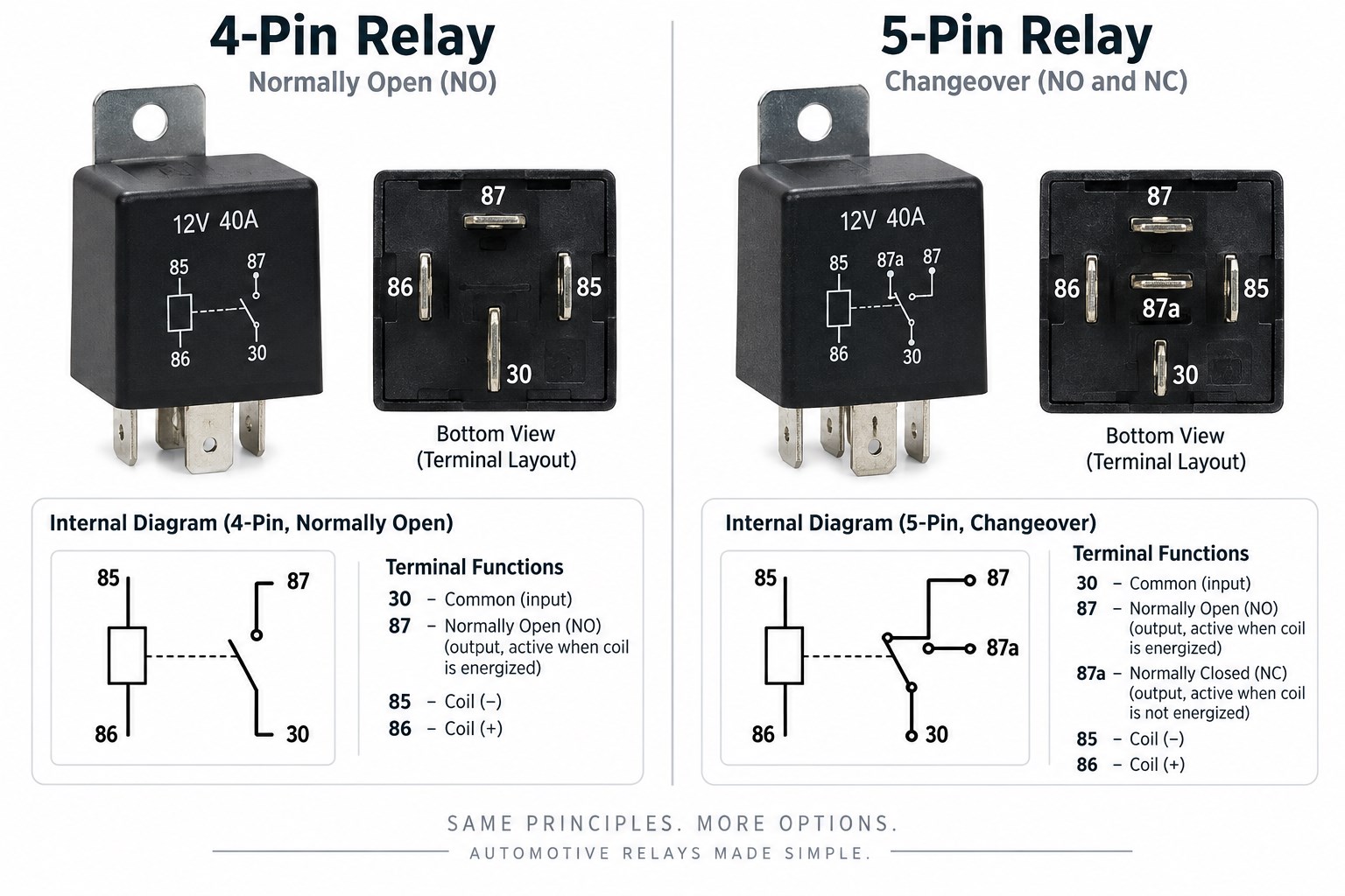
4-Pin vs 5-Pin Relay Diagram: What Do 30, 85, 86, 87 and 87a Mean?
A common automotive 4-pin relay uses terminals 30, 85, 86, and 87, while the common 5-pin changeover version adds terminal 87a.
A 4 pin relay diagram shows the coil and normally-open switching path. A 5 pin relay diagram adds the 87a normally-closed path.
| Terminal | Common Automotive Function |
|---|---|
| 85 | Coil |
| 86 | Coil |
| 30 | Common power contact |
| 87 | Normally open contact |
| 87a | Normally closed contact |
A typical 4-pin automotive relay is an SPST normally-open relay. With the coil off, 30 and 87 are open; when voltage is applied across 85 and 86, terminal 30 connects to 87.
A common 5-pin relay adds terminal 87a and usually operates as an SPDT changeover relay. With the coil off, 30 connects to 87a; when energized, 30 transfers to 87.
How Do You Read an 8-Pin Relay Diagram?
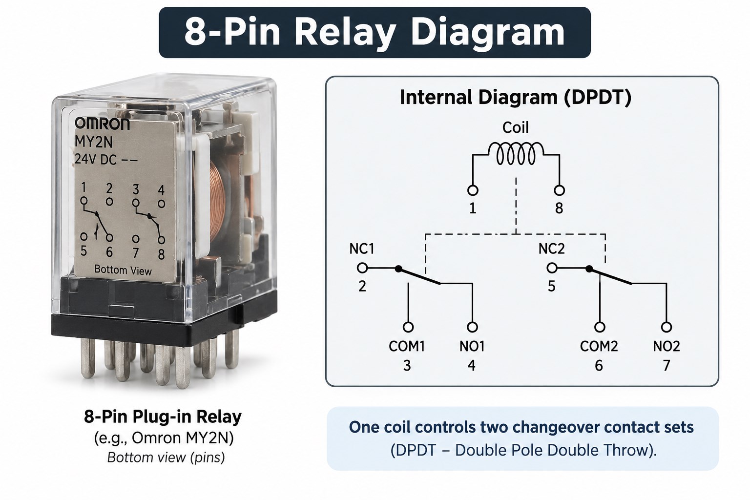
An 8-pin relay is commonly a DPDT relay containing one coil and two independent changeover contact sets. An 8 pin relay diagram therefore shows both contact sets operated by the same coil.
Its internal functions normally include:
- 2 coil terminals
- 2 COM terminals
- 2 NO terminals
- 2 NC terminals
That gives a total of eight pins. Conceptually, the relay contains two SPDT switches operated by the same coil.
There is no universal physical numbering arrangement for every 8-pin relay. The relay case diagram and datasheet should therefore be checked before connecting an 8-pin socket or creating a PCB footprint.
What Does a 14-Pin Relay Diagram Usually Show?
A 14-pin relay often provides four changeover contact sets operated by one coil, commonly described as 4PDT or 4CO.
A typical functional breakdown is:
- 2 coil terminals
- 4 COM terminals
- 4 NO terminals
- 4 NC terminals
That totals 14 electrical connections. These relays are common in industrial control panels, PLC interface circuits, interlocking systems, alarm circuits, machine control, and signal distribution.
As with 8-pin relays, the 14-pin count does not guarantee one universal physical pin sequence. Socket numbering and terminal arrangement must be verified against the exact part number.
How Do You Read a 12V Relay Wiring Diagram?
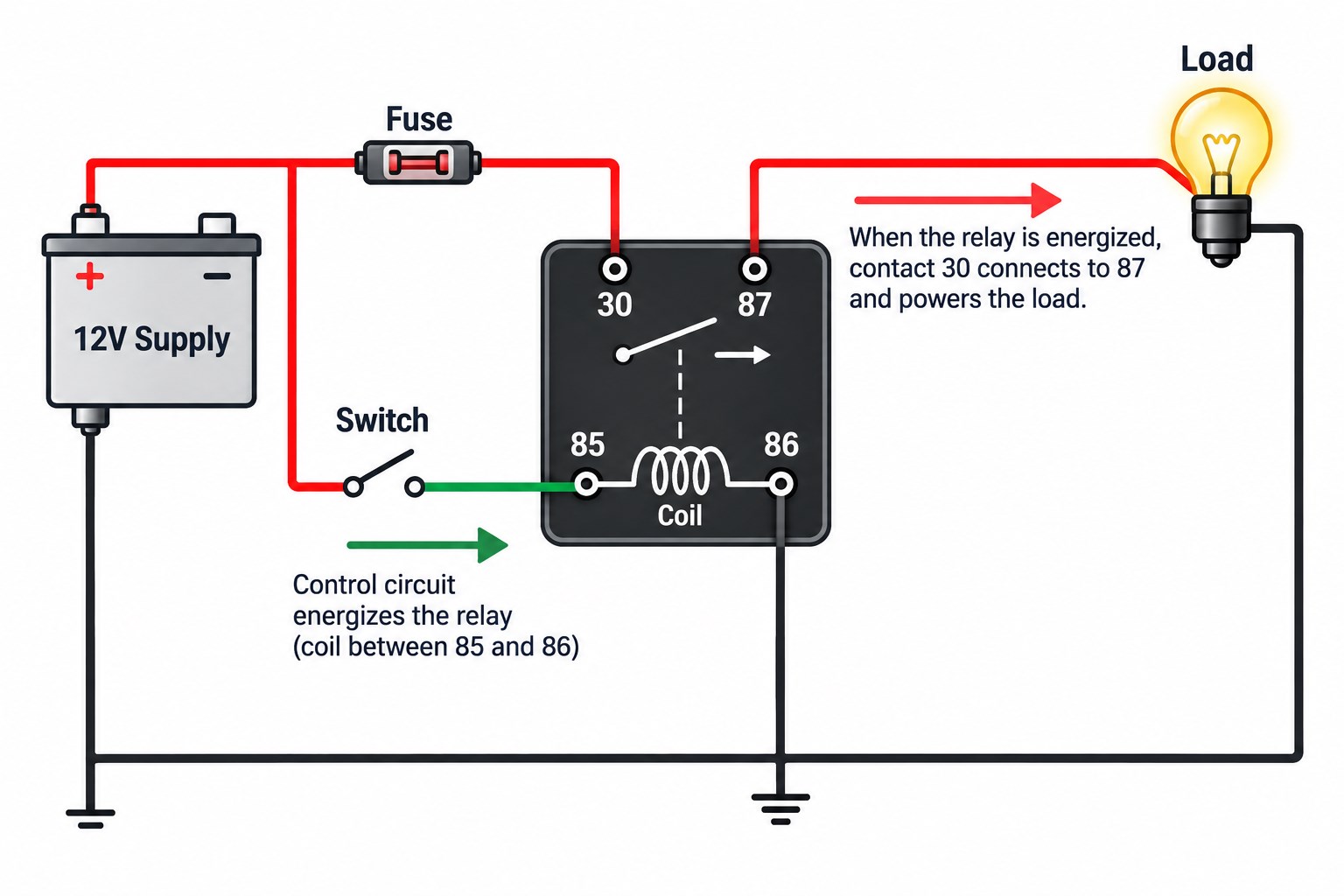
A 12V relay wiring diagram should be read by checking the coil circuit first and then tracing the switched load circuit.
- Confirm the coil voltage. Make sure the relay is actually rated for a 12V coil.
- Identify the coil pins. These may be 85/86 on automotive relays or A1/A2 on industrial designs.
- Identify COM, NO, and NC. Determine which contact state the application needs.
- Check coil polarity. A plain coil may not be polarity-sensitive, but an internal diode or LED can make polarity mandatory.
- Protect the control device. Use appropriate coil suppression when required.
- Fuse the load circuit. The relay does not replace proper overcurrent protection.
- Check contact current and voltage ratings. Motor and lamp loads may have high startup current.
- Confirm wire size and grounding. The wiring must suit the actual load current.
Where Are 4-Pin and 5-Pin Relay Diagrams Commonly Used?
Four-pin and five-pin automotive relay diagrams appear in many systems where a low-current control signal operates a higher-current electrical load.
| Application | Typical Relay Role |
|---|---|
| Horn | Switch controls higher-current horn circuit |
| Starter | Ignition/control path operates starter solenoid circuit |
| Fuel pump | ECU or control circuit switches pump supply |
| Auxiliary light | Dashboard switch controls lighting load |
| Cooling fan | Sensor or ECU controls fan motor |
| Compressor | Control circuit switches compressor clutch |
| Heater | Low-current controller switches heating load |
A horn relay, starter relay, fuel-pump relay, or driving-light relay still follows the same basic coil-and-contact logic. The application name does not define the internal relay pinout, so the actual relay markings must still be checked.
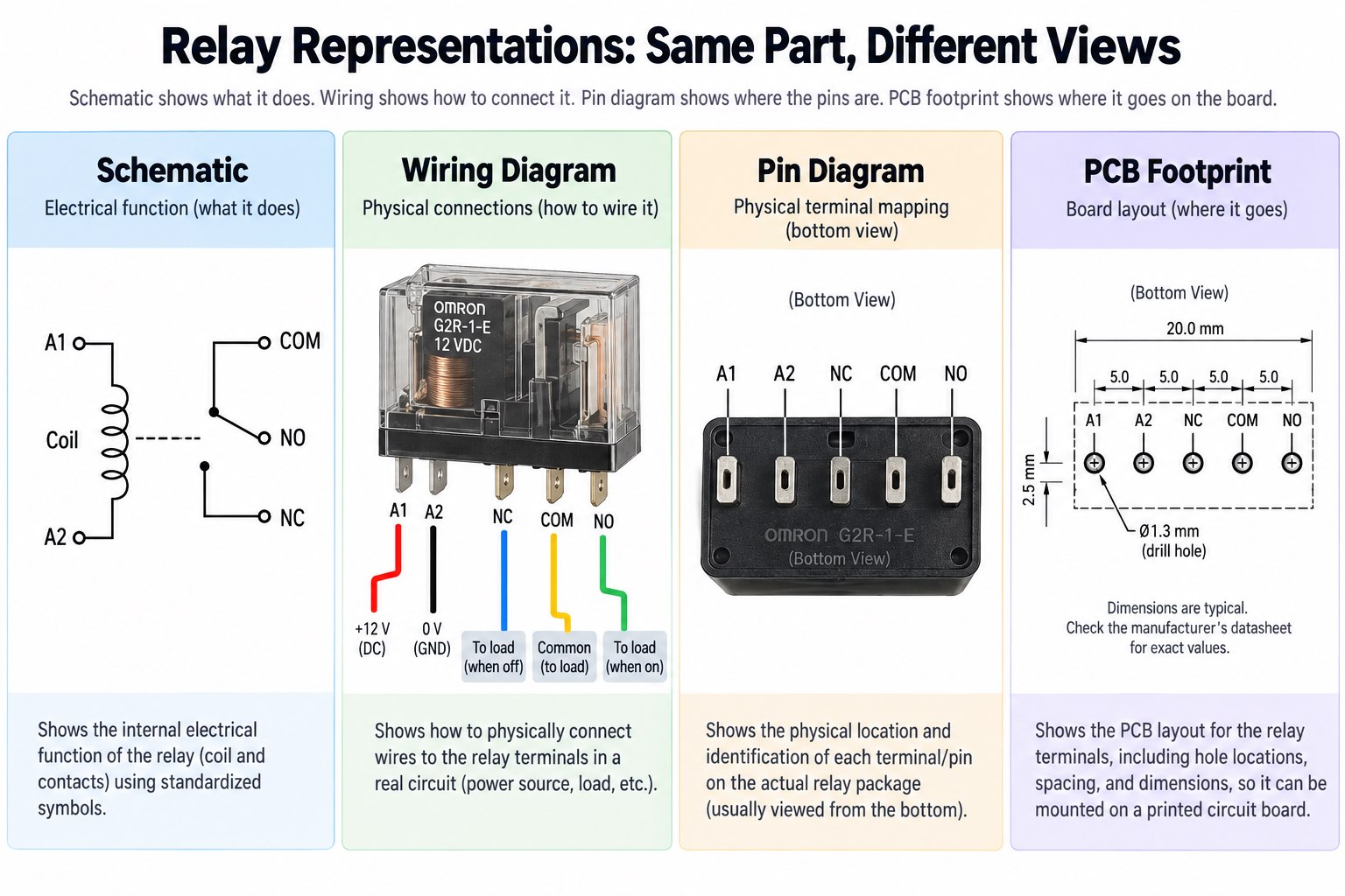
Relay Diagram vs Wiring Diagram vs Pin Diagram: What Is the Difference?
A relay schematic, wiring diagram, pin diagram, and PCB footprint answer different engineering questions.
| Diagram Type | Main Question It Answers |
|---|---|
| Relay schematic | What does the relay do electrically? |
| Wiring diagram | Where should each wire connect? |
| Pin diagram | Which physical terminal performs each function? |
| Internal diagram | How are the coil and contacts arranged? |
| PCB footprint | Where are the actual pads or holes? |
A schematic may show an SPDT relay as a coil plus COM, NO, and NC contacts. The wiring diagram then shows how those terminals connect to the power supply, switch, and load.
A relay pin diagram maps those functions to physical relay pins. Finally, the PCB footprint converts the mechanical package into copper pads or plated through holes.
What Should You Check Before Using a Relay Diagram for PCB Design?
Before placing a relay on a PCB, verify the physical pinout against the exact manufacturer datasheet rather than relying on a generic relay diagram.
Important checks include:
- Datasheet drawing orientation
- Top view versus bottom view
- Coil pin locations
- COM / NO / NC pin mapping
- Coil voltage
- Coil current
- Internal suppression components
- Contact current and voltage rating
- Load type
- Contact resistance
- PCB hole size
- Pad diameter
- Relay body clearance
The coil also affects the surrounding circuit. A microcontroller normally cannot drive many relay coils directly, so the PCB may need a BJT or MOSFET driver, base or gate resistor, flyback diode, LED indicator, optocoupler, or separate relay supply rail.
For higher-voltage loads, creepage and clearance between the control side and switched contacts must also be reviewed. A correct schematic symbol can still produce a wrong PCB if the footprint is mirrored or the physical pinout is interpreted from the wrong viewing direction.
EBest Circuit can review relay footprints, driver circuits, through-hole assembly, isolation spacing, trace current capacity, and PCBA requirements during DFM before fabrication.
FAQ About Relay Diagrams
1. What does a relay diagram show?
A relay diagram shows the relationship between the coil and switching contacts, including functions such as COM, NO, and NC.
2. What do 85 and 86 mean on a relay?
They are commonly the coil terminals on standard automotive relays. The actual relay marking or datasheet should still be checked.
3. What is the difference between a 4-pin and 5-pin relay?
A common 4-pin automotive relay provides a normally-open switching path, while a common 5-pin changeover relay adds terminal 87a for the normally-closed path.
4. What is an 8-pin relay diagram?
An 8-pin relay is commonly a DPDT relay with two changeover contact sets and one coil. Physical pin numbering varies by model.
5. Does relay coil polarity matter?
Not always. Polarity becomes important when the relay contains an internal diode, LED, or another polarity-sensitive suppression circuit.
6. Can I use the same relay diagram for every relay with the same number of pins?
No. The same pin count can be used by relays with different contact forms, internal features, and physical pin assignments. Always verify the exact datasheet.
Designing a PCB Around a Relay?
A relay diagram explains the electrical switching function, but reliable PCB implementation also depends on the actual footprint, coil driver, suppression method, load current, isolation spacing, and assembly process.
EBest Circuit supports relay control PCB fabrication, through-hole and SMT assembly, DFM review, component sourcing, and functional testing. If you have a similar control-board project, send your Gerber files, BOM, schematic, and relay specifications to sales@bestpcbs.com for engineering review.