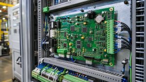
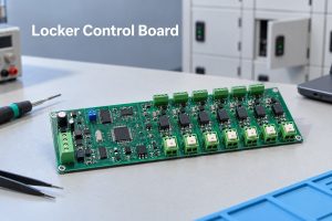
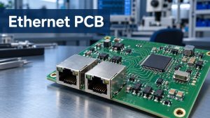
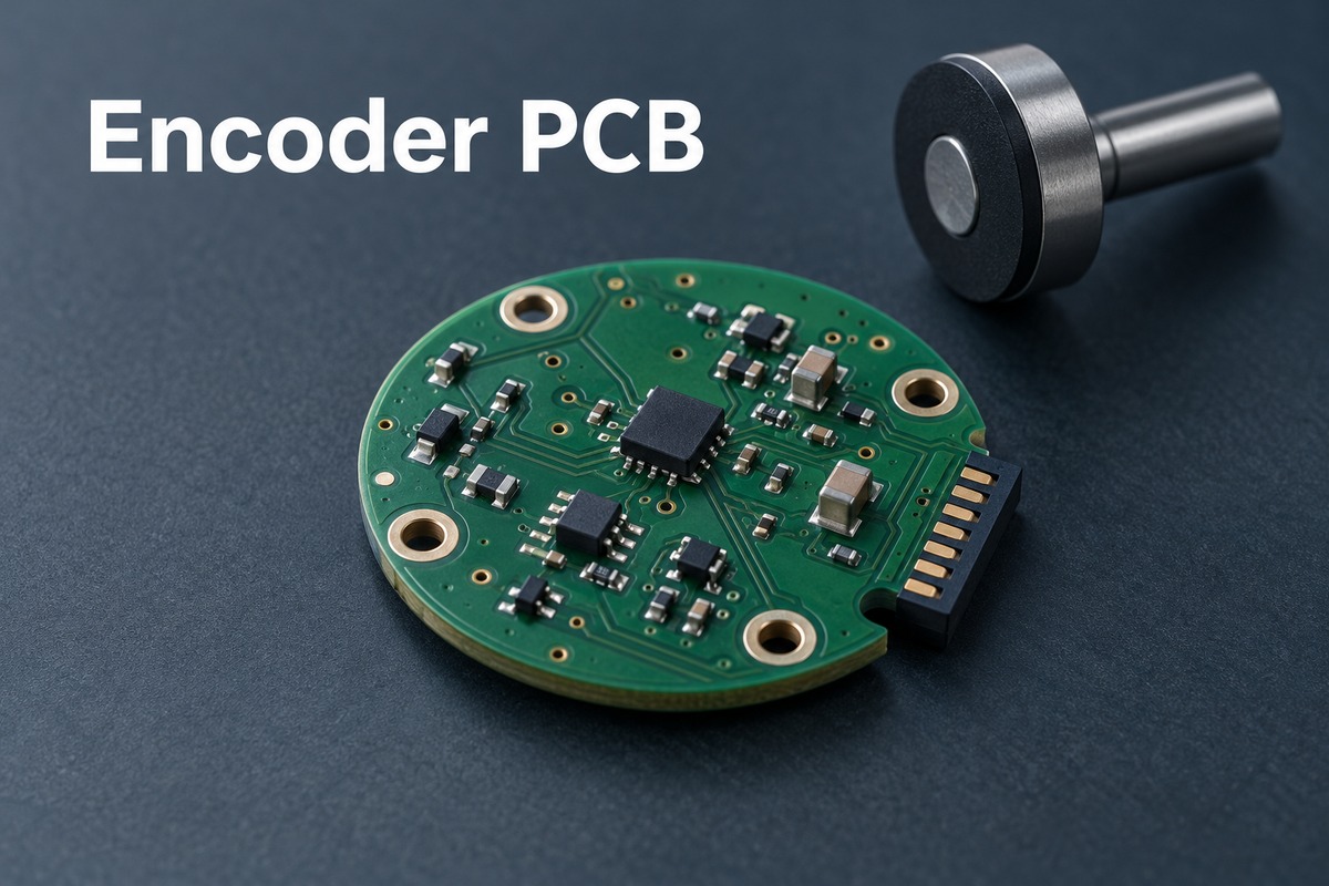
An encoder PCB supports the sensing, processing, or transmission of motion and position information in an encoder system. Depending on its role, it may carry a magnetic sensor, connect an optical readhead, form inductive sensing coils, or receive feedback from an external encoder. Understanding that role explains why two boards described as “encoder PCBs” can have very different structures and functions.
EBest Circuit (Best Technology) supports custom PCB fabrication, component sourcing, and PCB assembly for customer-approved electronics designs. For encoder boards, coordinating these services helps keep the fabricated board, specified components, and assembly requirements consistent from prototype to production. Discuss your manufacturing project with our team at sales@bestpcbs.com.
What Is an Encoder PCB?
An encoder PCB is a printed circuit board used within, or connected to, a system that measures motion or position. The term describes the board’s application; it does not identify one standard circuit or interchangeable product.
| Board role | What it does | Typical example |
|---|---|---|
| Sensor board | Holds sensing electronics and may process the detected position | A magnetic angle sensor board facing a shaft-mounted magnet |
| Breakout board | Routes an encoder’s pins to accessible connections | A rotary control board connected to microcontroller inputs |
| Interface board | Receives, protects, or conditions signals from an external encoder | A feedback input board in a servo controller |
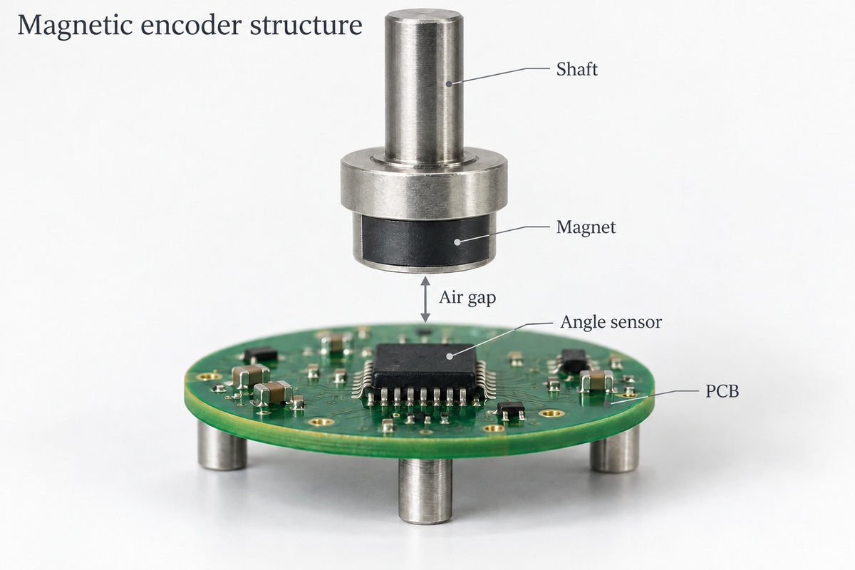
The bare PCB provides conductors and mechanical support. Once components are fitted, it becomes a PCB assembly, or PCBA. A complete encoder can also include a shaft, code disc, magnet, target, bearings, and housing.
In some inductive designs, copper patterns on the PCB form the sensing coils. Here, the board participates directly in measurement rather than only connecting separate components.
How Does a Rotary Encoder PCB Work?
A rotary encoder system turns shaft movement into signals that electronics can interpret. The PCB’s contribution depends on whether it performs sensing, provides connections, or receives signals elsewhere in the system.
A typical sensing path is:
Shaft rotation → changing optical, magnetic, or inductive response → signal processing → position or movement output
- Movement changes the sensed pattern. A code disc, magnet, or conductive target moves relative to the sensing element.
- Electronics convert that change into usable signals. Processing may include amplification, filtering, digitization, or angle calculation, depending on the design.
- The output reaches a controller. The controller can use it to track movement, regulate motor speed, or respond to a user turning a knob.
A simple mechanical rotary encoder works differently: contacts open and close as its shaft turns. A breakout PCB may only expose these contacts through headers. Pull-ups, contact debouncing, and movement decoding can then be handled by the connected controller and its software.
A board on the receiving side does not measure shaft rotation itself. Its job is to deliver the external encoder’s information reliably to the control electronics.
How Do Optical, Magnetic, and Inductive Encoder Boards Differ?
These technologies differ in how they detect movement. That difference changes the sensing components, mechanical arrangement, and conditions that can disturb the measurement.
| Technology | Sensing method | PCB role | Important limitations |
|---|---|---|---|
| Optical | Detects a light pattern from a coded disc or scale | Supports light-source, detector, and processing circuits as required by the architecture | Alignment and contamination in the optical path can affect performance; protection varies by encoder construction |
| Magnetic | Detects changes in a magnetic field as the target moves | Positions magnetic sensors and connects their processing and output circuits | Magnet position, field strength, gap, and external magnetic interference depend on the sensor design |
| Inductive | Detects changes in electromagnetic coupling caused by a conductive target | Can incorporate excitation and receiver coils directly into copper layers | Coil geometry, target position, gap, and nearby conductive material can influence the response |
These are not the only sensing methods. Mechanical contact and capacitive encoders also exist. A low-cost panel knob and a precision motor feedback encoder may therefore need very different board constructions.
The sensing technology does not, by itself, determine whether the output is incremental or absolute. That is a separate distinction about the position information the system provides.
What Is the Difference Between Incremental and Absolute Encoder Outputs?
Incremental outputs describe movement relative to a reference. Absolute outputs identify a position within a defined measurement range.
| Characteristic | Incremental output | Absolute output |
|---|---|---|
| Information supplied | Movement increments; quadrature channels also indicate direction | A position value associated with the measured location |
| Typical signal form | A/B pulse channels, sometimes with an index; analog sin/cos versions also exist | A position word through an interface such as SPI, SSI, or BiSS-C, depending on the encoder |
| Position after a power cycle | A lost count normally requires the system to establish its reference again | Position can be read within the supported absolute range without reconstructing every previous movement |
| Multiple revolutions | The controller accumulates movement counts while tracking remains active | A single-turn device repeats each revolution; multi-turn position requires additional capability |
With quadrature A/B signals, one channel leads the other. Reversing rotation reverses that sequence, allowing the controller to determine direction. An optional index pulse provides a reference event, commonly once per revolution.
For example, a 12-bit single-turn absolute encoder has 4,096 possible position codes within one revolution. That describes its nominal digital resolution, not a guarantee that every reported angle is accurate to one code step.
Single-turn absolute position also does not reveal how many complete turns occurred while power was off. Multi-turn behavior, retained counts, and unpowered movement tracking are specific product features.
How Does Encoder PCB Design Affect Position Feedback?
Encoder PCB design affects both the physical sensing relationship and the electrical quality of the feedback signal. A board can power up and communicate while still reporting unstable or inaccurate movement.
Five board-level details can change the result:
- Sensor and target alignment: Sensor placement must agree with the shaft, magnet, disc, or target location. Mounting-hole position, board seating, and component placement all contribute to the final relationship.
- Inductive coil geometry: When copper traces form sensing coils, their shape and layer arrangement are functional features. Changes to these patterns require review against the sensing design.
- Power and reference stability: Supply disturbance can affect sensitive circuitry or cause resets. Decoupling and return-current paths need to suit the selected devices.
- Coupling from switching circuits: Motor phases and switching power stages can disturb nearby feedback circuitry. Physical separation and suitable signal routing help reduce unwanted coupling.
- Output and receiver compatibility: Logic levels, differential receivers, protection, and termination must match the specified interface. A pin-compatible connector does not establish electrical compatibility.
The same layout prescription does not fit every encoder. A short mechanical knob connection has different requirements from a long industrial feedback cable or a PCB containing inductive coils. Layer count and controlled impedance should follow the actual sensing and interface requirements.
PCB quality helps preserve the intended design, but overall accuracy also depends on the sensor, target, mechanics, processing, and any required calibration.
How Are Encoder Boards Assembled and Tested?
Encoder board production combines accurate fabrication and assembly with tests suited to the board’s role. Continuity testing alone cannot demonstrate correct position feedback.
- Fabricate the defined geometry. The board outline, mounting features, conductive patterns, and stackup follow the released design. For inductive sensing boards, coil patterns receive particular attention.
- Place and solder components. Sensor orientation, connector direction, and component position must match the assembly data. A correctly soldered sensor can still be incorrectly oriented.
- Inspect the assembly. Inspection looks for missing or misplaced parts, solder bridges, poor joints, and other assembly defects. Mechanical registration to the target requires its own verification.
- Verify electrical operation. Power-rail and signal tests establish whether the assembled circuit operates as intended before motion-related measurements begin.
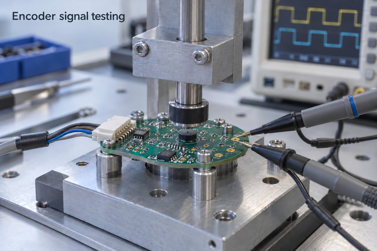
- Exercise the feedback function. A suitable fixture applies known movement, target positions, or simulated encoder signals and compares the response with agreed acceptance limits.
An incremental-board test may examine direction, pulse count, and index behavior. An absolute-board test may examine position data and communication. An interface board can be tested with generated signals, while validating a sensing board’s angle accuracy requires an appropriate mechanical reference.
EBest Circuit can coordinate fabrication, specified component sourcing, and assembly around the same released production data. Inspection and functional testing are defined for the project. Encoder calibration and full machine validation require the appropriate reference equipment and test scope; they are not established by a standard PCB electrical test.
FAQs About Encoder PCB
1. Is a PCB-mount encoder the same as an encoder PCB?
No. A PCB-mount encoder is a component intended to attach to a circuit board. An encoder PCB is the board used to support sensing, connections, or signal processing.
2. Can one encoder board replace another with the same connector?
Not necessarily. Pin assignments, supply voltage, output type, protocol, mechanical alignment, and firmware expectations can differ. Connector shape alone does not establish interchangeability.
3. What is the difference between PPR and CPR?
PPR commonly means pulses per revolution. CPR may mean counts or cycles per revolution, depending on the manufacturer. With four-edge quadrature counting, a device specified at 100 pulses per channel per revolution can produce 400 counts. The datasheet’s definitions determine the correct interpretation.
4. Does every rotary encoder require a magnet?
No. Magnetic encoders use magnetic sensing, while optical, inductive, capacitive, and mechanical contact encoders use other methods. The target and electronics depend on the technology.
5. Can a bare encoder PCB provide position feedback by itself?
Generally, no. Even a PCB with inductive coils needs excitation and signal-processing electronics, together with the appropriate target. A simple breakout PCB only provides connections for other components.
A reliable encoder PCB brings its sensing geometry, electrical interface, and assembly requirements together. For custom board fabrication and PCBA support based on your approved design, contact EBest Circuit at sales@bestpcbs.com.