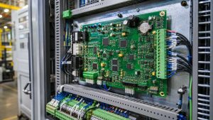
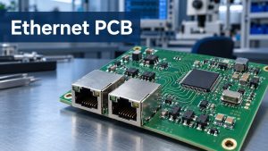
A locker control board is the electronic link between a smart locker’s host system and its individual doors. It receives an unlock command, drives the correct electronic lock, reads the resulting door or compartment status, and reports the result to the host. In a multi-door cabinet, these actions must remain reliable across every channel—not only on the first working prototype.
That makes the board more than a simple relay module. Its architecture must match the number and type of locks, the communication network, the available power supply, the sensing method, and the required test coverage. EBest Circuit supports prototype and production PCBA for customer-released locker controller designs. To discuss a project, send the PCB files, BOM and functional requirements to sales@bestpcbs.com.
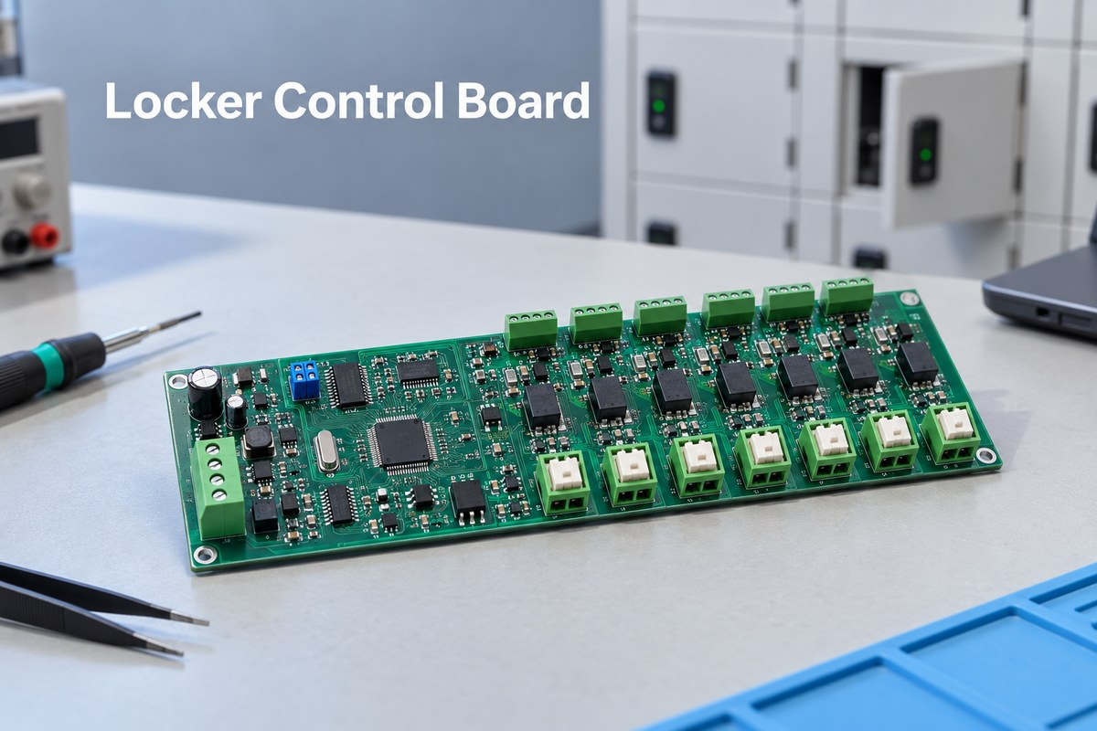
What Is a Locker Control Board?
A locker control board controls the electronic hardware inside parcel lockers, vending lockers, school lockers, pharmaceutical cabinets and other multi-compartment systems. It may operate as the main controller or as a lower-level unit connected to a separate computer or gateway.
Its role can be separated clearly:
- On the board: select a compartment, drive its lock, read door or occupancy signals, and control local indicators.
- Usually elsewhere: user interface, payment, cloud connection, access rules and management software.
This boundary prevents unnecessary functions from being added to the PCB and clarifies what the locker control board must exchange with the host system.
How Is a Smart Locker Control Board System Structured?
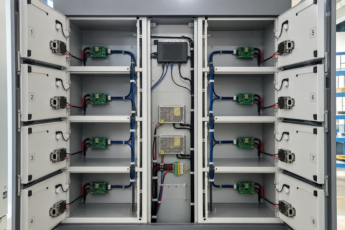
Many multi-door locker systems use a modular structure rather than putting every function on one large PCB.
- Host or main controller: Runs the user interface, access rules, network connection and application software.
- Communication or bus unit: Converts commands from Ethernet, USB or another host interface into a field bus such as RS485.
- Lock control unit: Provides multiple lock outputs and reads the corresponding feedback or sensor inputs.
- Locks and sensors: Perform the physical action and return door, latch or occupancy information.
Placing lock units near the compartments shortens high-current wiring. Additional addressed units can add more doors without redesigning the host controller.
Typical choice: combine the host interface and lock drivers for a compact locker; use one gateway plus several addressed lock boards for a large cabinet.
How Many Locks Can One Locker Control Board Manage?
Commercial locker boards commonly provide 8, 16 or 24 lock channels. Start with the compartment count: each door needs a lock output and the corresponding feedback and indicator connections. If the product family uses several cabinet sizes, a few spare channels can keep one controller platform usable across more than one model.
Then apply the electrical limit. The combined pulse current of every lock that may open together must remain within the PCB power path, connectors and external supply. For example, a 48-door cabinet can use two uniquely addressed 24-channel boards instead of concentrating 48 high-current outputs on one PCB. The “24-channel” label is meaningful only when the feedback I/O, power budget and bus architecture also support 24 doors.
How Do RS485 and TCP/IP Connect a Locker Control Board to the Host System?
TCP/IP and RS485 normally serve different links in the same system:
| Interface | Typical link | Main reason to use it |
|---|---|---|
| TCP/IP | Network or server to locker gateway | Connects management software and remote services |
| RS485 | Gateway to distributed lock boards | Supports addressed boards over longer cabinet wiring |
RS485 still requires the correct termination and biasing arrangement, transient protection where needed, controlled connector pinouts and a clear grounding strategy. The firmware protocol must define addresses, commands, acknowledgements and fault behavior. Adding a transceiver alone does not make the bus reliable.
How Does a Locker Control Board Monitor Doors and Compartments?
A locker control board monitors each compartment through separate inputs tied to the same channel number as its lock output. After the host commands channel 12, latch feedback can show that the lock released, a door switch can show whether door 12 actually opened, and an occupancy sensor can show whether the item was removed. The controller reports these events separately instead of returning one vague “success” status.
This separation lets the host distinguish an electrical release from a completed pickup. It can also identify cases such as “lock released but door stayed closed” or “door closed but latch not engaged.” The status LED is an output that communicates the resulting state to the user; it is not a substitute for the feedback inputs. Long sensor wiring may require filtering and protection so that noise does not create a false door event.
How Does a Locker Control Board Drive Solenoid and Motor Locks?
The two lock types need different drive behavior:
| Lock type | Typical drive action | Main PCB consequence |
|---|---|---|
| Solenoid lock | Apply a defined release pulse | Size the switching path for pulse current and suppress the inductive transient |
| Motor lock | Run for a controlled interval, sometimes with polarity reversal | Provide direction control and stop the drive at the correct time |
MOSFETs are commonly used for compact, efficient DC switching. Relays are more appropriate when the design needs isolated or flexible contacts, but they consume more board space and have a finite mechanical life. Whichever device is selected, the PCB power path, connectors and external supply must carry the worst-case current when multiple doors are released—not merely the current of one lock.
Does a Locker Control Board Need a 2-Layer or 4-Layer FR-4 PCB?
The common choice is 2-layer or 4-layer FR-4:
| PCB structure | Better suited to |
|---|---|
| 2-layer FR-4 | A roomy expansion board with modest channel count, low-speed communication and simple sensor inputs |
| 4-layer FR-4 | A compact controller combining an MCU, dense connectors, communication, many outputs and multiple inputs |
Four layers provide clearer ground and power planes and reduce routing congestion, but more layers do not automatically make a better controller. A roomy 8-channel board may work well in two layers, while a compact 24-channel controller may justify four. Freeze the stackup before final placement because a late layer change affects grounding, vias, routing and PCBA cost.
When Does a Locker Control Board Need HDI, Heavy Copper or BGA Assembly?
Most locker control boards need none of these three technologies. A conventional 2-layer or 4-layer FR-4 PCB with plated through holes and standard SMT packages is normally sufficient for a multi-channel lock controller.
HDI becomes justified only when the permitted board area and fine-pitch routing cannot be resolved with conventional through vias. Heavy copper becomes justified only when the simultaneous lock current cannot be carried practically with wider standard-copper pours and shorter power paths. In many locker designs, staged lock operation avoids that current concentration.
BGA assembly depends mainly on the selected processor rather than the locker application itself. A conventional MCU in QFP or QFN normally avoids BGA. A compact Linux controller that integrates processing, memory and networking is more likely to require BGA placement, X-ray inspection and escape routing. The design should add HDI, heavy copper or BGA only after a real space, routing or current limit rules out the conventional construction.
What Makes Multi-Channel Locker Control Board Assembly and Testing Difficult?
The challenge is repetition. A solder defect, incorrect connector, reversed driver device or wrong component value can affect only one of many otherwise identical channels. A board may power up and communicate normally while one locker door still fails in service.
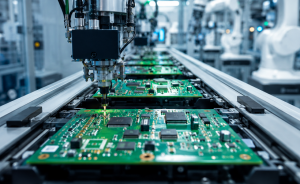
Mixed assembly can add another difficulty. Locker controllers often combine fine-pitch SMT control electronics with relays, terminal blocks, pin headers or other through-hole parts. The assembly process must keep polarity and orientation correct while protecting tall connectors and mechanically loaded joints.
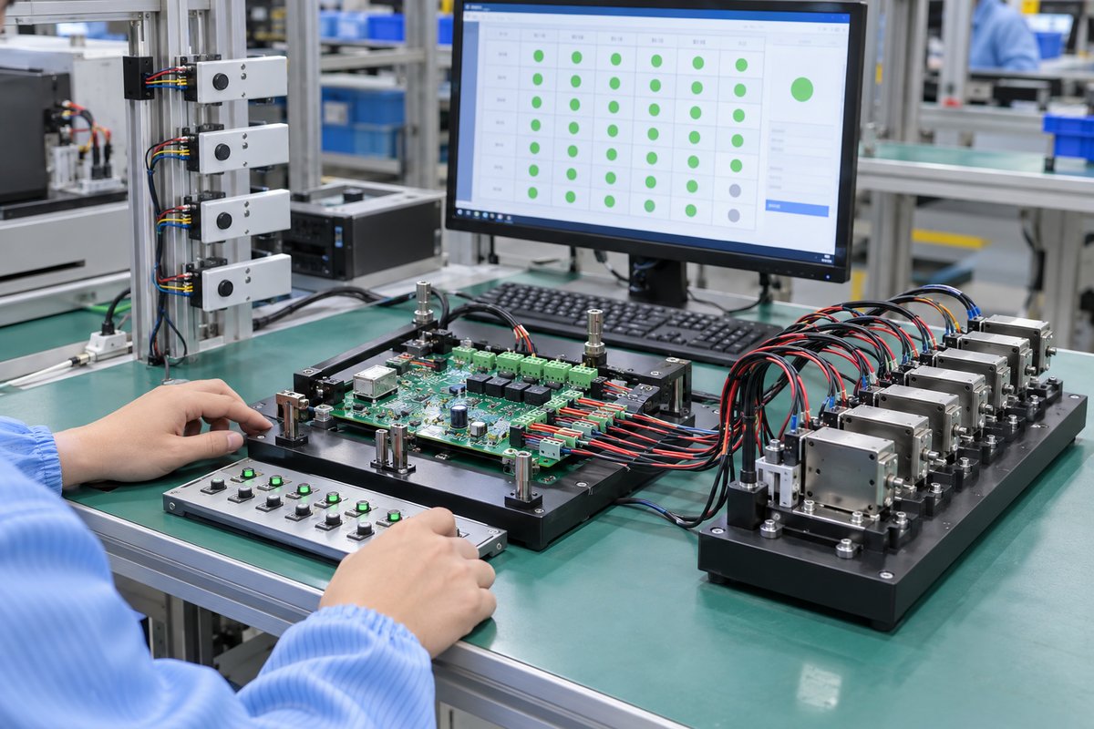
Visual inspection and continuity testing cannot demonstrate full operation. A production fixture should repeat one closed-loop sequence for every populated channel:
- Send a command to channel 1.
- Apply a representative lock load and confirm the output.
- Switch the paired door or occupancy input.
- Verify that the host reports channel 1.
- Repeat for every remaining channel.
Firmware revision and total supply current can be checked once for the complete board.
The fixture does not need dozens of physical locker doors. Electrical loads and switch simulation can test every channel efficiently, while a first article fitted with the actual lock confirms that the simulated current and feedback conditions represent the application.
How Does EBest Circuit Build and Test Multi-Channel Locker Control Board Assemblies?
The greatest manufacturing risk on a multi-channel locker board is that one repeated error can appear 8, 16 or 24 times. EBest Circuit reviews the repeated driver circuits, connector numbering, polarity and test-point access before assembly, helping prevent a mirrored connector or incorrect protection device from being copied across the complete board.
The prototype is built as a usable assembly rather than a bare PCB alone. PCB fabrication, sourcing through a network of more than 1,000 supply-chain partners, SMT and through-hole assembly can cover the MCU, communication devices, MOSFETs or relays, terminal blocks and cabinet connectors in one project. This allows the customer to connect the first articles to the intended locks and wiring before releasing the next quantity.
For production, the functional fixture follows the actual channel map. It verifies that each command activates the matching output and that the paired door or occupancy input returns to the correct address. Firmware revision, material batch and production progress can be linked through EBest Circuit’s digital workshop, where material and product batch information can be traced within five seconds.
With more than 20 years of PCB and PCBA experience, EBest Circuit supports prototypes, small batches and repeat orders under ISO 9001, ISO 13485, IATF 16949 and AS9100D quality systems. The practical benefit is a locker control board that arrives assembled, channel-tested and traceable, ready for the customer’s cabinet-level validation.
FAQs About Locker Control Board
Can one locker control board operate different types of electronic locks?
Yes, if the output circuit and firmware match the voltage, current, pulse duration and feedback method of each lock. A board designed for a low-current solenoid should not be assumed to support a motor lock without checking the driver and power architecture.
Is RS485 necessary for every smart locker?
No. A compact locker may connect its controller directly to the host. RS485 becomes especially useful when multiple lock boards are distributed through a larger cabinet or when the communication cable must cover a longer distance in a noisy environment.
Does a 24-channel board open all 24 locks at the same time?
Not necessarily. Channel count describes how many locks the board can address, not how many it can energize simultaneously. The permitted simultaneous operation depends on the output devices, copper distribution, connectors and external power supply.
Does a locker control board require a 4-layer PCB?
Not always. A simple expansion board may use two layers. Four layers are more appropriate when processing, communication, sensor inputs and many lock outputs create dense routing or demanding power and grounding needs.
What information is most useful for a locker control board PCBA quotation?
The PCB data, BOM, placement file and required quantity are enough to begin a manufacturing review. It also helps to identify the lock voltage and current, number of channels, programmed components, through-hole parts and expected functional test. EBest Circuit can review the available package first and identify any missing production details without asking the customer to prepare an unnecessary document set.
A reliable locker control board must do more than switch an electronic lock. It must control the correct channel, communicate consistently, read meaningful feedback and pass the same functional checks across every assembled board. For a locker controller PCB or PCBA review, contact EBest Circuit at sales@bestpcbs.com.