





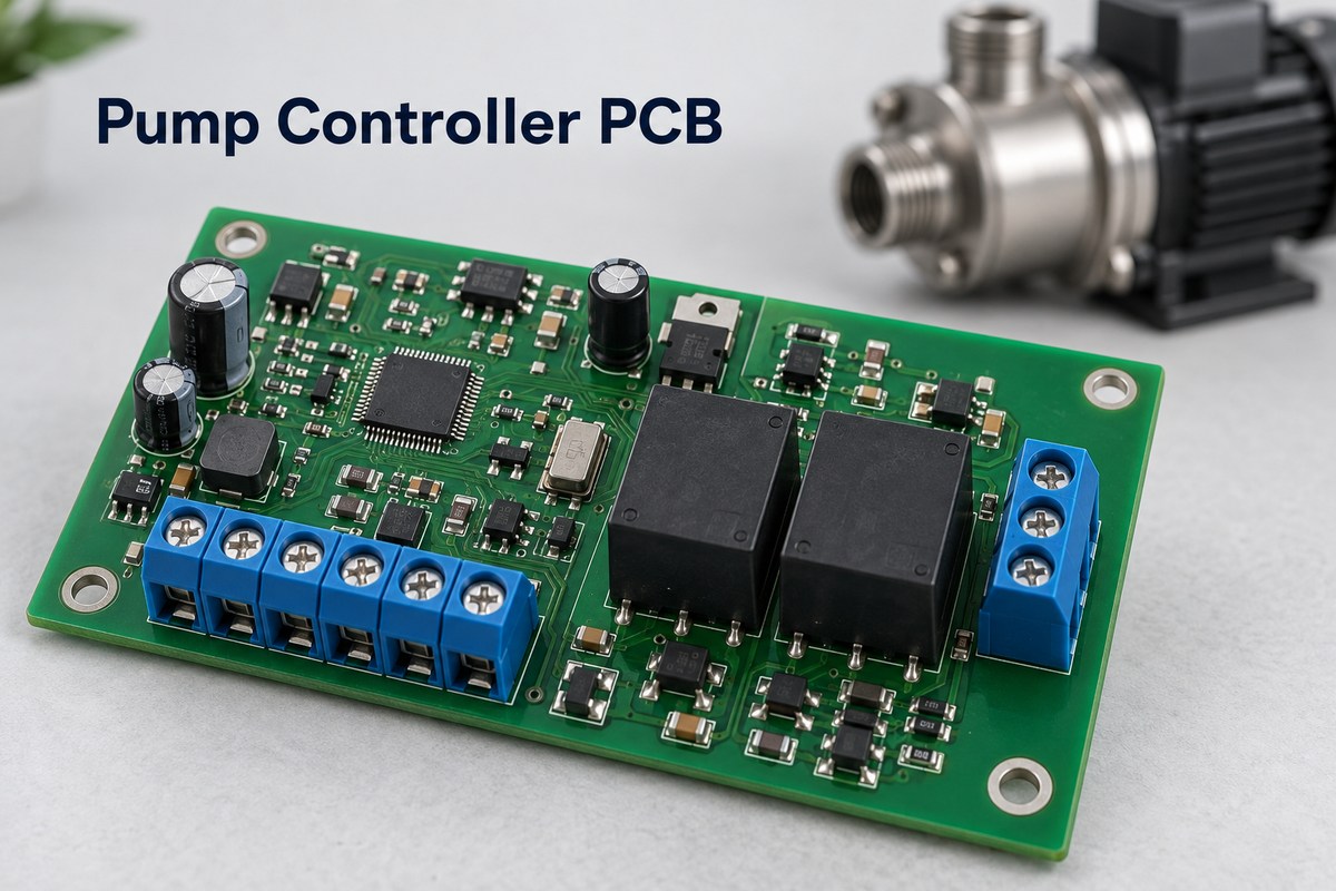
A pump controller PCB receives operating signals and controls when a water pump starts, stops, or changes speed. Its role depends on the system: a tank-filling controller responds to water level, a pressure booster responds to demand, and a variable-speed pump may need a power stage as well as control logic. These boards share a purpose, but they are not interchangeable.
For a pump-control assembly, reliable production involves both the low-voltage signal circuitry and the connections that carry or switch power. EBest Circuit supports PCB fabrication, component sourcing, assembly, inspection, and agreed functional testing from customer-approved designs. To discuss a pump controller PCB build, contact sales@bestpcbs.com.
What Does a Pump Controller PCB Control?
The board turns operating inputs into pump commands. Depending on its design, those commands may switch a relay, energize an external contactor, or set the speed of a motor drive.
Pressure, level, or flow input → control logic → switching or drive command → pump response
Feedback closes this loop. For example, a filling system can start a pump at a low tank level and stop it at a high level. An alarm input may override the normal command when a monitored fault occurs.
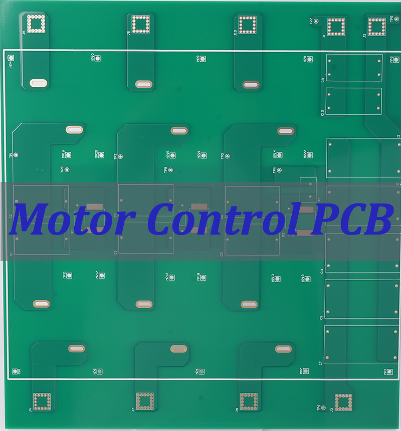
The PCB is the bare board; the PCBA includes its mounted components. A complete controller may also include firmware, terminals, a display, and an enclosure. Some control boards only send signals to a separate power unit. Others integrate a motor control PCB function and carry motor current through onboard switching devices.
How Do On/Off and Variable-Speed Pump Controllers Differ?
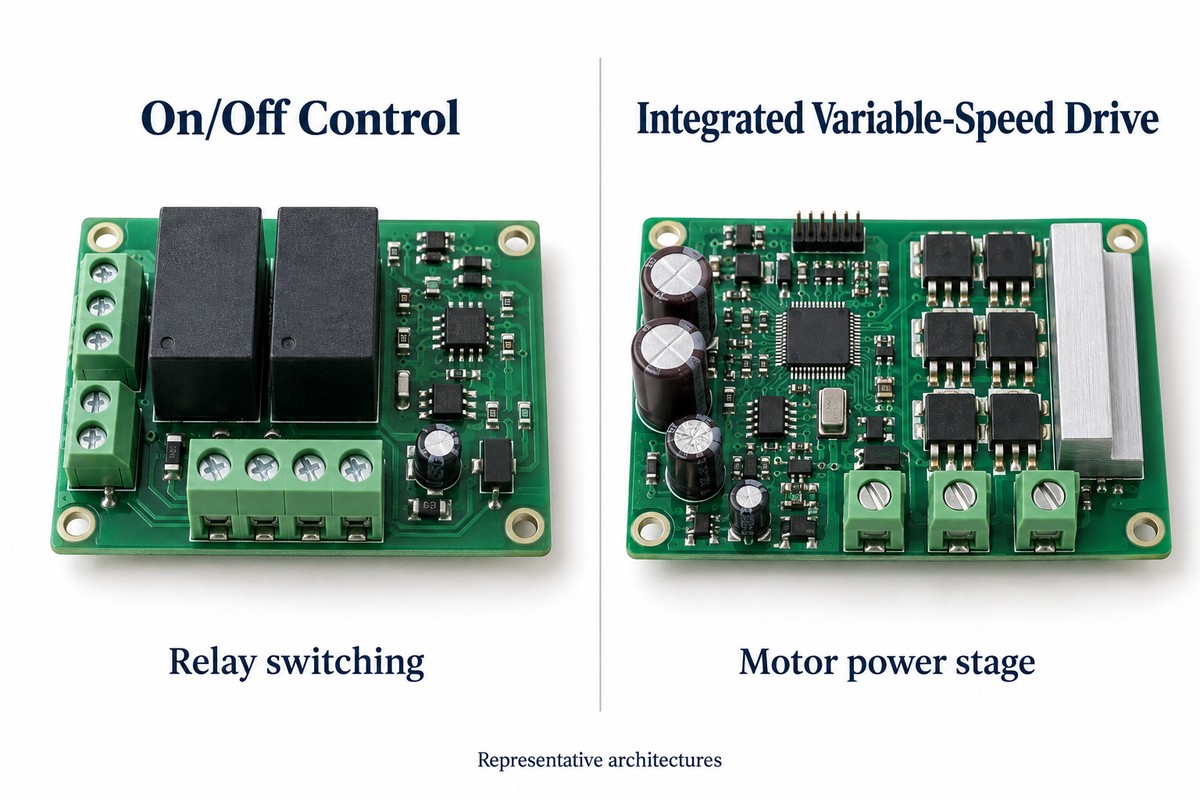
On/off control changes whether a pump runs; variable-speed control changes how fast it runs. This difference changes both the control method and the power electronics.
| Control type | Board output | Pump behavior |
|---|---|---|
| On/off control | A relay or control signal switches the pump supply or an external contactor. | The pump starts and stops as operating thresholds are reached. |
| Variable-speed control | A speed command goes to a separate drive, or an onboard power stage drives a compatible motor. | The system adjusts speed within its operating range to follow demand. |
A controller with a speed-setting input does not necessarily contain the motor power stage. Conversely, a low-voltage brushless pump assembly may combine sensing, control, and three-phase switching on one board.
Variable-speed control can help regulate pressure as demand changes, but it requires a compatible pump and motor-drive system. Adding a PWM output to an on/off controller does not make an ordinary fixed-speed pump suitable for variable-speed operation.
How Do Pressure, Level, and Flow Signals Affect Pump Operation?
Each signal describes a different part of the water system. A controller may use one signal for normal operation and another to detect an abnormal condition.
- Pressure: Indicates system pressure. A pressure drop can trigger a booster pump; a pressure-feedback loop can also adjust speed.
- Level: Indicates how much water is available or stored. Low and high levels can define a filling or draining cycle.
- Flow: Indicates water movement. It can help distinguish an active demand from a condition in which the motor runs but water is not being delivered.
The input circuit must match the sensor interface. A float switch provides a switching state; a transmitter may provide an analog signal such as 4–20 mA. These inputs need different conditioning and cannot be substituted simply because both measure a water-system condition.
The same level signal can produce opposite actions. A low level may start a tank-filling pump, while a low source-water level may stop it to prevent dry running.
How Does a Pump Controller Detect Dry Running and Motor Overload?
Dry-running protection detects insufficient water; overload protection detects excessive motor loading. One does not automatically provide the other.
| Condition | Possible detection method | Key limitation |
|---|---|---|
| Dry running | Source-level or suction-pressure monitoring; combined pressure and flow monitoring; a suitable motor-load detection method. | The method must suit the pump. Loss of water does not necessarily cause high current. |
| Motor overload or stall | Current monitoring, thermal protection, or driver fault detection. | Thresholds and timing must distinguish a fault from permitted starting behavior. |
Some pump systems infer loss of water from reduced motor load. Others use a dedicated level switch or evaluate pressure and flow together. A current sensor alone does not establish that a board has effective dry-running protection.
After detection, the controller may stop the pump, signal an alarm, and either wait for a manual reset or follow a defined restart sequence. The restart behavior is part of the protection design; repeated attempts without restored water availability can keep exposing the pump to the original problem.
Why Does a Pump Start and Stop Too Frequently?
Frequent cycling can originate in the water system, the control settings, or the feedback signal. Replacing the PCB will not correct a leak or restore a pressure tank’s lost precharge.
- Pressure falls after shutdown: A leak or water returning through an ineffective check valve can repeatedly create a new start demand.
- Very little water is drawn between starts: In a system using a pressure tank, tank condition, sizing, and precharge can affect cycling.
- Start and stop thresholds are close: Small changes in pressure or level may repeatedly cross both thresholds.
- The reported signal fluctuates: Sensor noise or an unstable connection can create switching commands that do not reflect actual demand.
Separate start and stop thresholds provide hysteresis: the pump does not change state at one identical boundary in both directions. Filtering or timing logic may also suppress brief disturbances, where the application permits it. These measures cannot replace a required fault response or repair a hydraulic problem.
How Can Motor Switching Disrupt Pump Controller Signals?
Switching currents can disturb the supply and reference voltages used by the controller. A board may read its sensors correctly while idle, then show unstable readings or reset when the motor starts.
Motor-drive switching loops, relay circuits, and long external wiring can couple disturbances into nearby signal paths. If a sensitive input shares an unsuitable return path with a pulsed power current, the input’s reference can move even when the sensor output has not changed.
Relevant PCB layout measures include:
- Keeping high-current switching loops compact and away from sensitive input routing.
- Placing decoupling and driver components close to the pins they support.
- Routing current-sense connections separately from load-current paths where the sensing arrangement requires it.
- Providing controlled return paths and appropriate filtering or protection at external interfaces.
Ground-plane splits are not a universal solution; a split can force signal return current onto a longer path. Layout should follow the selected driver and interface requirements. Functional testing should include switching activity and representative inputs, rather than only checking that the board powers on.
How Do Moisture and Condensation Affect Pump Controller PCBs?
Moisture can reduce surface insulation and contribute to corrosion. Contamination on the board can make the effect worse, producing leakage currents or intermittent behavior before visible damage appears.
A controller can encounter condensation inside its housing even without direct splashing. Protection therefore involves the assembly surface as well as the enclosure.
- Conformal coating: Protects covered surfaces, but performance depends on cleanliness, coverage, cure, and material suitability.
- Potting: Surrounds the assembly with a larger volume of protective material. Material choice affects heat transfer, mechanical stress, and repairability.
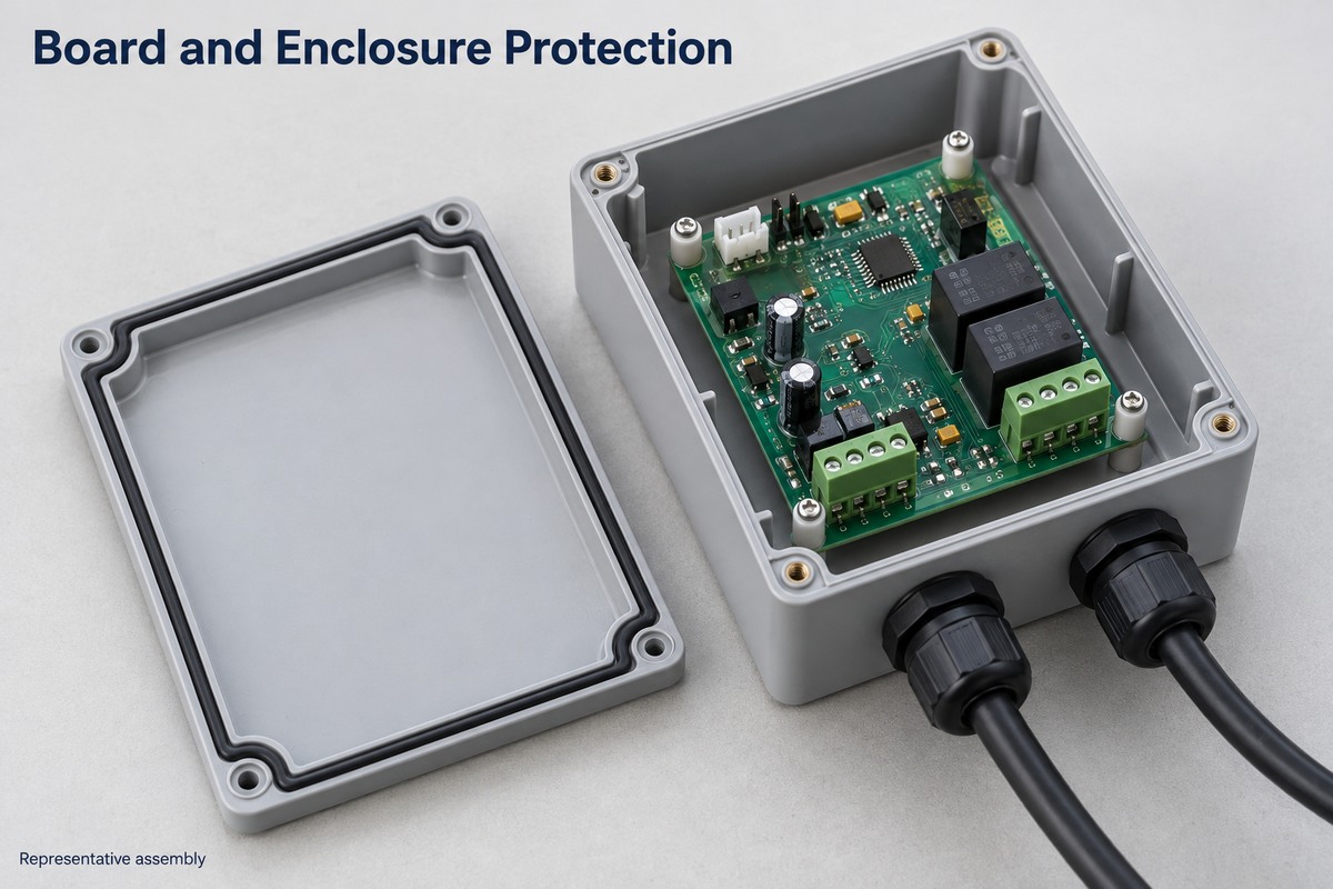
- Enclosure protection: Addresses exposure through the housing and cable entries. A coated board alone does not establish an enclosure’s waterproof rating.
Connector contacts, test points, and other designated areas may need to remain uncoated. The finished assembly needs evaluation under its intended environmental conditions; applying a protective layer is not, by itself, proof of long-term moisture resistance.
FAQs About Pump Controller PCBs
Can one pump controller PCB operate different pumps?
Only within its supported electrical and control range. Motor type, starting current, output stage, sensor interfaces, and control settings all affect compatibility.
Is matching the supply voltage enough when replacing a board?
No. Connector pinouts, motor outputs, sensor inputs, firmware, and protection behavior also need to match. Two boards with the same voltage rating can perform different functions.
Does every pump controller PCB need firmware?
No. Some simple controllers use analog or fixed logic circuits. A microcontroller-based board needs suitable firmware, while some motor-control ICs use configurable built-in functions.
Does a successful power-on test prove the controller works?
No. It does not demonstrate correct sensor response, pump commands, or fault handling. The agreed test scope should exercise those functions with suitable input simulation and loads.
What is the difference between ordering a bare PCB and a PCBA?
A bare PCB provides the circuit’s physical interconnections. A PCBA includes assembled components; programming and functional testing are additional operations that must be included in the manufacturing scope when required.
For a pump controller PCB project, EBest Circuit can review the approved board data and assembly requirements, with particular attention to power connections, sensor interfaces, and the agreed test sequence. Discuss your build with sales@bestpcbs.com.
You may also like



Tags: Motor Control PCB, Pump Controller PCB, Water Pump Control