





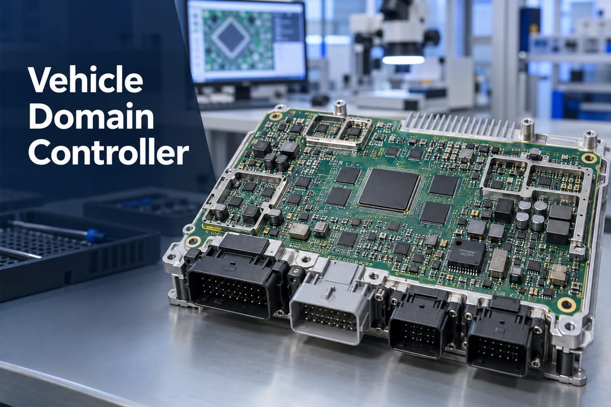
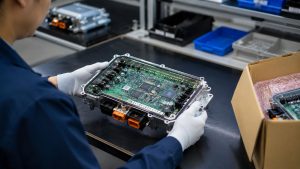
A vehicle domain controller combines the processing, communication, and control resources that were previously distributed across several automotive ECUs. Its PCBA may carry a high-performance processor, high-speed memory, vehicle-network interfaces, power-management circuits, security devices, storage, and large harness connectors on one densely populated board. Manufacturing that assembly requires more than placing components correctly; the soldering process must accommodate fine-pitch packages, uneven thermal mass, hidden joints, and strict mechanical constraints at the same time.
EBest Circuit (Best Technology) supports customer-released domain-controller projects through an IATF 16949-certified automotive quality-management system. Our capabilities include multilayer and HDI PCB fabrication, controlled-impedance manufacturing, component sourcing, mixed SMT and through-hole assembly, AOI, X-ray inspection, programming coordination, MES-based traceability, and customer-defined testing. These controls help keep the correct hardware revision, component identity, process records, and approved manufacturing route connected as a project moves from prototypes to repeat production. To discuss a domain controller PCBA build, send the released PCB data, BOM, assembly information, quantities, and required test scope to sales@bestpcbs.com.
What Is a Vehicle Domain Controller?
A vehicle domain controller is a high-performance electronic control unit that manages several related functions within one vehicle domain. Instead of assigning every function to a separate ECU, the controller provides shared computing, communication, power-management, and software resources for a group of systems.
The “domain” describes a logical group of vehicle functions. Depending on the vehicle architecture, it may cover body and comfort systems, the digital cockpit, ADAS, propulsion, chassis, connectivity, or a combination of these areas.
A domain controller is therefore not simply a larger version of a conventional ECU. It must receive data from many sensors and network nodes, process multiple workloads, exchange information with other controllers, and maintain predictable operation when one function places a heavy demand on shared hardware.
It should also be distinguished from a zone controller. A domain controller groups functions by purpose, while a zone controller usually groups physical inputs, outputs, sensors, and actuators by their location in the vehicle. Some newer platforms use both: zone controllers collect local signals, and a domain or central computer performs higher-level processing.
How Does Automotive Domain Controller Architecture Consolidate ECUs?
Automotive domain controller architecture consolidates ECUs by moving compatible workloads onto shared processing and communication hardware. The goal is not to connect several existing ECUs inside one enclosure. It is to reduce duplicated processors, memory, power supplies, gateways, and network interfaces while coordinating the functions through a common computing platform.
For example, several cockpit functions may share an applications processor, graphics resources, memory, storage, and vehicle-network connection. An ADAS domain controller may receive camera, radar, and other sensor data through high-speed interfaces, process the information, and exchange decisions with braking, steering, or gateway controllers.
This consolidation changes the PCBA in several ways:
- processor and memory density increases;
- high-speed interfaces occupy more routing and connector resources;
- several supply rails must start, sequence, and remain stable under changing loads;
- communication traffic from CAN, CAN FD, LIN, Automotive Ethernet, or other interfaces converges on one assembly;
- thermal load becomes concentrated around processors, memory, PMICs, and network devices;
- a defect in one shared resource can affect several vehicle functions.
The architecture can reduce module count and wiring complexity, but it also concentrates electrical, thermal, and manufacturing risk. That is why a domain-controller PCBA cannot be treated as a generic control board with a faster processor added.
Which Functions Can an Automotive Domain Controller Combine?
An automotive domain controller combines functions that need shared computing, coordinated data, or common vehicle interfaces. The exact grouping depends on the automaker's electrical and electronic architecture; there is no universal set of functions for every controller.
Common domain groupings include:
- Body domain: lighting, doors, windows, seats, mirrors, wipers, access, and comfort functions.
- Cockpit domain: digital instrument clusters, infotainment, displays, audio, voice processing, and driver interaction.
- ADAS domain: sensor input, image or radar processing, sensor fusion, path-related calculations, and communication with actuation controllers.
- Propulsion domain: engine, transmission, inverter, motor, battery, charging, and energy-management coordination.
- Connectivity domain: external wireless connectivity, gateways, secure data exchange, over-the-air service support, and communication between internal and external networks.
These categories can overlap. A cockpit controller may include connectivity functions, while a central vehicle computer may run workloads from more than one traditional domain. The released system architecture—not the marketing name—determines what the PCBA must support.
This distinction also keeps closely related modules separate. A body control module mainly controls body loads and convenience functions. A telematics control unit focuses on vehicle-to-network communication. A domain controller may coordinate either area, but its defining feature is the consolidation of multiple related workloads and interfaces.
What Hardware Is Inside a Vehicle Domain Control Unit?
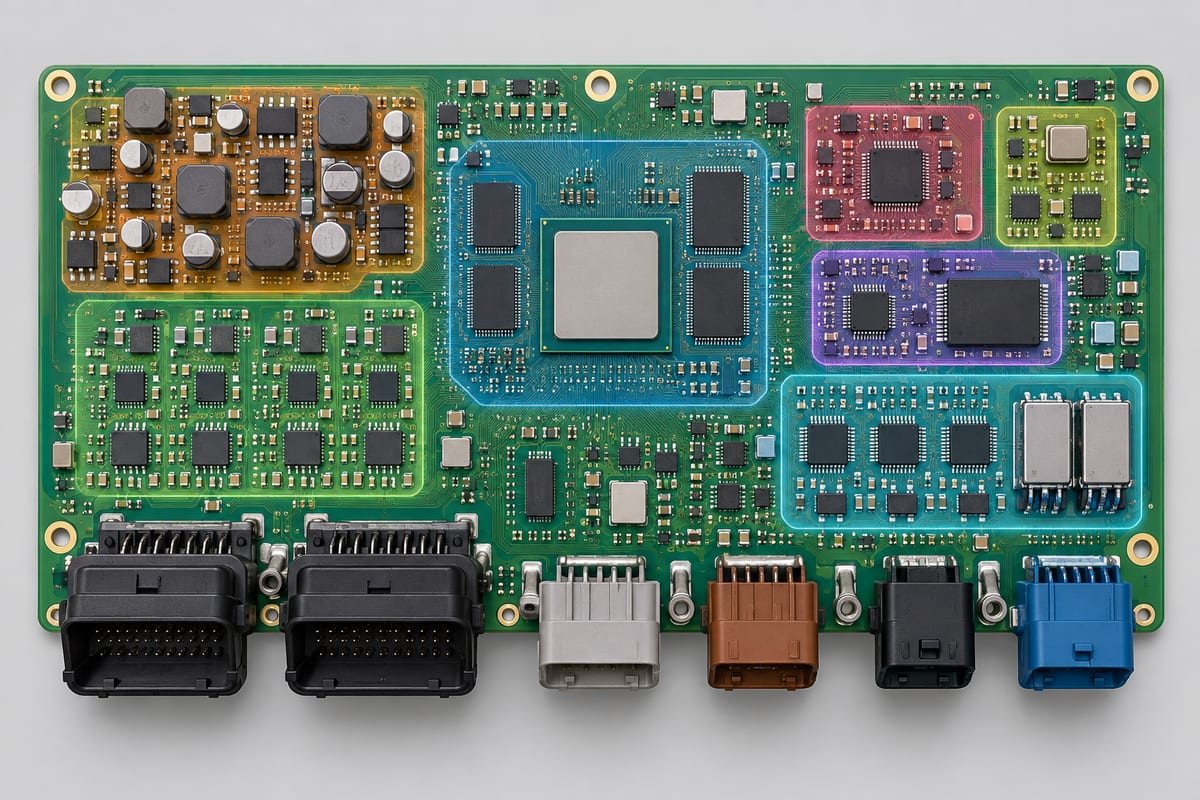
The hardware inside a vehicle domain control unit reflects the functions it consolidates. A body-domain board may emphasize protected inputs and load drivers, while an ADAS or cockpit controller may emphasize computing performance, memory bandwidth, high-speed networking, and thermal management.
Typical hardware blocks include:
| Hardware block | Typical devices | Manufacturing concern |
|---|---|---|
| Main processing | Automotive MCU, MPU, SoC, FPGA or accelerator | Fine-pitch BGA assembly, heat and lifecycle control |
| Memory | LPDDR, DDR, Flash, eMMC or UFS | Short high-speed connections and hidden solder joints |
| Vehicle networking | CAN, CAN FD, LIN, FlexRay and Automotive Ethernet devices | Controlled-impedance paths, termination and connector transitions |
| Power management | PMICs, DC-DC converters, LDOs, supervisors and protection devices | Multiple rails, switching heat and package-specific soldering |
| Storage and security | Secure elements, hardware security modules and nonvolatile storage | Programming, identification and configuration control |
| Sensor or display interfaces | SerDes, camera links, display interfaces and level translation | High-speed differential routing and connector integrity |
| Timing | Crystals, oscillators, clock generators and buffers | Placement sensitivity and contamination control |
| External connection | Board-to-board and harness connectors, coaxial or high-speed connectors | Mechanical load, coplanarity and through-hole soldering |
The board may also include shielding frames, heatsink contact areas, thermal interface material, mounting points, test pads, and service or programming connectors. These mechanical features influence component placement and assembly sequence even though they are not active electronic functions.
Compared with a conventional electronic control unit board, a high-performance domain controller usually places greater pressure on routing density, package pitch, memory proximity, power distribution, and heat removal.
What Makes a Domain Controller PCBA Difficult to Assemble?
A domain controller PCBA is difficult to assemble because it combines components that need very different soldering conditions on the same board. A fine-pitch BGA needs controlled solder-paste deposition, board support, package alignment, and a stable reflow profile. When solder paste inspection is included in the production route, it can identify deposit-volume or alignment problems before those conditions become hidden beneath a BGA after reflow. A large connector, shield frame, inductor, or power component absorbs much more heat and may require a different assembly process.
The main difficulty is the interaction between these requirements, not any one component by itself.
Typical assembly conflicts include:
- small passives and fine-pitch packages beside tall connectors or shielding structures;
- high-density BGA regions with limited optical access;
- large ground planes that draw heat away from selected joints;
- heavy connectors that need strong solder joints without overheating nearby components;
- bottom-terminated packages whose solder coverage cannot be judged by surface appearance;
- components with moisture-sensitivity or storage requirements that differ from the rest of the BOM;
- heatsink, shield, coating, or enclosure steps that can obstruct later inspection or rework.
Process sequencing matters. Shield frames or large connectors installed too early may block X-ray views, rework access, or test fixtures. Installed too late, they may require an additional heating process that exposes the board to more thermal stress. The assembly plan therefore has to follow the actual package mix, board construction, thermal mass, and inspection access.
That process plan also has to survive the transition from prototypes to repeat production. Recording the approved stencil, placement program, reflow profile, fixtures, inspection settings, and product revision helps prevent a later batch from being built with an outdated or incomplete process. MES-based traceability can connect those records with the applicable PCB, component lots, and programmed product identity.
Domain controllers also contain costly processors and memory devices. Soldering a visible connector correctly does not compensate for an open BGA joint beneath the main processor. Inspection and process control must therefore follow the failure modes of each package rather than rely on one final visual check.
How Are High-Pin-Count BGAs and Automotive Connectors Assembled on One PCBA?
High-pin-count BGAs and automotive connectors can share one PCBA when the assembly sequence, board support, solder volumes, and thermal profile are planned for both package types. The challenge is that they sit at opposite ends of the assembly spectrum: the BGA depends on uniform hidden joints, while the connector must withstand insertion force, harness load, and repeated temperature and vibration exposure.
For the BGA area, solder-paste printing must produce repeatable deposits on adjacent fine-pitch components. Placement accuracy and package handling are important, but the reflow profile is equally critical. The board must reach sufficient temperature for complete solder formation without creating excessive package warpage, voiding, component damage, or unnecessary thermal exposure.
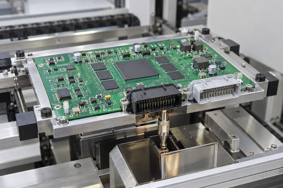
Large automotive connectors may use surface-mount hold-downs, press-fit pins, through-hole solder joints, or a combination of retention features. Through-hole pins can be assembled by selective soldering, pin-in-paste, or another approved process depending on connector geometry, board thickness, nearby components, and solder-side access.
Several practical interactions must be resolved:
- The connector body must not shadow nearby components during reflow or block the selective-soldering nozzle.
- Through-hole copper connected to large planes may need more heat than signal pins in the same connector.
- Board supports must prevent the connector's mass or insertion load from flexing the BGA region.
- Pin protrusion, hole fill, solder bridging, and connector seating must all remain within the released acceptance criteria.
- X-ray access to the processor, memory, and other hidden joints should remain usable after the connector and shielding hardware are installed.
The best process is not automatically “reflow everything” or “solder the connector later.” It is the sequence that creates a stable window for both the hidden BGA joints and the mechanically loaded connector joints on the actual board. EBest Circuit's mixed-assembly experience allows the BGA, surface-mount hold-downs, through-hole pins, shielding hardware, and inspection access to be reviewed as one manufacturing sequence rather than as unrelated operations.
How Do Heat and Board Warpage Affect Domain Controller Assembly?
Heat and board warpage affect domain controller assembly by changing how packages, pads, and solder joints meet during reflow. A dense processor region, thick copper planes, large connectors, and uneven component distribution can create substantial temperature differences across the PCBA. At the same time, the PCB and large packages expand at different rates.
If a BGA package or the PCB bows during reflow, corner balls may separate from their pads or touch only after part of the solder has solidified. This can create opens, head-in-pillow defects, stretched joints, or weak connections that are difficult to see from the surface. Excessive board deformation can also affect fine-pitch connectors, bottom-terminated packages, and coplanarity during later assembly steps.
Production controls should address the actual thermal and mechanical behavior:
- support the panel and assembly near heavy or mechanically sensitive regions;
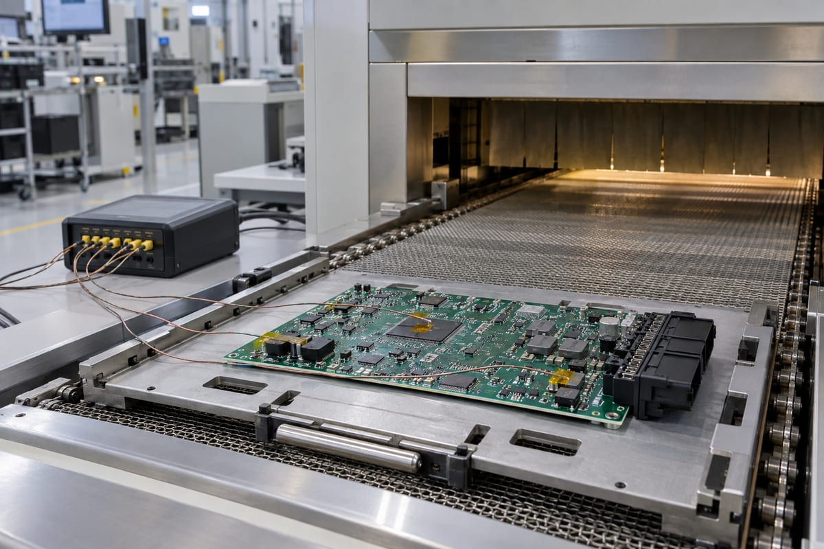
- profile representative boards at both high-mass and low-mass locations;
- keep the time and peak temperature within the limits of the PCB, packages, solder alloy, and moisture-sensitive devices;
- review copper balance, board thickness, panel rails, breakaway features, and component distribution for their effect on deformation;
- use package-appropriate X-ray views to assess hidden joints after soldering;
- avoid fixture pressure that masks or introduces board bending during inspection and test;
- control heatsink and enclosure attachment forces so that the finished board is not flexed around large BGAs.
Thermal performance in use and soldering temperature during production are related but different problems. A copper area or thermal path that helps cool the operating processor can increase local thermal mass during reflow. The assembly process must therefore be developed from the released board construction and component layout rather than from a generic oven recipe.
FAQs About the Vehicle Domain Controller
Is a vehicle domain controller the same as an ECU?
A vehicle domain controller is a type of high-performance ECU. A conventional ECU may control one function or subsystem, while a domain controller consolidates several related functions, networks, or workloads on shared hardware.
What is the difference between a domain controller and a zone controller?
A domain controller groups functions by purpose, such as cockpit, ADAS, body, or propulsion. A zone controller groups sensors, actuators, power distribution, and network connections by physical vehicle location. A vehicle architecture may use both.
Does every vehicle domain controller use an HDI PCB?
No. HDI becomes useful when processor fan-out, memory routing, package pitch, interface count, or board-size limits cannot be handled reliably with conventional through-hole vias. The released component placement, stackup, routing density, and manufacturing limits determine whether HDI is necessary.
Why are BGAs common in domain controller PCBAs?
High-performance processors, memory, FPGAs, and network devices need many power, ground, and signal connections in a compact area. BGA packages provide high connection density and short electrical paths, but their joints are hidden and require a controlled assembly and inspection process.
Can a PCBA manufacturer build the complete vehicle domain controller?
A PCBA manufacturer can fabricate the released PCB, source approved components, assemble the board, inspect hidden and visible joints, program devices, and perform agreed electrical or functional tests. The exact deliverable depends on the released product data and quotation scope.
A reliable vehicle domain controller PCBA depends on managing several difficult features together: dense processors and memory, controlled-impedance networks, multiple power rails, heavy automotive connectors, hidden solder joints, and concentrated heat. EBest Circuit combines IATF 16949 process control with multilayer and HDI fabrication, mixed assembly, AOI, X-ray inspection, MES-based traceability, programming coordination, and customer-defined testing. When required by the confirmed project scope, automotive documentation such as PPAP-related records can also be coordinated without confusing manufacturing evidence with vehicle-level validation.
For a vehicle domain controller program, this combination helps preserve the approved product revision and manufacturing process as the build moves from prototypes to repeat production. Send your released PCB data, BOM, assembly information, quantities, and required test scope to sales@bestpcbs.com for review.
You may also like
Tags: Automotive Domain Controller Architecture, Domain Controller PCBA, Vehicle Domain Controller