PCB manufacturing PCB manufacturing
Home > Blog

What is the IPC-6018 Standard? IPC 6012 vs IPC-6018

May 18th, 2026

Does IPC-6018 matter when a high frequency PCB already uses controlled impedance and RF material? Yes. RF and microwave PCBs still need clear rules for material control, fabrication quality, testing, and final acceptance. Small changes in dielectric thickness, copper roughness, via quality, annular ring, or layer registration can affect impedance and signal loss. This article explains IPC 6018, its performance grades, applications, technical requirements, difference from IPC 6012, latest version, official PDF source, and common questions.

IPC-6018, https://www.bestpcbs.com/blog/2026/05/ipc-6018/

What is the IPC-6018 Standard?

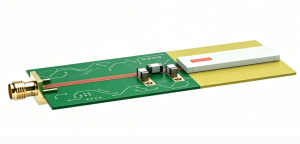
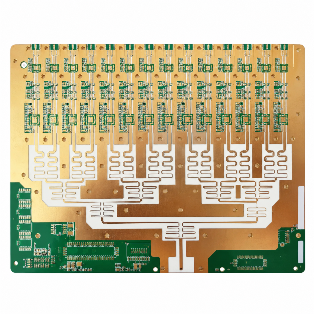
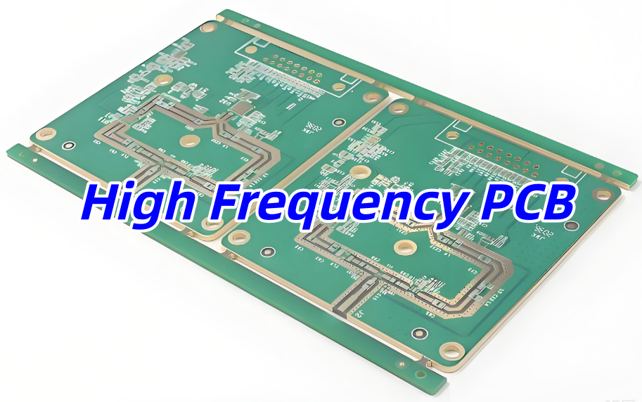
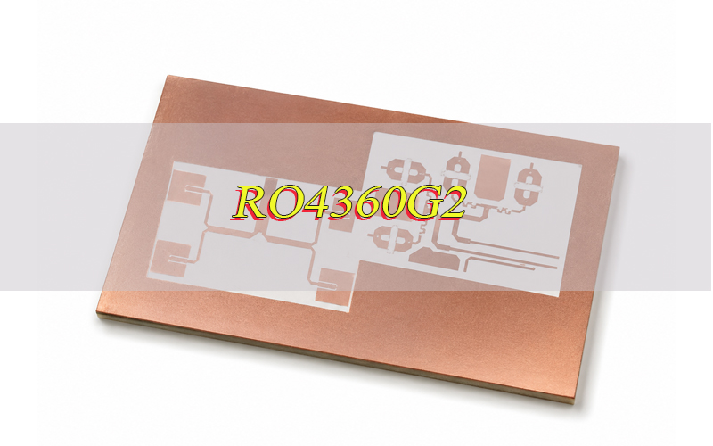
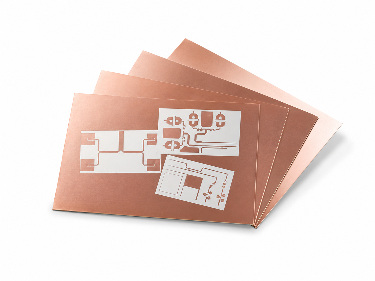
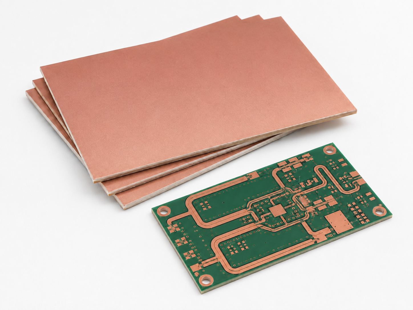
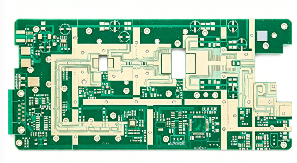
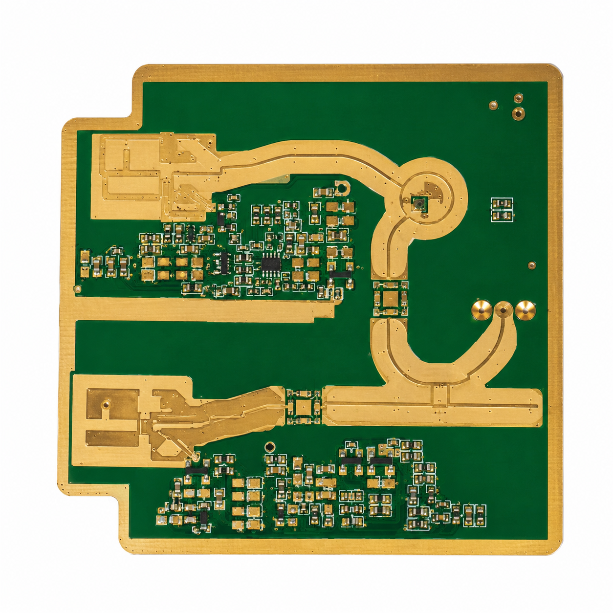
IPC-6018 is a performance specification for high frequency microwave printed boards. It defines the quality and acceptance requirements for RF and microwave PCBs used in applications where signal stability, impedance control, and reliable fabrication are important.

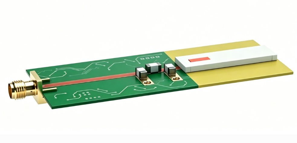
IPC 6018 is commonly used for boards with microstrip, stripline, controlled impedance traces, multilayer RF structures, blind vias, buried vias, and metal core designs. It helps designers, buyers, and PCB manufacturers confirm the same requirements before production.

For high frequency PCBs, small changes in material thickness, copper quality, via plating, or layer alignment can affect electrical performance. Therefore, IPC 6018 gives a clear reference for fabrication quality, inspection, testing, and final acceptance.

In simple terms, IPC 6018 helps make sure a high frequency PCB is not only manufactured correctly, but also reliable for its intended RF or microwave application.

What are the Performance Grades of IPC 6018?

IPC 6018 uses performance classes to define how reliable and strictly controlled a high frequency PCB should be. The right class depends on the product use, working environment, reliability risk, and cost target.

  • IPC 6018 Class 1: Class 1 is used for basic products with limited service life. It is rarely used for demanding RF or microwave PCBs.
  • IPC 6018 Class 2: IPC 6018 class 2 is common for commercial RF boards, such as antenna boards, wireless modules, communication devices, RF test boards, and general microwave circuits.
  • IPC 6018 6018 Class 3: IPC 6018 class 3 is used for boards that need stronger reliability, tighter fabrication control, and better inspection records. It is suitable for aerospace, radar, satellite communication, defense electronics, medical RF devices, and high value instruments.
  • IPC 6018 class 3a and IPC-6018DS: IPC 6018 class 3a is often searched for space, military, or avionics RF boards. In current projects, these applications should review IPC-6018DS, which is used together with IPC-6018D for stricter space and military avionics requirements.

What Are Appliactions of IPC-6018?

IPC 6018 is used when electrical performance is sensitive to material, geometry, plating, registration, and processing control. It is not only an inspection document. It is also a purchasing and communication tool between design, fabrication, quality, and supply chain teams.

  • RF and microwave communication boards: Base station modules, filters, amplifiers, couplers, antenna boards, phased array structures, and wireless infrastructure.
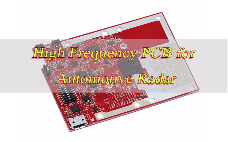
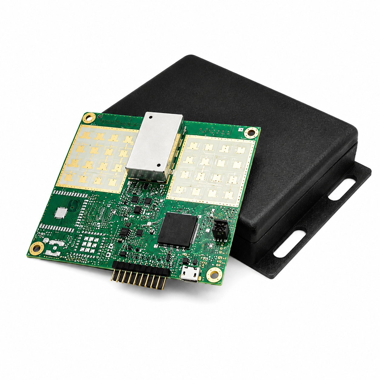
  • Radar and sensing electronics: Automotive radar, industrial radar, defense radar, collision sensing, and microwave detection modules.
  • Aerospace and avionics boards: High reliability RF boards may require Class 3 or IPC-6018DS requirements for severe vibration, ground testing, and thermal cycling environments.
  • Satellite and space communication systems: For IPC-6018 space applications, the drawing should clearly call out the base document, addendum, class, laminate, copper, finish, impedance, test coupon, and traceability requirements.
  • Medical RF devices: Imaging, diagnostic, RF therapy, and wireless medical modules where repeatable performance and clean documentation matter.
  • High speed test and measurement equipment: RF test boards, calibration modules, probe interface boards, microwave fixtures, and signal integrity validation boards.

What are Technical Requirements for IPC 6018?

IPC 6018 technical requirements focus on whether the fabricated board can meet its intended RF, microwave, mechanical, and reliability performance. For high frequency PCBs, small process variations can affect signal behavior. Therefore, the fabrication drawing should clearly define the standard, class, material, stackup, finish, test method, and acceptance criteria before production. Below is a table of technical requirements for IPC 6018 for your reference:

ItemSpecification
Board TypesSingle/double-sided, multilayer (with/without blind/buried vias), metal core, HDI, embedded components
Performance ClassesClass 1 (General), 2 (Dedicated), 3 (High-Reliability)
Dielectric Constant (Dk)Low & stable (e.g., PTFE, ceramic-filled); controlled tolerance (±0.5 @ 10 GHz typical)
Dissipation Factor (Df)Low loss: ≀0.001–0.003 @ 10 GHz (material-dependent)
Thermal StabilityTg ≄ 180°C; low Z-axis expansion (≀2.5% @ 260°C)
Dimensional Stability±0.001 mm/mm after environmental exposure
Foil TypeType E3 (HTE) per IPC-4562; purity ≄99.9%Global Electronics Association
Surface RoughnessRz ≀ 2 ÎŒm (low loss for high frequency)
Thickness ToleranceSurface: ±10% of nominal; PTH/via: min 20 Όm (Class 3)
Plating IntegrityNo voids, cracks, or overhang; copper cap for filled holes
Tolerance±5% (Class 3, microwave); ±10% (Class 2)
Feature ControlLine width/space: ±8% deviation max
Dielectric Thickness±5% of nominal; no reduction >10%
PTH Copper ThicknessMin 25 ÎŒm (Class 3); min 20 ÎŒm (Class 2)
Microvia (Blind/Buried)Min copper 15 ÎŒm; no pad cratering
Annular RingMin 0.1 mm (Class 3); min 0.05 mm (Class 2)
Back-Drilled HolesControlled depth; no residual copper stub
Final CoatingsImmersion Ag, Au, Sn; OSP; solder mask (per Table 3-3)
Solder MaskThickness 25–50 ÎŒm; no coverage on RF pads/transmission lines
Insertion LossMax 0.5 dB/in @ 10 GHz (material & design dependent)
Return Loss≄20 dB (VSWR ≀1.22) for microwave circuits
Isolation≄30 dB between adjacent transmission lines
Dimensional ToleranceOverall: ±0.1 mm; feature: ±0.05 mm
Warpage≀0.5% (Class 3); ≀1.0% (Class 2)
Edge QualityNo delamination; max burr 0.05 mm
Thermal Cycling-55°C to +125°C; 1000 cycles (Class 3)Global Electronics Association
Humidity Resistance85°C/85% RH; 500 hours; no electrical/mechanical failure
Vibration/ShockMIL-STD-810 compliant (aero/space)Global Electronics Association
Acceptance TestingVisual, dimensional, electrical, environmental per IPC-6018D
ConformanceLot traceability; material COC; impedance/loss test recordsGlobal Electronics Association

What is the Difference Between IPC 6012 and IPC-6018?

IPC 6012 and IPC 6018 are both performance specifications for printed boards, but they are not used for the same board category. The simple answer is this: IPC 6012 is for rigid printed boards in general, while IPC 6018 is for high frequency microwave printed boards.

ItemIPC 6012IPC 6018
Primary ScopeRigid printed boardsHigh frequency microwave printed boards
Common Board TypeFR4 rigid PCB, multilayer rigid PCB, HDI rigid PCBRF PCB, microwave PCB, mixed dielectric RF PCB
Main Control FocusStructural reliability, plating, holes, conductors, acceptanceRF performance plus structural reliability
Material FocusGeneral rigid PCB materialsLow loss RF laminates, PTFE based materials, ceramic filled materials, mixed dielectric builds
Impedance ConcernOften required for high speed digital boardsUsually central to the design
Typical UseIndustrial control, power electronics, medical electronics, consumer electronicsRF modules, radar, antennas, microwave communication, aerospace RF
Drawing CalloutBuild and inspect to IPC 6012 Class 2 or Class 3Build and inspect to IPC 6018 Class 2 or Class 3
When to UseStandard rigid PCB performance acceptanceRF and microwave board performance acceptance
IPC-6018, https://www.bestpcbs.com/blog/2026/05/ipc-6018/

A common mistake is specifying IPC 6012 for a complex RF board simply because the board is rigid. That may leave gaps in microwave related acceptance requirements. For a Rogers mixed dielectric multilayer RF board, IPC 6018 is usually the more suitable base standard.

What is the Latest Version of IPC-6018?

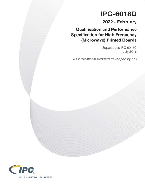
The IPC-6018 latest version question should be checked through IPC or authorized standards distributors before releasing a fabrication drawing. As of the latest source check, IPC-6018D is listed as the current Revision D document for “Qualification and Performance Specification for High Frequency Microwave Printed Boards.” The official IPC shop page lists IPC-6018D, Revision D, Standard Only, in English.

The related space and military avionics addendum is IPC-6018DS, dated August 2022. IPC states that the addendum supplements or replaces specifically identified requirements of IPC-6018D for high frequency microwave printed boards that must survive vibration, ground testing, and thermal cyclic environments of space and military avionics.

The difference between the two documents is important:

  • IPC-6018D is the base specification.
  • IPC-6018DS is an addendum for space and military avionics applications. It should be used with the base document when procurement documentation requires it.
IPC-6018, https://www.bestpcbs.com/blog/2026/05/ipc-6018/

For new drawings, avoid vague notes such as “meet IPC standard.” A better note states the exact document, class, addendum if required, material, impedance tolerance, acceptance test, and record requirements.

Where Can You Find the Official Document of IPC 6018 PDF?

The official document should be purchased or accessed through IPC or authorized standards channels. Free copies found on random websites may be outdated, incomplete, or not licensed for company use. For compliance driven projects, always use a licensed document and confirm the revision before releasing a purchase order.

https://www.bestpcbs.com/blog/2026/05/ipc-6018/

FAQs About IPC-6018 Standard

Q1: When should a project specify IPC 6018 instead of a normal PCB fabrication standard?
A1: IPC 6018 should be specified when the board is designed for RF, microwave, radar, antenna, satellite communication, or other high frequency functions. It is especially useful when impedance stability, insertion loss, via performance, and laminate control affect final product behavior.

Q2: Can IPC 6018 be used for a rigid PCB made with FR4?
A2: It can be used when the FR4 board is part of a high frequency microwave design and the additional requirements are meaningful. For ordinary rigid FR4 boards, IPC 6012 is usually more suitable. For RF antenna boards using FR4, the design team should confirm whether IPC 6018 adds real process control value.

Q3: What should be written on a fabrication drawing when IPC 6018 is required?
A3: A clear drawing note should include the document revision, performance class, laminate name, stackup, copper thickness, surface finish, controlled impedance values, tolerance, test coupon requirement, inspection records, and whether IPC-6018DS applies.

Q4. Does IPC 6018 automatically define the impedance value for an RF PCB?
A4. No. The standard supports performance and acceptance control, but the exact impedance values must be defined by the design documentation. The drawing should state the target impedance, tolerance, reference layer, trace geometry, and coupon method where needed.

Q5: Why do RF PCB manufacturers ask for material brand and laminate thickness before quoting?
A5: RF performance depends heavily on dielectric constant, dielectric thickness, copper profile, and loss tangent. A small material change can affect impedance and insertion loss. That is why material details should be confirmed before quotation and production.

Q6: Is ipc 6018 class 2 enough for commercial RF products?
A6: In many commercial RF projects, ipc 6018 class 2 is suitable. It is commonly used for communication modules, wireless devices, test equipment, and industrial RF products where reliable long term service is needed.

Q7: When is ipc 6018 class 3 more suitable than Class 2?
A7: IPC 6018 class 3 is more suitable for high reliability applications where failure may cause serious cost, downtime, safety risk, or mission impact. Examples include aerospace RF modules, defense radar, satellite systems, medical RF equipment, and high value instrumentation.

Q8: What does IPC-6018DS add to a high frequency PCB project?
A8: IPC-6018DS adds space and military avionics related requirements to IPC-6018D. It is used when procurement documents require stronger controls for severe environments, including vibration, ground testing, thermal cycling, and mission critical service.

Q9: Why is annular ring tolerance important in IPC 6018 Class 3 RF boards?
A9: Annular ring tolerance affects via reliability and layer to layer connection quality. In dense RF multilayer boards, poor registration can increase the risk of breakout, weak interconnection, impedance drift, and inconsistent high frequency behavior.

Q10: How can buyers reduce disputes when ordering IPC 6018 RF PCBs?
A10: Buyers should send complete Gerber files, drill files, stackup, material requirements, impedance table, IPC class, surface finish, test coupon requirements, and inspection record expectations. Clear documentation helps the manufacturer quote accurately and build consistently.

You may also like

PCB Fabrication FAQ

May 18th, 2026
PCB Fabrication FAQ

PCB Fabrication

1. What is the producible copper thickness range for your PCB boards? +
We support a finished copper thickness range from 1/2oz (18”m) minimum to 30oz (1050”m) maximum, for both inner and outer layers of heavy copper PCBs.

2. What is the maximum number of PCB layers you can manufacture? +
We can manufacture PCBs with up to 32 layers, meeting the needs of high-complexity industrial and electronic designs.

3. What is the maximum PCB panel size you can produce? +
The maximum producible PCB panel size is 610mm x 610mm.
4. What is the producible finished board thickness range and tolerance? +
  • Minimum finished board thickness: 0.15mm for 1-2 layer PCBs, 0.38mm for 4-layer PCBs
  • Board thickness tolerance: ±0.1mm for board thickness <1.0mm; ±10% of board thickness for board thickness ≄1.0mm
  • Note: The final finished board thickness includes copper thickness.

5. What is the minimum drill hole size you can produce? +
The minimum producible mechanical drill hole size is 0.1mm for standard PCB designs.

6. What PCB laminate brands do you commonly use? +
We use industry-leading PCB laminate brands including Shengyi, KB, ITEQ, and GDM, ensuring stable material quality and performance.

7. What is Tg value in PCB materials, and what Tg values can you produce? +
Tg (Glass Transition Temperature) is the temperature at which the PCB laminate transitions from a rigid glassy state to a flexible rubbery state, a key parameter for high-temperature applications.
We commonly produce boards with Tg130, Tg150, and Tg≄170, and can support high-Tg boards up to Tg260 for special high-temperature requirements.

8. What is the flame retardant rating of your PCB boards? +
Our standard FR4 PCB boards meet the UL94 V-0 flame retardant rating, the highest standard for commercial PCB materials.

9. What is solder mask, and what solder mask colors are available? +
Solder mask is a protective layer applied to the PCB surface to prevent solder bridging on non-pad areas, protect copper traces from oxidation, and provide electrical insulation.
Available solder mask colors: Green, Blue, Black, Red, White, Yellow, Purple.

10. What silk screen (legend) colors are available? +
Available silk screen (legend) colors: Green, Blue, Black, Red, White, Yellow, Purple, with white being the most commonly used for standard PCB designs.

11. What is the difference between single-ended impedance and differential impedance? +
  • Single-ended impedance: Impedance control for a single transmission line, referenced to a ground plane, typically used for single-ended signal transmission.
  • Differential impedance: Impedance control for a pair of complementary transmission lines, referenced to each other, typically used for high-speed differential signal transmission (e.g., USB, HDMI, Ethernet) to improve noise immunity and signal integrity.

12. What design file formats do you support for PCB manufacturing? +
We support standard PCB design file formats including Gerber RS-274X, ODB++, and native CAD files from Altium Designer, KiCad, and other mainstream EDA software. We can also generate Gerber files from your original design drawings upon request.

13. Do you have your own PCB manufacturing factory, or are you an OEM? +
We own and operate our own PCB manufacturing factory with full in-house production capabilities from PCB fabrication to assembly, ensuring full control over production quality, lead time, and cost. We also provide OEM services for customized PCB and PCBA projects.

14. What is your PCB manufacturing quality control process? +
We implement a full-process quality control system including incoming material inspection, in-process inspection for each production step, AOI (Automated Optical Inspection), electrical testing, and final visual inspection before shipment. All production processes comply with IPC international standards.

15. Can you produce PCBs meeting IPC Class 3 standards? What is the price difference from IPC Class 2? +
Yes, we can manufacture PCBs fully compliant with IPC Class 3 standards for high-reliability aerospace, medical, and industrial applications.
The price for IPC Class 3 PCBs is typically 15%-30% higher than IPC Class 2, due to stricter production tolerances, more rigorous inspection processes, and lower production yield.

16. Can you provide PCB mechanical structure layer design services? +
Yes, our engineering team can provide PCB mechanical structure layer design services, including board outline design, mounting hole layout, keep-out area definition, and 3D model matching for your enclosure design.

17. What payment methods do you support? Do you offer monthly credit terms? +
We support multiple payment methods including T/T bank transfer, PayPal, Western Union, and credit card payments.
Monthly credit terms are available for long-term cooperative customers with stable order volume, subject to credit review and approval.

18. Can you provide a detailed production schedule for my PCB order? +
Yes, we provide a detailed step-by-step production schedule for every order, including expected completion time for each production process, inspection stages, and final shipment date. We also provide real-time production progress updates upon request.

You may also like

PCB Layout FAQ

May 18th, 2026
PCB Layout FAQ

PCB Layout

1. What impedance control capabilities do you support for PCB designs? +
We support full impedance control for PCB designs, including single-ended impedance (typically 50Ω, 75Ω) and differential impedance (typically 90Ω, 100Ω, 120Ω), with an impedance control tolerance of ±10% for standard designs and ±5% for high-precision high-speed designs.

2. What design for manufacturability (DFM) services do you provide? +
Our engineering team provides free comprehensive DFM review for every PCB design, including:

  • Line width/spacing and annular ring compliance check
  • Drill hole size and spacing feasibility check
  • Impedance control stack-up design and verification
  • Solder mask and silk screen design optimization
  • Thermal management design recommendations for high-power designs

3. What is the minimum line width and spacing you can manufacture for standard PCBs? +
For standard 1oz finished copper PCBs, the minimum manufacturable line width and spacing is 3/3mil (0.075/0.075mm). For heavier copper designs, the minimum line width and spacing increases proportionally with copper thickness.

4. What is the minimum annular ring width required for PCB vias? +
The minimum required annular ring width is 0.15mm for 1oz copper PCBs, increasing by 0.05mm for every additional 1oz of copper thickness, to ensure reliable electrical connectivity and structural stability.

5. What is the minimum solder mask bridge width required for PCB designs? +
The minimum required solder mask bridge width is 0.1mm for 1oz copper PCBs, increasing by 0.02mm for every additional 1oz of copper thickness, to prevent solder bridging between adjacent pads during assembly.

6. What are the minimum size requirements for silk screen (legend) design? +
  • Minimum silk screen line width: 0.15mm
  • Minimum silk screen character height: 0.8mm
  • Minimum silk screen character width: 0.5mm
  • Minimum spacing between silk screen and copper pad: 0.2mm
  • Minimum spacing between silk screen and via hole: 0.15mm

7. What is the maximum aspect ratio supported for via holes in PCB design? +
Our manufacturing process supports a maximum via hole aspect ratio of 10:1 (board thickness : via hole diameter), ensuring reliable metallization and electrical connectivity for deep vias in high-layer-count designs.

8. What are the minimum spacing requirements between PCB design elements and the board edge? +
  • Minimum spacing between copper trace and board edge: 0.2mm
  • Minimum spacing between copper pad and board edge: 0.3mm
  • Minimum spacing between via hole and board edge: 0.3mm
  • Minimum spacing between drill hole and board edge: 0.3mm
  • Minimum spacing between silk screen and board edge: 0.2mm

You may also like

PCB Stencil FAQ

May 18th, 2026
PCB Stencil FAQ

PCB Stencil

1. What materials are commonly used for PCB stencil manufacturing? +
The most commonly used materials for PCB stencil manufacturing are 304/316 stainless steel sheets, with thickness ranging from 0.1mm to 0.3mm for standard SMT applications.

2. What is the standard thickness of a PCB stencil for general SMT assembly? +
The standard stencil thickness for general SMT assembly is 0.12mm (4.7mil), suitable for most 0402, 0603, and SOIC package components.

3. What is the minimum aperture size that can be manufactured for a PCB stencil? +
The minimum manufacturable aperture size for a standard stainless steel stencil is 0.2mm x 0.2mm, with a minimum aperture wall thickness of 0.1mm.

4. What is the difference between laser-cut and chemically-etched PCB stencils? +
Laser-cut stencils offer higher precision, smoother aperture walls, and better dimensional stability for fine-pitch components; chemically-etched stencils are more cost-effective for standard designs with larger apertures.

5. What is the typical tolerance for PCB stencil aperture dimensions? +
The typical dimensional tolerance for laser-cut stencil apertures is ±0.01mm, and ±0.02mm for chemically-etched stencils.

6. Can PCB stencils be reused for multiple production runs? +
Yes, high-quality stainless steel stencils can be reused for thousands of production runs, provided they are properly cleaned and maintained to prevent solder paste buildup and aperture damage.

7. What is the maximum size of PCB stencil you can manufacture? +
We can manufacture PCB stencils with a maximum size of 1200mm x 600mm, suitable for large-format PCB panel assembly.

8. Can you provide step stencils for mixed-package PCB designs? +
Yes, we can manufacture step stencils with varying thicknesses in different areas of the stencil, ideal for mixed-package designs with both fine-pitch ICs and large through-hole components.

9. What is the typical lead time for PCB stencil manufacturing? +
The standard lead time for PCB stencil manufacturing is 1-2 business days for standard designs, and 2-3 business days for complex step stencils or large-format designs.

10. Do you provide stencil verification and inspection reports? +
Yes, we provide a full dimensional inspection report for every stencil, including aperture size verification, position accuracy, and wall smoothness measurements, to ensure compatibility with your PCB design.

You may also like

Component Sourcing FAQ

May 18th, 2026
Component Sourcing FAQ

Component Sourcing

1. What types of electronic components can you source? +
We can source a full range of electronic components, including active components (ICs, MCUs, transistors, diodes), passive components (resistors, capacitors, inductors), connectors, sensors, power modules, and electromechanical components.
2. What is your standard lead time for component sourcing? +
The standard lead time for in-stock components is 1-3 business days; for factory-ordered components, the lead time ranges from 4-12 weeks, depending on the component type and manufacturer’s production schedule.
3. Do you provide alternative component recommendations for obsolete or long-lead-time parts? +
Yes, our engineering team can provide pin-to-pin compatible alternative component recommendations for obsolete, end-of-life (EOL), or long-lead-time parts, ensuring functional equivalence and design compatibility.
4. What is your minimum order quantity (MOQ) for component sourcing? +
We offer flexible MOQ options: for standard passive components, the MOQ can be as low as 10 pieces; for active ICs, the MOQ is typically 1 piece for sample orders and 100 pieces for mass production orders.
5. Do you provide component quality testing and verification? +
Yes, we provide full component quality verification, including incoming inspection, electrical parameter testing, authenticity verification, and functional testing for critical components, ensuring all parts meet your design specifications and quality standards.
6. Can you help with component cost optimization for my design? +
Yes, our engineering and sourcing teams can work together to provide cost optimization solutions, including component selection optimization, alternative part recommendations, bulk order pricing negotiation, and design for manufacturability (DFM) adjustments to reduce overall BOM cost.
7. Do you provide BOM validation services? +
Yes, we provide comprehensive BOM validation services, including component availability check, lead time verification, price quotation, package compatibility check, and design for assembly (DFA) recommendations to ensure your BOM is complete and manufacturable.
8. Can you source hard-to-find or obsolete electronic components? +
Yes, we have an extensive global supply chain network and can source hard-to-find, obsolete, or allocated electronic components, with full authenticity and quality verification to ensure the parts meet your requirements.
9. Do you provide component kitting services for PCB assembly? +
Yes, we provide full component kitting services, where we source, verify, and package all components required for your PCB assembly project into a single kit, ready for use in the SMT/DIP assembly process, saving you time and logistics costs.
10. What is your component sourcing warranty policy? +
We offer a 1-year warranty for all components we source, covering manufacturing defects and functional failures under normal use conditions. We also provide after-sales support for component-related issues, including replacement and technical troubleshooting.

You may also like

PCB Assembly FAQ

May 18th, 2026

PCB Assembly

1. What types of PCB assembly services do you offer? +
We offer a full range of PCB assembly services, including Surface Mount Technology (SMT) assembly, Through-Hole (DIP) assembly, mixed-technology assembly, BGA/LGA/QFN fine-pitch assembly, prototype assembly, low-volume production, and high-volume mass production.
2. What is the minimum component package size you can assemble? +
We can assemble surface mount components as small as 01005 package size, as well as fine-pitch components with a minimum pitch of 0.3mm, including BGA, LGA, QFN, and CSP packages.
3. What is your standard lead time for PCB assembly? +
The standard lead time for prototype PCB assembly is 3-5 business days; for low-volume production, the lead time is 5-10 business days; for high-volume mass production, the lead time ranges from 10-20 business days, depending on the order quantity and complexity.
4. What is your minimum order quantity (MOQ) for PCB assembly? +
We offer flexible MOQ options: for prototype assembly, the MOQ is 1 piece; for low-volume production, the MOQ starts from 10 pieces; for high-volume mass production, we can accommodate orders from 1000 pieces upwards.
5. What inspection and testing services do you provide for assembled PCBs? +
We provide a full range of inspection and testing services, including Automated Optical Inspection (AOI), X-ray inspection for BGA/LGA components, In-Circuit Test (ICT), Functional Circuit Test (FCT), flying probe test, and visual inspection, ensuring 100% of assembled PCBs meet your quality standards.
6. Can you provide Design for Assembly (DFA) recommendations for my PCB design? +
Yes, our engineering team can provide comprehensive DFA recommendations for your PCB design, including component placement optimization, footprint verification, solder paste stencil design recommendations, thermal management optimization, and manufacturability improvements to reduce assembly costs and improve production yield.
7. What is the maximum number of components you can assemble on a single PCB? +
There is no fixed limit on the number of components; we have experience assembling PCBs with over 1000 components, including both surface mount and through-hole components, for complex industrial and electronic applications.
8. Do you provide conformal coating and potting services for assembled PCBs? +
Yes, we provide a full range of post-assembly services, including acrylic, silicone, and polyurethane conformal coating, epoxy potting, encapsulation, and waterproofing services, to protect your assembled PCBs from harsh environmental conditions.
9. Can you handle lead-free and RoHS-compliant PCB assembly? +
Yes, all of our PCB assembly processes are fully RoHS-compliant, and we specialize in lead-free SMT and DIP assembly, using lead-free solder paste and materials that meet EU RoHS, REACH, and other international environmental standards.
10. What is your PCB assembly warranty policy? +
We offer a 1-year warranty for all PCB assembly services, covering manufacturing defects, soldering issues, and component failures under normal use conditions. We also provide after-sales technical support, troubleshooting, and rework services for any assembly-related issues.
11. What documents do I need to provide for SMT/PCB assembly? +
For standard SMT/PCB assembly, you need to provide:
  • Bill of Materials (BOM) with complete part numbers, specifications, and quantities
  • Pick and Place coordinate file for SMT components
  • Silk screen (legend) drawing with component reference designators
  • PCB Gerber files for stencil manufacturing and assembly verification
12. What logistics services do you support? Can you help arrange freight forwarding? +
We support global logistics services including DHL, FedEx, UPS, TNT, and EMS for international shipments, as well as standard domestic logistics services.
Yes, we can help arrange professional freight forwarding services for both domestic and international shipments, including customs clearance and tax handling for international orders.

You may also like

MCPCB FAQ

May 18th, 2026
MCPCB FAQ

MCPCB Technical FAQ’s

1. Can you tell me the minimum specs for smoothly manufacturing 2 layer Metal Core PCBs at your facility? +
Minimum hole diameter: 0.5mm; Minimum spacing between hole edge and hole edge: 1.5mm; Minimum circuit width and spacing: 1OZ(0.2mm) / 2OZ(0.25mm); Minimum final board thickness: 0.8mm

2. Are you UL certified manufacturer? +
Yes, we are UL certified manufacturer, our UL is E475635.

3. Can the aluminum be made as the base of sinkpad? +
Actually, the sinkpad can only use copper as the base. Aluminum cannot react with etching acid directly, which makes the process complex and increases scrap rate.

4. Would you have white papers explaining technical comparisons between FR4 and MCPCB? +
MCPCB has better thermal conductivity, generally 3-4 times more expensive than FR4. It efficiently dissipates heat via a thermal dielectric layer, while FR4 retains heat.

5. Is the backside of the PCB coated or exposed copper? +
Normally, the copper is exposed. ENEPIG coating is available but more expensive.

6. How thick is the ENEPIG metal layer finish? +
3u” for wire bonding.

7. How thick is the dielectric interlayer between top copper and substrate? +
75-100um

8. Is it possible to request a thicker dielectric layer? +
Yes, 150um is available.

9. Which dielectric do you recommend for 90+W LED products? +
3W/m·k or 2W/m·k is better than 1W/m·k.

10. Can you do bevel and chamfer features in metal core technology? +
Yes. Routing: ±0.15~0.2mm tolerance, rough surface; Carving: ±0.1mm tolerance, higher cost.

11. What is the standard dielectric thickness for aluminum MCPCB? +
75um or 100um.

12. Can the dielectric thickness be adjusted? +
Yes. Too thin may cause breakdown.

13. Is 2.0 W/(m·K) the highest thermal conductivity available? +
No, we offer 3.0 W/(m·K).

14. Can 1-layer SinkPAD use lead-free HASL? +
Not recommended. Risk of delamination and chemical reaction. OSP is preferred.

You may also like

Ceramic PCB FAQ

May 18th, 2026
Ceramic PCB FAQ

Thick Film Ceramic PCB Technical FAQ’s

1. What is the standard thickness of a thick-film ceramic board? +
0.635mm

2. What is the maximum size of thick film ceramic PCB? +
114mm x 114mm

3. What is the commonly referred name for the solder mask used on thick film ceramic PCB? What colors are available? +
It is called glass glaze, and the available colors are greenish-blue/blue.

4. What is the surface treatment for thick film ceramic PCB? +
No additional surface treatment is required.

5. How many types of substrates are typically used for thick film ceramic PCB? What are they? +
There are 3 types: Alumina, Aluminum Nitride, and Beryllium Oxide.

6. What are the color differences between the three substrates used in thick film ceramic PCB? +
Alumina and Beryllium Oxide are white, while Aluminum Nitride is gray.

7. How many types of Alumina substrates are there? +
96% Al₂O₃ and 99% Al₂O₃.

8. How are Alumina, Aluminum Nitride, and Beryllium Oxide written in English? +
Alumina: Aluminium Oxide/Alumina; Aluminum Nitride: Aluminium Nitride; Beryllium Oxide: Beryllium Oxide.

9. What are the dielectric constants of Alumina, Aluminum Nitride, and Beryllium Oxide? +
96% Al₂O₃: 8.9; 99% Al₂O₃: 9.5; AlN: 8.9; BeO: 6.4.

10. What conductor pastes are commonly used for thick film ceramic PCB? +
AgPd and Au.

11. What are the typical thicknesses of the conductor pastes for thick film ceramic PCB? +
AgPd: ≄10”m, Au: 3-7”m.

12. Can copper be used as a conductor on thick film ceramic PCB? +
No.

13. Are the circuits on thick film ceramic PCB created using printing or etching processes? +
They are created using a printing process.

14. How are the conductor paste and ceramic material bonded together? +
Through high-temperature sintering.

15. What is the peak sintering temperature for the conductor on thick film ceramic PCB? +
850°C ± 10°C.

16. What is the dwell time at peak temperature? +
8 minutes to 10 minutes.

17. What is the sintering cycle time? +
30 minutes to 60 minutes.

18. What is the operating temperature of thick film ceramic PCB? +
-55°C to 850°C.

19. Do thick film ceramic PCB require an insulating material between the conductor and substrate? +
No, ceramic materials are inherently insulating.

20. Can thick film ceramic PCB be screen-printed? +
Yes, but it is generally not done as it is quite complex to manufacture.

21. What is the minimum line width and spacing for thick film ceramic PCB? +
For samples: 0.2/0.2mm, for mass production: ≄0.25/0.25mm.

22. Can resistors be sintered on thick film ceramic PCB? What method is commonly used? +
Yes, laser trimming is commonly used.

23. Can thick film ceramic PCB be bonded? +
Yes.

24. Can thick film ceramic PCB be made with double-sided multilayers? +
Currently, no. Only single-sided multilayers are possible.

25. Can thick film ceramic PCB have through-holes? +
Yes, but only using special silver paste.

26. Can thick film ceramic PCB with gold paste conductors have through-holes? +
No, through-holes must be made with special silver paste, as silver paste and gold paste are incompatible.

27. Can thick film ceramic PCB be panelized? +
Yes.

28. How are panelized thick film ceramic PCB separated? +
They can be separated using tools like pliers or by hand-breaking.

29. How are holes drilled in ceramic boards? +
They are drilled using a laser.

30. Do ceramic boards absorb water? +
No, they are non-absorbent.

31. How are ceramic boards typically packaged? +
Vacuum packaging or in blister trays.

32. If the AgPd conductor on thick film ceramic PCB oxidizes, how can it be handled? +
The surface can be rubbed with an eraser.

You may also like

What is a Thermal Stress Test for PCB? How To Do it?

May 15th, 2026

Wondering if thermal stress test for PCB is to ensuring long-term board stability? This practical guide covers core definitions, operational steps, official standards, common flaws, testing parameters, and required equipment to help you avoid practical application failures. It’s a valuable resource to help you protect against costly field failures and product recalls that are entirely preventable.

Thermal Stress Test for PCB, https://www.bestpcbs.com/blog/2026/05/thermal-stress-test-for-pcb/

What is a Thermal Stress Test for PCB?

A thermal stress test for PCB aims to check the actual bearing capacity of finished printed circuit boardsprinted circuit boards against regular temperature changes. Thermal stress tested for PCB can expose hidden structural weak points that ordinary electrical performance checks cannot find, and these hidden issues will gradually trigger equipment breakdowns in actual working scenes.

Different raw materials used in PCB production such as copper foil insulating base material and protective solder mask all feature distinct expansion and shrinkage degrees when temperature rises or drops. Long term temperature changes will generate strong shear force on the joint positions of different materials including inner board connecting holes and surface welding areas. The whole set of thermal stress test for PCB work adopts controllable repeated temperature change modes to speed up the appearance of such structural damages, so production teams can finish quality confirmation before formal mass production.

Why Do Thermal Stress Test for PCB?

Carrying out complete PCB thermal stress testing helps all kinds of circuit board products keep stable mechanical structure and normal electrical functions under different working temperature environments. Most unstable working faults of high standard electronic products come from fatigue damage caused by long term temperature changes instead of simple production flaws.

  • Cut down on on site operational faults: Frequent temperature shifts will bring about inner layer separation circuit copper layer falling off and circuit disconnection, which will directly lead to product maintenance troubles and hidden safety risks.
  • Verify rationality of raw material selection: Common base materials including standard FR 4 high temperature resistant FR 4 and polyimide show different resistance to temperature related stress. Relevant testing work can confirm whether selected materials match the actual working temperature range.
  • Check overall production processing quality: Substandard pressing work insufficient copper layer adhesion strength and irregular welding operation will leave many fragile positions on boards, all of which can be fully found via thermal stress test for PCB.
  • Meet unified industrial access rules: Electronic products used in vehicle equipment medical treatment and industrial control fields all need to pass relevant thermal resistance verification to meet unified long term stable operation requirements.
  • Control overall project running costs: Finding out unqualified products in the sample testing stage can avoid large scale design revisions product recalls and follow up after sales maintenance expenditure in the later period.

How is Thermal Stress Tested for PCB?

All standard thermal stress tested for PCB operations follow fixed practical steps to restore real ambient temperature changes, meanwhile keeping consistent testing conditions to ensure comparison results stay accurate and effective.

  • Complete sample sorting work: Pick out intact PCB finished products that conform to actual production standards, record detailed data including adopted raw materials total board layers and surface processing types, and wipe away surface stains that may interfere with final detection results.
  • Finish basic visual and electrical pre inspection: Check board surfaces for obvious scratches deformation and early layering problems. Conduct circuit conduction detection and insulation performance testing to record the initial working state of tested samples.
  • Place samples inside professional testing equipment: Put sorted PCB samples steadily into temperature cycling testing cabinets, leave enough flowing space between every single board, and avoid direct contact between samples to prevent uneven heating and cooling situations.
  • Set matched temperature running curves: Input accurate testing data according to industrial unified rules or actual product usage demands. The widely adopted temperature range covers -40°C to +125°C, with stable standing time set as 30 minutes at both highest and lowest temperature points.
  • Start formal cyclic temperature changing work: Turn on the testing device to run repeated temperature adjustment processes. Most industrial verification projects need to finish 100 to 500 complete cycles according to different product application scenes.
  • Carry out regular midway condition checks: Take out testing samples after finishing every 50 to 100 temperature cycles, redo surface observation and electrical function detection, and record the gradual changing state of internal structural problems in time.
  • Implement final comprehensive performance evaluation: After reaching the preset total cycle number, conduct full range condition inspection on all samples, and use cross section observation means to confirm internal structural states when necessary, finally judge whether samples reach qualified delivery standards.
Thermal Stress Tested for PCB, https://www.bestpcbs.com/blog/2026/05/thermal-stress-test-for-pcb/

What are the Standards for PCB Thermal Stress Testing?

Unified industry formulated standards lay the foundation to keep all thermal stress test for PCB operations consistent in operation steps detection modes and result judgment rules among different production factories.

  • IPC TM 650 2.6.8: Regarded as the most commonly used professional rule for basic PCB material thermal resistance detection. It clearly defines detailed working conditions to judge whether layering and bulging problems appear on boards under high temperature environments.
  • IPC TM 650 2.4.24: Focuses on practical thermal resistance verification work of finished PCB products, and sorts out targeted operation steps and qualified judgment rules for circuit boards of different use grades.
  • IPC 9704: Mainly used to record actual stress data generated during PCB assembly and temperature changing processes, ensuring all stress values stay within safe ranges to prevent welding position fracture faults.
  • IEC 60068 2 14: Globally recognized universal environmental testing specification, which provides standard temperature cycle adjustment modes suitable for various electronic parts and finished PCB products.
  • MIL STD 810H Method 503: Special environmental testing rule applied in high standard industrial fields, which puts forward stricter temperature changing verification requirements for products that need to adapt to extreme working environments.
  • ISO 16750: Formulated specifically for vehicle mounted electronic supporting products, ensuring matched PCB products can bear extreme temperature changes inside automobile engine cabins.

What Common Defects Can PCB Thermal Stress Testing Identify?

Daily finished product appearance inspection cannot find many hidden internal flaws, while standard thermal stress test for PCB can fully expose these potential risks that easily trigger faults in actual use scenes.

  • Inner board layer separation: This problem happens due to weak internal pressing connection or residual moisture inside boards, and usually appears in the form of surface bulging and layered separation near board edges and large area copper laying positions.
  • Surface copper layer peeling off: Circuit tracks and welding pads separate from the base material, which is mainly caused by unqualified adhesion processing or excessive mismatch of material temperature expansion coefficients.
  • Connecting hole internal crack damage: Repeated temperature expansion and contraction will produce tiny cracks inside metal plated through holes and inner connecting holes, further evolving into intermittent circuit connection interruption or thorough circuit breaking faults.
  • Welding position fatigue damage: Long term temperature changes will lead to crack generation at the connection positions between electronic parts and PCB surfaces, which greatly shortens the stable service life of assembled finished products.
  • Base material body fracture: Rigid circuit boards are more likely to have base material crack damage when enduring super wide range temperature changes, directly destroying the overall structural stability of boards.
  • Base material aging and performance decline: Obvious color changes gradual hardening and decreasing insulation performance of board base materials all belong to irreversible aging phenomena caused by long term thermal influence.

What is the Difference between PCB Thermal Stress Test and Thermal Shock Test?

Many on site technical staff easily mix up thermal stress test for PCB and thermal shock test work, yet these two detection modes differ greatly in temperature adjustment speed internal stress generation ways and actual applicable scenes.

  • Speed of temperature switching: Thermal stress test for PCB adopts slow and steady temperature adjustment speed controlled within 1°C to 5°C per minute, giving all internal board materials sufficient time to adapt to ambient temperature changes. Thermal shock test will complete extreme high and low temperature switching within 15 seconds through separate hot and cold storage spaces.
  • Core internal stress generation mode: Thermal stress testing mainly accumulates fatigue damage through multiple times of mild expansion and shrinkage actions of materials. Thermal shock testing instantly forms huge instantaneous stress inside boards through rapid temperature difference impact.
  • Main detected fault types: Thermal stress testing is good at finding long term accumulated damage such as welding position cracks and inner layer separation after multiple cycles. Thermal shock testing is more suitable for checking brittle structural damage such as connecting hole cracks caused by instant strong impact force.
  • Commonly adopted temperature ranges: The conventional temperature range adopted in thermal stress testing stays at -40°C to +125°C, with long standing time at fixed temperature points. Thermal shock testing usually uses wider temperature limits such as-55°C to +150°C, and samples only stay for a short time after reaching preset temperature values.
  • Main applicable product fields: Thermal stress testing is widely used to confirm daily stable working performance of civil electronic equipment industrial control devices and common vehicle mounted products. Thermal shock testing is mainly used for performance verification of high precision medical equipment and other products with extremely high safety standards.
Thermal Stress Test for PCB, https://www.bestpcbs.com/blog/2026/05/thermal-stress-test-for-pcb/

What Temperature Parameters Apply to Thermal Stress Test for PCB?

All temperature related data adopted in thermal stress test for PCB will be adjusted according to actual product application fields and followed official testing rules, and all set values are formulated by referring to real daily working ambient conditions.

Low temperature fixed values

  • -40°C: Belongs to the most widely adopted standard low temperature parameter, which simulates the lowest ambient temperature that most civil and industrial electronic products may encounter in daily use.
  • -55°C: Mostly used for product verification work of high precision equipment that needs to adapt to complex field environments such as outdoor aerial equipment.
  • -20°C: Suitable for various indoor fixed use electronic devices that basically do not need to work in low temperature freezing environments.

High temperature fixed values

  • +125°C: The mainstream upper limit temperature parameter for industrial control equipment and common vehicle mounted circuit boards, simulating high temperature working states generated by high power operation and closed installation environments.
  • +150°C: Reserved for high standard special equipment PCB products that need to keep stable operation under long term ultra high temperature working conditions.
  • +85°C: Applied to various daily civil electronic products with low internal heat generation and mild overall working environments.

Fixed temperature standing duration

The standing time after reaching preset highest and lowest temperature points is generally controlled between 15 minutes and 60 minutes. This operation ensures the whole body of tested PCB samples can reach the same ambient temperature, and 30 minutes standing time is recognized as the most balanced setting mode by most industrial rules.

Temperature adjustment speed

The whole heating and cooling process needs to be steadily controlled within 1°C to 5°C per minute. This setting can avoid instantaneous strong temperature impact interference and ensure the testing work focuses on checking long term accumulated thermal stress damage.

Which PCBs Need Thermal Stress Testing and Which Do Not?

It is not necessary to arrange thermal stress test for PCB for all types of circuit board products. The specific arrangement standard depends on product actual use scenes external working environments and overall long term stable operation requirements.

PCB types that must complete thermal stress testing

  • High-safety electronic supporting PCBs: PCBs for aerospace, medical precision devices, and automotive safety control systems. Thermal stress testing is mandatory to prevent safety accidents and economic losses from PCB failures.
  • PCBs used in harsh external environments: PCBs for outdoor monitoring, field industrial control, and under-vehicle parts. They need thermal stress testing to withstand frequent temperature changes and extreme conditions.
  • High-density multi-layer and special structural PCBs: Includes 4-layer+ PCBs, micro-hole, thick copper, and ultra-long integrated PCBs. Their complex structures make thermal stress testing necessary to avoid layer separation and deformation.
  • Long-service-life oriented PCBs: PCBs for infrastructure and industrial control designed to work over 5 years. Thermal stress testing ensures long-term reliable operation.
  • Power supply and core control PCBs: PCBs for power modules, core control units, and power management. Thermal stress testing is indispensable to avoid equipment malfunctions.

PCB types that can skip thermal stress testing

  • Low-cost, short-service-life civil electronic PCBs: Simple-structured PCBs matched with disposable daily electronic gadgets (disposable electronic thermometers, single-use remote controls), low-grade peripheral products (basic USB adapters, simple toy control boards), and low-cost consumer electronics accessories. These products have a short service life (usually less than 1 year) and simple working environments, so thermal stress testing is unnecessary.
  • PCBs for indoor stable environment fixed-use equipment: PCBs built into various office equipment (desktop computer motherboards, printer control boards) and household daily electronic devices (TV internal boards, air conditioner remote control main boards) that operate in constant-temperature air-conditioned rooms all year round. The stable ambient temperature eliminates the need for thermal stress testing.
  • Single-layer, simple low-density PCBs: PCBs with simple structures, few internal wiring, small copper-clad areas, and no obvious stress concentration points, such as simple LED light control boards, basic switch control PCBs, and low-cost sensor signal transmission boards. Their simple structure makes them less prone to thermal stress damage.
  • Early-stage concept verification sample PCBs: Trial-produced PCBs only used to confirm product design feasibility (prototype PCBs for new product development, design verification samples). These samples are not mass-produced and do not need to invest extra time and cost in formal thermal resistance cycle testing.

How Long Does a Standard Thermal Stress Test for PCB Last?

The total time consumed by the whole set of thermal stress test for PCB is mainly decided by the total number of preset temperature cycles fixed standing time and actual temperature switching speed.

In accordance with the unified operating rules of IPC TM 650, when setting 100 complete temperature cycles, 30 minutes fixed temperature standing time and 1°C per minute steady temperature adjustment speed, the continuous running time needed for testing equipment reaches about 100 hours in total.

  • Daily civil electronic products: Need to finish 100 to 200 temperature cycles, and the whole testing process takes 100 to 200 hours in total.
  • General industrial control supporting products: Need to complete 300 to 500 temperature cycles, corresponding total testing time ranges from 300 hours to 500 hours.
  • Vehicle mounted special electronic equipment: The required cycle number is controlled between 500 and 1000 times, and the whole verification work needs 500 to 1000 hours of continuous equipment operation.
  • High standard special field equipment: Products with the highest reliability requirements need more than 1000 temperature cycles, so the testing cycle will exceed 1000 hours.

Apart from the continuous running time of core testing equipment, early stage sample sorting work midway repeated performance detection and final finished result sorting work will additionally take up 10 to 20 hours of working time in the whole project flow.

What Equipment is Required for PCB Thermal Stress Testing?

To finish accurate and standard thermal stress tested for PCB work, relevant production and testing teams need to equip matched professional devices to realize precise temperature regulation and real time working state monitoring.

  • Programmable temperature cycling testing cabinet: This is the core operating device for the whole testing work. Its adjustable temperature range needs to reach-70°C to +180°C, and it can freely set temperature changing speed and fixed standing time. Built in uniform air flow structures ensure all placed samples receive consistent temperature influence.
  • Precision temperature adjusting control unit: Adopts mature closed loop regulation design, with actual temperature control error kept within ±0.5°C. It can automatically run all preset temperature changing sequences without manual repeated parameter adjustment.
  • Insulated sample fixing brackets: Special brackets made of non conductive materials are used to fix PCB samples. The structural design will not restrict the normal expansion and shrinkage of boards, and can reserve enough air circulation gaps.
  • Real time temperature induction sensors: Small sized high precision thermosensitive parts are pasted on representative testing samples, used to feed back the actual internal temperature of boards, so as to check whether there is deviation between actual temperature and equipment set parameters.
  • Electrical function detection instruments: Common multimeter insulation resistance detectors and circuit conduction testing tools are used to record the changes of sample electrical performance before during and after temperature cycling.
  • High precision appearance observation tools: Portable magnifying equipment stereo microscopic observation devices and backlight detection auxiliary tools help staff find tiny layering traces and surface tiny crack damage that cannot be seen by naked eyes.
  • Whole process data recording system: Matched recording software can automatically store all temperature changing curves completed cycle numbers and actual testing duration data, facilitating later result sorting and product qualification file archiving work.

How to Analyze PCB Thermal Stress Test Results?

Reasonable sorting and judgment of thermal stress test for PCB results need to combine external appearance state observation and internal electrical function detection, and all judgment standards must refer to unified industrial specification requirements.

  • External appearance state sorting and judgment: Carefully check all tested samples for surface bulging inner layer separation copper layer peeling off and base material fracture phenomena. All abnormal structural changes that do not conform to IPC unified acceptance rules are directly judged as unqualified products.
  • Whole machine electrical function recheck: Re test circuit conduction states internal insulation performance and actual working functions of samples. Phenomena such as unstable circuit connection rising circuit resistance and internal short circuit all prove that thermal stress has caused irreversible damage to boards.
  • Microscopic detailed inspection work: Use professional stereo observation equipment to carefully check the internal state of connecting holes welding joint structures and internal material joint positions, so as to find tiny hidden cracks hidden in invisible positions.
  • Internal section cutting and observation: For core key testing samples, adopt professional cutting and polishing processing modes to observe the actual bonding state of internal board layers and the complete structure of metal connecting holes from the cross section perspective.
  • Compare data with qualified judgment standards: Strictly follow corresponding industrial specifications and customized product technical requirements to finish result confirmation. Products without any structural separation and electrical function failure can be marked as qualified finished products.
  • Classify and record all testing data: Clearly mark the final qualified or unqualified state of each group of samples, record specific defect types actual occurrence positions and damage severity in detail, and provide clear optimization direction for follow up board structure design and production process adjustment work.
Thermal Stress Test for PCB, https://www.bestpcbs.com/blog/2026/05/thermal-stress-test-for-pcb/

What Factors Affect the Accuracy of Thermal Stress Test for PCB?

Many external objective conditions will interfere with the final data of thermal stress test for PCB. Controlling these interference factors within reasonable ranges can effectively improve the repeatability and practical reference value of all testing data.

  • Internal temperature uniformity of testing cabinet: Unsmooth internal air circulation will lead to obvious temperature differences in different placement positions of samples, making samples bear inconsistent thermal stress intensity and finally generate scattered testing results. Regular internal equipment maintenance and air flow path sorting work are essential.
  • Unstable temperature switching speed: Excessively fast temperature adjustment speed will bring additional instantaneous temperature impact, while excessively slow speed cannot reach the expected thermal stress accumulation effect. All actual running speeds must strictly follow preset standard values.
  • Non standard sample preprocessing work: Residual oil stains surface scratches and artificial damage generated in the sorting process will cause abnormal defects unrelated to thermal stress changes. All samples need to complete unified cleaning and full appearance inspection before being put into equipment.
  • Unreasonable sample fixing mode: Too tight fixing structures will restrict the natural expansion and shrinkage space of PCB boards, and further form extra artificial stress points on boards. Low constraint non conductive fixing modes are the most suitable choice for formal testing work.
  • Excessive residual moisture inside base materials: Unfully dried raw materials contain internal moisture, which will quickly form internal expansion impact under high temperature environments and trigger unnatural layering problems. High humidity samples need to finish pre drying treatment in advance.
  • Inconsistent raw material batch quality: Differences in internal resin mixing ratio actual copper layer thickness and early pressing compactness of raw materials from different production batches will directly change the natural temperature expansion performance of boards. All comparison testing samples need to adopt raw materials from the same production batch.
  • Long term uncalibrated testing equipment: Drift errors will appear in internal temperature sensing parts and core control components after long term continuous use, resulting in actual testing temperature inconsistent with set values. Regular professional precision calibration work needs to be arranged for all testing equipment.

FAQs About Thermal Stress Test for PCB

Q1: How many actual temperature change cycles will ordinary PCB products encounter in daily practical working processes?

A1: Common civil electronic circuit boards will experience 50 to 200 obvious effective temperature change cycles every year. Vehicle mounted and field industrial control matched PCB products may bear 500 to 1000 times of such cycles within one year, which also explains the rationality of cycle quantity setting in formal qualification testing work.

Q2: Is it feasible to carry out thermal stress tested for PCB detection work on circuit boards assembled with complete electronic parts?

A2: Such operation mode is widely adopted in actual industrial testing work. Testing assembled finished boards can effectively verify the long term stable connection performance of welding positions matching adaptation degree of different parts and the overall anti temperature change performance of complete finished products.

Q3: Are thermal stress test operations and conventional temperature cycle detection work the same type of technical verification means?

A3: These two names point to the same set of actual testing work contents. Thermal stress test focuses on explaining the internal material stress change principle generated in the process, while temperature cycle detection is a direct description of the whole external operation flow.

Q4: Are there other replaceable detection ways to finish PCB anti thermal stress performance verification work?

A4: Common alternative ways include internal stress simulation calculation long term constant temperature aging processing and vibration resistance combined detection, yet the actual data obtained from these indirect verification methods cannot replace the real reference value brought by complete thermal stress test for PCB.

Q5: What is the general market charging standard for completing a full set of PCB thermal resistance cyclic testing work?

A5: The overall charging standard is adjusted according to the total number of submitted samples preset cycle times and additional detailed inspection items needed. The market price of conventional standard testing projects ranges from 500 US dollars to 2000 US dollars for each single testing batch, and high standard customized testing projects need to charge extra service fees.

You may also like

High Thermal Conductivity PCB: Materials & Design

May 15th, 2026

What Is a High Thermal Conductivity PCB?

High thermal conductivity PCBs are special circuit boards that move heat away from electronic parts quickly. Regular FR-4 boards only conduct 0.3-0.5 W/m·K of heat, but these boards use metal or ceramic cores to do 2-100 times better. They work as both a circuit board and a heat spreader, so you often don’t need big separate heatsinks.

Aluminum PCBs are the most popular type, making up over 85% of the market. They are cheap and work well for most power products. Other types include copper core, IMS, and ceramic PCBs for more demanding uses.

Why Is High Thermal Conductivity Important in PCB Design?

Good heat conduction makes electronics last longer and work better. A 10°C drop in component temperature can double the life of semiconductors. Bad heat dissipation makes LEDs lose 70% of their brightness in 3 years and causes power parts to fail suddenly.

In cars, thermal stability keeps safety systems working from -40°C to 125°C. Without high thermal conductivity PCBs, modern small, high-power devices like EV chargers and 5G phones would overheat and break.

What Materials Are Used in High Thermal Conductivity PCBs?

High thermal conductivity PCBs use three main layers: a copper circuit layer, a thermally conductive dielectric layer, and a core base. The dielectric layer is the most important because it causes 70-90% of the total heat resistance

High thermal conductivity PCBs layer consture

Core Material Performance Comparison

Material TypeThermal Conductivity (W/m·K)Max Temperature (°C)Cost IndexBest For
Aluminum 6061150-2051301.0General power products
Pure Copper385-4001503.5High-current modules
Alumina Ceramic18-361000+2.5Sensors and industrial parts
Aluminum Nitride150-2301000+8.0Medical and aerospace

Aluminum PCB, Copper Core PCB, IMS PCB, and Ceramic PCB: What Is the Difference?

Each type has its own strengths for different jobs. Aluminum PCBs are the cheapest and most common. Copper core PCBs conduct heat better for high-power uses. IMS PCBs have better insulation, and ceramic PCBs work in extreme temperatures.

PCB Type Comparison

PCB TypeOverall Heat Conductivity (W/m·K)Insulation VoltageCostBest Use
Aluminum PCB1-51-3 kVLowLED lights, small power supplies
Copper Core PCB3-101-3 kVMediumMotor controls, EV chargers
IMS PCB1-9Up to 5 kVMediumPower converters, car electronics
Ceramic PCB18-230>15 kV/mmHighRF devices, medical lasers

How to Choose the Right Thermal Conductivity Rating?

The right rating depends on how much power your device uses. Too low and it overheats; too high and you waste money. A simple rule: add 0.5 W/m·K for every extra 10W of power.

For small LED bulbs under 50W, 1.0-1.5 W/m·K works fine. For street lights (50-150W), use 2.0-3.0 W/m·K. For industrial converters over 300W, you need 5.0+ W/m·K or a copper core PCB.

Thermal Conductivity vs Thermal Resistance: What Should Designers Know?

Thermal conductivity is how well a material moves heat. Thermal resistance is how hard it is for heat to pass through a whole structure. Many people mix these up, which leads to bad designs.

The formula is simple: Thermal Resistance = Thickness Ă· (Conductivity × Area). This means a thin, high-conductivity layer with a big area works best. For example, a 100ÎŒm thick 3 W/m·K dielectric is the same as a 200ÎŒm thick 6 W/m·K one.

How Does Copper Thickness Affect Thermal Performance?

Thicker copper carries more current and spreads heat better. It reduces resistive heating and moves heat away from hot parts faster. Increasing copper from 1 oz to 2 oz can lower component temperature by 5-10°C.

Copper Thickness Guide

Copper WeightThickness (ÎŒm)Current per 1mm WidthTypical Use
1 oz353-5 AGeneral circuits
2 oz706-10 APower supplies, LED drivers
3 oz10510-15 AHigh-current boards
4 oz+140+15-25 A+Heavy power modules

How to Improve Heat Dissipation in PCB Layout?

Layout choices often matter more than material selection. Even the best material won’t work if heat can’t flow to the cooling system. Follow these simple rules for better results.

First, put high-power parts near the board edges or mounting holes. Use big copper pads under hot components and add copper pours around them. Use thermal vias (0.3mm diameter, 1mm apart) under exposed pads. Also, keep heat-sensitive parts at least 10mm away from hot areas.

What Applications Use High Thermal Conductivity PCBs?

High thermal conductivity PCBs are used everywhere heat is a problem. The biggest use is LED lighting, where they make bulbs last 3-5 times longer. They are also common in car electronics, power supplies, and 5G communication devices.

Other uses include motor controls, medical equipment, and aerospace parts. Any device that is small but uses a lot of power will benefit from a high thermal conductivity PCB.

How to Choose a Reliable High Thermal Conductivity PCB Manufacturer?

A good manufacturer has experience with all types of high thermal conductivity PCBs and can help with design. Look for one that uses high-quality materials and has strict quality control.

Key things to check: experience with aluminum, copper, and ceramic PCBs; ability to do thermal analysis; stable material supply; and compliance with IPC, RoHS, and REACH standards. Also, make sure they can support both prototypes and mass production.

Why Choose EBest Circuit for High Thermal Conductivity PCB Projects?

EBest Circuit offers complete high thermal conductivity PCB services, from design review to mass production. We have over 10 years of experience with all types of thermal PCBs and work with top material suppliers.

Our team can help you optimize your stackup, select the right materials, and fix thermal issues before production. We support fast prototypes and reliable mass production, so you can get your products to market quickly.

FAQs About High Thermal Conductivity PCB

Q1: Can high thermal conductivity PCBs be multilayer?

A1: Yes, but they are more expensive than single-layer ones. Most designs use 1-2 layers, with 4+ layers only for special high-density needs.

Q2: How much more do they cost than FR-4?

A2: They usually cost 2-3 times more than FR-4. But they often eliminate the need for separate heatsinks, saving total system cost.

Q3: What is the maximum voltage they can handle?

A3: Standard aluminum PCBs handle 1-3kV. Special high-voltage designs can go up to 5kV, and ceramic PCBs offer even higher insulation.

Q4: Can aluminum PCBs be bent?

A4: Yes, 5052 aluminum alloy bends well. This is useful for curved LED lights and other custom shapes.

Q5: How do I test the actual thermal conductivity?

A5: Ask your manufacturer for laser flash analysis (LFA) test data. Datasheet values are often higher than real-world performance.

You may also like