

Does IPC-6018 matter when a high frequency PCB already uses controlled impedance and RF material? Yes. RF and microwave PCBs still need clear rules for material control, fabrication quality, testing, and final acceptance. Small changes in dielectric thickness, copper roughness, via quality, annular ring, or layer registration can affect impedance and signal loss. This article explains IPC 6018, its performance grades, applications, technical requirements, difference from IPC 6012, latest version, official PDF source, and common questions.
What is the IPC-6018 Standard?
IPC-6018 is a performance specification for high frequency microwave printed boards. It defines the quality and acceptance requirements for RF and microwave PCBs used in applications where signal stability, impedance control, and reliable fabrication are important.
IPC 6018 is commonly used for boards with microstrip, stripline, controlled impedance traces, multilayer RF structures, blind vias, buried vias, and metal core designs. It helps designers, buyers, and PCB manufacturers confirm the same requirements before production.
For high frequency PCBs, small changes in material thickness, copper quality, via plating, or layer alignment can affect electrical performance. Therefore, IPC 6018 gives a clear reference for fabrication quality, inspection, testing, and final acceptance.
In simple terms, IPC 6018 helps make sure a high frequency PCB is not only manufactured correctly, but also reliable for its intended RF or microwave application.
What are the Performance Grades of IPC 6018?
IPC 6018 uses performance classes to define how reliable and strictly controlled a high frequency PCB should be. The right class depends on the product use, working environment, reliability risk, and cost target.
- IPC 6018 Class 1: Class 1 is used for basic products with limited service life. It is rarely used for demanding RF or microwave PCBs.
- IPC 6018 Class 2: IPC 6018 class 2 is common for commercial RF boards, such as antenna boards, wireless modules, communication devices, RF test boards, and general microwave circuits.
- IPC 6018 6018 Class 3: IPC 6018 class 3 is used for boards that need stronger reliability, tighter fabrication control, and better inspection records. It is suitable for aerospace, radar, satellite communication, defense electronics, medical RF devices, and high value instruments.
- IPC 6018 class 3a and IPC-6018DS: IPC 6018 class 3a is often searched for space, military, or avionics RF boards. In current projects, these applications should review IPC-6018DS, which is used together with IPC-6018D for stricter space and military avionics requirements.
What Are Appliactions of IPC-6018?
IPC 6018 is used when electrical performance is sensitive to material, geometry, plating, registration, and processing control. It is not only an inspection document. It is also a purchasing and communication tool between design, fabrication, quality, and supply chain teams.
- RF and microwave communication boards: Base station modules, filters, amplifiers, couplers, antenna boards, phased array structures, and wireless infrastructure.
- Radar and sensing electronics: Automotive radar, industrial radar, defense radar, collision sensing, and microwave detection modules.
- Aerospace and avionics boards: High reliability RF boards may require Class 3 or IPC-6018DS requirements for severe vibration, ground testing, and thermal cycling environments.
- Satellite and space communication systems: For IPC-6018 space applications, the drawing should clearly call out the base document, addendum, class, laminate, copper, finish, impedance, test coupon, and traceability requirements.
- Medical RF devices: Imaging, diagnostic, RF therapy, and wireless medical modules where repeatable performance and clean documentation matter.
- High speed test and measurement equipment: RF test boards, calibration modules, probe interface boards, microwave fixtures, and signal integrity validation boards.
What are Technical Requirements for IPC 6018?
IPC 6018 technical requirements focus on whether the fabricated board can meet its intended RF, microwave, mechanical, and reliability performance. For high frequency PCBs, small process variations can affect signal behavior. Therefore, the fabrication drawing should clearly define the standard, class, material, stackup, finish, test method, and acceptance criteria before production. Below is a table of technical requirements for IPC 6018 for your reference:
| Item | Specification |
| Board Types | Single/double-sided, multilayer (with/without blind/buried vias), metal core, HDI, embedded components |
| Performance Classes | Class 1 (General), 2 (Dedicated), 3 (High-Reliability) |
| Dielectric Constant (Dk) | Low & stable (e.g., PTFE, ceramic-filled); controlled tolerance (±0.5 @ 10 GHz typical) |
| Dissipation Factor (Df) | Low loss: ≤0.001–0.003 @ 10 GHz (material-dependent) |
| Thermal Stability | Tg ≥ 180°C; low Z-axis expansion (≤2.5% @ 260°C) |
| Dimensional Stability | ±0.001 mm/mm after environmental exposure |
| Foil Type | Type E3 (HTE) per IPC-4562; purity ≥99.9%Global Electronics Association |
| Surface Roughness | Rz ≤ 2 μm (low loss for high frequency) |
| Thickness Tolerance | Surface: ±10% of nominal; PTH/via: min 20 μm (Class 3) |
| Plating Integrity | No voids, cracks, or overhang; copper cap for filled holes |
| Tolerance | ±5% (Class 3, microwave); ±10% (Class 2) |
| Feature Control | Line width/space: ±8% deviation max |
| Dielectric Thickness | ±5% of nominal; no reduction >10% |
| PTH Copper Thickness | Min 25 μm (Class 3); min 20 μm (Class 2) |
| Microvia (Blind/Buried) | Min copper 15 μm; no pad cratering |
| Annular Ring | Min 0.1 mm (Class 3); min 0.05 mm (Class 2) |
| Back-Drilled Holes | Controlled depth; no residual copper stub |
| Final Coatings | Immersion Ag, Au, Sn; OSP; solder mask (per Table 3-3) |
| Solder Mask | Thickness 25–50 μm; no coverage on RF pads/transmission lines |
| Insertion Loss | Max 0.5 dB/in @ 10 GHz (material & design dependent) |
| Return Loss | ≥20 dB (VSWR ≤1.22) for microwave circuits |
| Isolation | ≥30 dB between adjacent transmission lines |
| Dimensional Tolerance | Overall: ±0.1 mm; feature: ±0.05 mm |
| Warpage | ≤0.5% (Class 3); ≤1.0% (Class 2) |
| Edge Quality | No delamination; max burr 0.05 mm |
| Thermal Cycling | -55°C to +125°C; 1000 cycles (Class 3)Global Electronics Association |
| Humidity Resistance | 85°C/85% RH; 500 hours; no electrical/mechanical failure |
| Vibration/Shock | MIL-STD-810 compliant (aero/space)Global Electronics Association |
| Acceptance Testing | Visual, dimensional, electrical, environmental per IPC-6018D |
| Conformance | Lot traceability; material COC; impedance/loss test recordsGlobal Electronics Association |
What is the Difference Between IPC 6012 and IPC-6018?
IPC 6012 and IPC 6018 are both performance specifications for printed boards, but they are not used for the same board category. The simple answer is this: IPC 6012 is for rigid printed boards in general, while IPC 6018 is for high frequency microwave printed boards.
| Item | IPC 6012 | IPC 6018 |
|---|---|---|
| Primary Scope | Rigid printed boards | High frequency microwave printed boards |
| Common Board Type | FR4 rigid PCB, multilayer rigid PCB, HDI rigid PCB | RF PCB, microwave PCB, mixed dielectric RF PCB |
| Main Control Focus | Structural reliability, plating, holes, conductors, acceptance | RF performance plus structural reliability |
| Material Focus | General rigid PCB materials | Low loss RF laminates, PTFE based materials, ceramic filled materials, mixed dielectric builds |
| Impedance Concern | Often required for high speed digital boards | Usually central to the design |
| Typical Use | Industrial control, power electronics, medical electronics, consumer electronics | RF modules, radar, antennas, microwave communication, aerospace RF |
| Drawing Callout | Build and inspect to IPC 6012 Class 2 or Class 3 | Build and inspect to IPC 6018 Class 2 or Class 3 |
| When to Use | Standard rigid PCB performance acceptance | RF and microwave board performance acceptance |
A common mistake is specifying IPC 6012 for a complex RF board simply because the board is rigid. That may leave gaps in microwave related acceptance requirements. For a Rogers mixed dielectric multilayer RF board, IPC 6018 is usually the more suitable base standard.
What is the Latest Version of IPC-6018?
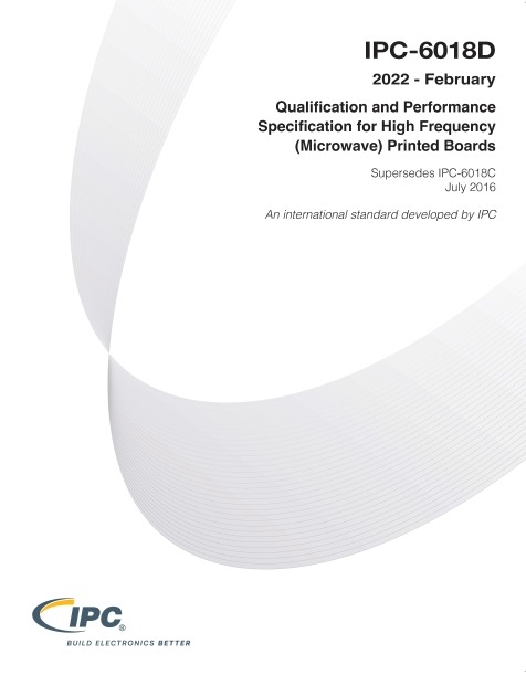
The IPC-6018 latest version question should be checked through IPC or authorized standards distributors before releasing a fabrication drawing. As of the latest source check, IPC-6018D is listed as the current Revision D document for “Qualification and Performance Specification for High Frequency Microwave Printed Boards.” The official IPC shop page lists IPC-6018D, Revision D, Standard Only, in English.
The related space and military avionics addendum is IPC-6018DS, dated August 2022. IPC states that the addendum supplements or replaces specifically identified requirements of IPC-6018D for high frequency microwave printed boards that must survive vibration, ground testing, and thermal cyclic environments of space and military avionics.
The difference between the two documents is important:
- IPC-6018D is the base specification.
- IPC-6018DS is an addendum for space and military avionics applications. It should be used with the base document when procurement documentation requires it.
For new drawings, avoid vague notes such as “meet IPC standard.” A better note states the exact document, class, addendum if required, material, impedance tolerance, acceptance test, and record requirements.
Where Can You Find the Official Document of IPC 6018 PDF?
The official document should be purchased or accessed through IPC or authorized standards channels. Free copies found on random websites may be outdated, incomplete, or not licensed for company use. For compliance driven projects, always use a licensed document and confirm the revision before releasing a purchase order.
- Official IPC standards store: https://shop.electronics.org/; This is the Global Electronics Association store for IPC standards and related documents.
- Official IPC 6018 product page: https://shop.electronics.org/ipc-6018; This page lists IPC 6018 for high frequency microwave printed boards.
- Official IPC-6018D standard page: https://shop.electronics.org/ipc-6018/ipc-6018-standard-only/Revision-d/english; This page lists IPC-6018D, Revision D, Standard Only, English version.
- Official IPC-6018DS addendum page: https://shop.electronics.org/ipc-6018/ipc-6018-addendum/Revision-d/english; This page lists the space and military avionics applications addendum to IPC-6018D.
- Official IPC-6018DS table of contents PDF: https://www.electronics.org/TOC/IPC-6018DS_TOC.pdf; This PDF confirms the addendum title, scope, and relationship to IPC-6018D.
FAQs About IPC-6018 Standard
Q1: When should a project specify IPC 6018 instead of a normal PCB fabrication standard?
A1: IPC 6018 should be specified when the board is designed for RF, microwave, radar, antenna, satellite communication, or other high frequency functions. It is especially useful when impedance stability, insertion loss, via performance, and laminate control affect final product behavior.
Q2: Can IPC 6018 be used for a rigid PCB made with FR4?
A2: It can be used when the FR4 board is part of a high frequency microwave design and the additional requirements are meaningful. For ordinary rigid FR4 boards, IPC 6012 is usually more suitable. For RF antenna boards using FR4, the design team should confirm whether IPC 6018 adds real process control value.
Q3: What should be written on a fabrication drawing when IPC 6018 is required?
A3: A clear drawing note should include the document revision, performance class, laminate name, stackup, copper thickness, surface finish, controlled impedance values, tolerance, test coupon requirement, inspection records, and whether IPC-6018DS applies.
Q4. Does IPC 6018 automatically define the impedance value for an RF PCB?
A4. No. The standard supports performance and acceptance control, but the exact impedance values must be defined by the design documentation. The drawing should state the target impedance, tolerance, reference layer, trace geometry, and coupon method where needed.
Q5: Why do RF PCB manufacturers ask for material brand and laminate thickness before quoting?
A5: RF performance depends heavily on dielectric constant, dielectric thickness, copper profile, and loss tangent. A small material change can affect impedance and insertion loss. That is why material details should be confirmed before quotation and production.
Q6: Is ipc 6018 class 2 enough for commercial RF products?
A6: In many commercial RF projects, ipc 6018 class 2 is suitable. It is commonly used for communication modules, wireless devices, test equipment, and industrial RF products where reliable long term service is needed.
Q7: When is ipc 6018 class 3 more suitable than Class 2?
A7: IPC 6018 class 3 is more suitable for high reliability applications where failure may cause serious cost, downtime, safety risk, or mission impact. Examples include aerospace RF modules, defense radar, satellite systems, medical RF equipment, and high value instrumentation.
Q8: What does IPC-6018DS add to a high frequency PCB project?
A8: IPC-6018DS adds space and military avionics related requirements to IPC-6018D. It is used when procurement documents require stronger controls for severe environments, including vibration, ground testing, thermal cycling, and mission critical service.
Q9: Why is annular ring tolerance important in IPC 6018 Class 3 RF boards?
A9: Annular ring tolerance affects via reliability and layer to layer connection quality. In dense RF multilayer boards, poor registration can increase the risk of breakout, weak interconnection, impedance drift, and inconsistent high frequency behavior.
Q10: How can buyers reduce disputes when ordering IPC 6018 RF PCBs?
A10: Buyers should send complete Gerber files, drill files, stackup, material requirements, impedance table, IPC class, surface finish, test coupon requirements, and inspection record expectations. Clear documentation helps the manufacturer quote accurately and build consistently.
You may also like


Tags: ipc 6012 vs 6018, ipc 6018, ipc 6018 pdf, IPC-6018, ipc-6018 class 3 annular ring tolerance multilayer registration