PCB manufacturing PCB manufacturing
Home > Blog

thermal vias

Thermal Via Solder Wicking: Protect the QFN Pad Joint
Monday, November 9th, 2026

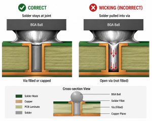
Thermal via solder wicking happens when molten solder enters a via opening connected to a package’s exposed land. On a power QFN, that can reduce solder remaining under the package or leave solder on the opposite side. Prevent it by deciding together which vias remain open, where paste is printed and what the assembly inspection must confirm.

Do not remove thermal vias just to make the solder process easier. Compare the via treatment and stencil pattern against the package guidance, electrical connection, thermal target and fabrication capability, then verify the assembled joint on representative hardware.
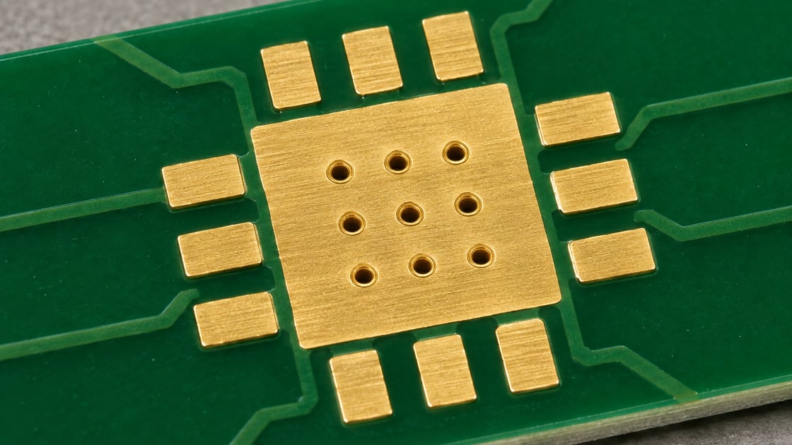
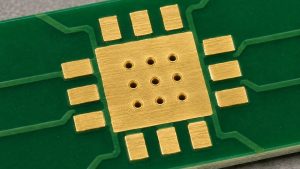
Unpopulated PCB land with several plated via openings
Via positions under a stencil aperture change how exposed openings interact with the paste. AI-generated illustration; not a production or test record.

thermal via solder wicking

An open, wettable via inside the pasted land creates a path for solder during reflow. The amount that enters depends on the opening, plating and wetting, available solder and process conditions. It is not enough to count vias or compute their empty volume. TI’s PowerPAD application report discusses controlling hole size and stencil placement for the packages it covers.

Check the actual joint for loss of solder and the reverse side for protrusion or deposits. Do not label every exposed-pad void as wicking; outgassing and paste or reflow behavior can also contribute.

thermal pad via design

Design the thermal and assembly paths as one set of requirements. The exposed pad may have an electrical connection as well as a thermal role; check its required net in the device datasheet. Draw the via array, finished hole openings, paste windows and mask openings on the same coordinate basis so both suppliers can review them.

Parameter Specify or verify
Finished hole Diameter and location
Via treatment Open, tented or capped
Paste windows Size and alignment
Thermal path Net, planes and copper
Evidence X-ray and thermal check

thermal vias size and spacing

Use the exact package recommendation and fabricator capability, not a universal hole diameter or pitch. Smaller openings may limit the solder available to flow into a barrel, but hole size, plating and pitch also affect the heat path and manufacturing yield. In a solder-risk review, ask where each opening lands relative to the stencil windows and what registration margin remains.

The thermal via design overview covers the separate heat-flow and resistance question. This article focuses on deciding which openings can safely remain beneath the soldered land.

should thermal vias be tented

Tenting is an option only if the selected side and mask process are suitable for the package and assembly route. A mask film spanning an opening is not a metal cap. Top-side tenting can affect the wettable pad area; reverse-side tenting leaves a top-side opening unless the stack or process specifies otherwise.

Ask whether the supplier can maintain the requested tent through fabrication and reflow at the finished hole size. Compare this with paste windows that avoid open vias, rather than treating tenting as a universal remedy.

thermal via filling

Specify what “filled” means before comparing quotes. A resin-filled via with a metal cap presents a different top surface from an open plated hole; a tented or merely plugged hole is not automatically planar or capped. A nonconductive fill does not remove the existing plated copper path, but it should not be modeled as a solid copper cylinder.

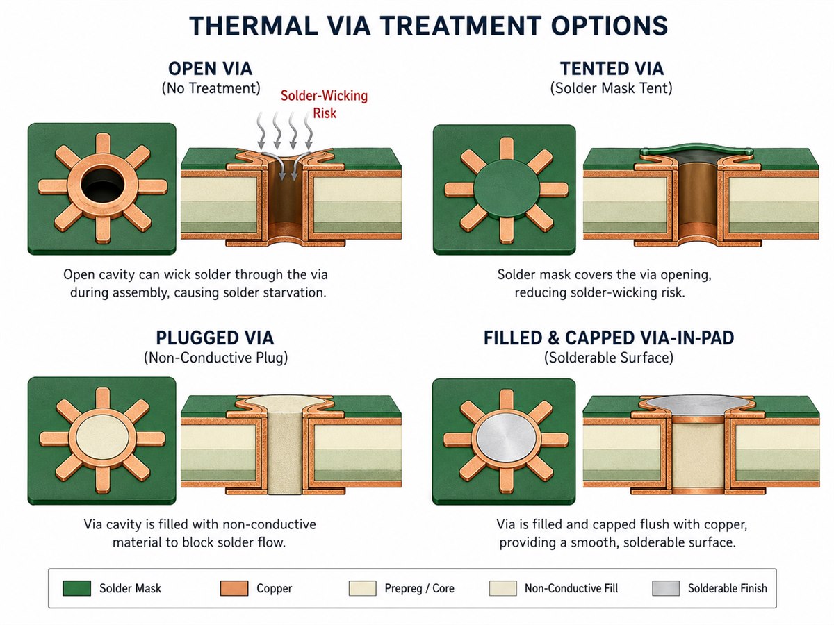
Option Top surface Check before release
Open plated via Opening exposed Paste clearance
Mask tent Mask film, if intact Side and coverage
Filled and capped Plated surface Flatness and cap integrity
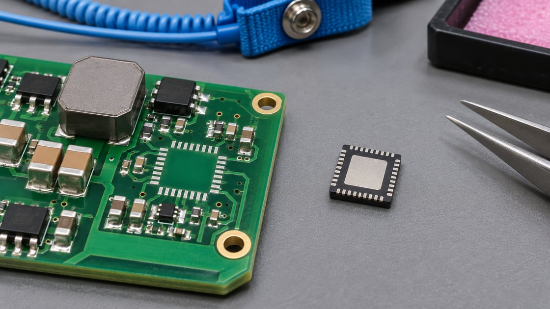
QFN-style component underside and a power PCB sample
Use the exact package drawing when setting the land and stencil geometry. AI-generated illustration; not a production or test record.

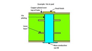
via in pad plated over

Filled and plated-over via-in-pad can be useful when an uninterrupted solderable land is needed. Confirm the fill, cap plating, finished planarity and inspection evidence rather than approving a quote based only on “VIPPO.” See the via-in-pad plated-over process guide for manufacturing details.

Compare the extra process requirements with an open-hole approach that positions stencil windows away from the vias. Both options need assembly verification. Capping addresses the open-hole path but does not remove every possible cause of voiding.

qfn ground pad stencil design

Segmenting the paste area can help the assembler control deposit distribution and avoid some open holes. Use the package and assembly process recommendations; the stencil thickness and pattern must also suit the peripheral joints. TI’s QFN and SON attachment guidance discusses exposed-pad stencil options and X-ray evaluation.

For a drawing check only, four 1.2 mm square windows on a 3.0 mm square exposed land occupy 5.76 mm² of the 9.00 mm² land, or 64% area. With a 0.10 mm stencil, their theoretical aperture volume is 0.576 mm³. Neither value is a recommended target or a prediction of deposited solder; transfer efficiency and reflow change the result. Inspect the actual printed pattern before treating the layout as qualified.

qfn solder void

Look at the void pattern, remaining joint coverage and any solder on the reverse side together. A two-dimensional X-ray can help locate voids, but it does not by itself prove how a void formed or how much solder entered a specific via. Compare the image with the via locations, stencil layout and process records.

Before approving the design, agree the package-specific acceptance criteria with the assembly team. If the cause is still unclear, choose targeted cross-sections or another agreed inspection. Check the assembled board’s temperature under representative power and ambient conditions; a neat-looking X-ray is not a thermal qualification.

FAQ

Does every open thermal via wick solder?

No. The via and land must interact with molten solder under the actual process conditions. The risk depends on wetting, hole geometry, paste placement and reflow. Inspect both sides of representative assemblies and check the joint before treating a given arrangement as safe.

Is tenting on the bottom the same as a filled and capped via?

No. A mask tent can cover one opening but does not create a plated, planar top land. A filled and capped via uses a different fabrication sequence. Ask for the treatment and inspection details in the fabrication drawing instead of relying on an abbreviated label.

Can I simply reduce the amount of paste to stop wicking?

Reducing paste everywhere can leave an insufficient joint even if less solder travels down the hole. First review where paste overlaps the openings and what the package guidance calls for. Use measured paste deposits and assembled-joint evidence rather than adjusting total paste area alone.

Why are there solder deposits on the opposite side of the board?

An open via connected to the land can be a route for solder during reflow, but other solder processes can also leave deposits. Correlate their locations with the via map and record the assembly sequence. Inspect the top joint rather than assuming the reverse deposit is harmless.

Can a large void prove the exposed pad is not soldered?

A single X-ray view can show a projected void, not the full thickness or shape of a joint. Compare the image with the agreed criteria and inspect the location relative to the pad and vias. Use a suitable follow-up method if the diagnosis affects acceptance.

Will resin-filled vias provide the same thermal result as copper-filled vias?

Do not assume that they will. The barrel, fill, cap and connected planes contribute differently to heat flow. Use the actual cross-section and material properties in a thermal model, then confirm the assembled board when the temperature margin is small.

What must I tell the fabricator before selecting a via treatment?

Provide the package drawing, exposed land and via locations, finished hole sizes, affected sides and required surface condition. Also identify which features must be inspected and whether the assembler expects a flat solderable land. Get the treatment description accepted before releasing the files.

Should I compare a modified stencil using the same assembly process?

Yes, when practical. Keep the package, board, paste and reflow conditions comparable so changes are attributable to the stencil trial. Record print results, joint images and thermal checks together. If several inputs change at once, do not attribute the result to one adjustment alone.

Discuss Your Project

Send Best Technology the device drawing, pad and via layout, finished hole sizes and preferred treatment. Include the stencil and inspection requirements if they are already agreed. Contact sales@bestpcbs.com.


You may also like

Thermal Vias in PCB Design: How They Work, Size, Spacing, and Thermal Resistance
Friday, July 31st, 2026

A PCB can have correct electrical routing and still run too hot. The problem is often not the component alone, but the lack of a low-resistance path from its exposed pad into the board.

Designers use thermal vias to provide that path. They move heat through the PCB to internal copper, bottom-side copper, or an external heat sink. They are commonly used under QFN packages, MOSFETs, power ICs, LEDs, processors, and motor-control devices.

Their performance depends on the complete heat path, not just the number of holes. Finished hole size, plating thickness, PCB thickness, via pitch, copper area, filling method, and assembly process all matter.

Thermal vias in a multilayer PCB transferring heat from a component into internal and bottom copper layers

What Are Thermal Vias in PCB Design?

Thermal vias are plated holes used mainly to transfer heat between PCB layers. They normally connect a hot surface pad to internal planes or a bottom-side copper area.

A thermal via may look identical to an electrical via, but its design intent is different. Signal vias are placed where routing requires them. Thermal vias are usually grouped beneath or close to a heat-generating component.

Typical applications include:

  • QFN and DFN exposed pads
  • Power MOSFETs
  • DC-DC converters
  • High-power LEDs
  • Motor drivers
  • RF power devices
  • Processors and communication modules

The copper barrel provides the main vertical heat path. FR4 conducts heat poorly compared with copper, so the plated hole wall makes the structure effective.

Thermal vias do not remove heat on their own. They move it to a larger copper area, internal plane, chassis, thermal interface pad, or heat sink. If the receiving copper is too small, adding more vias provides limited benefit.

How Do Thermal Vias Work?

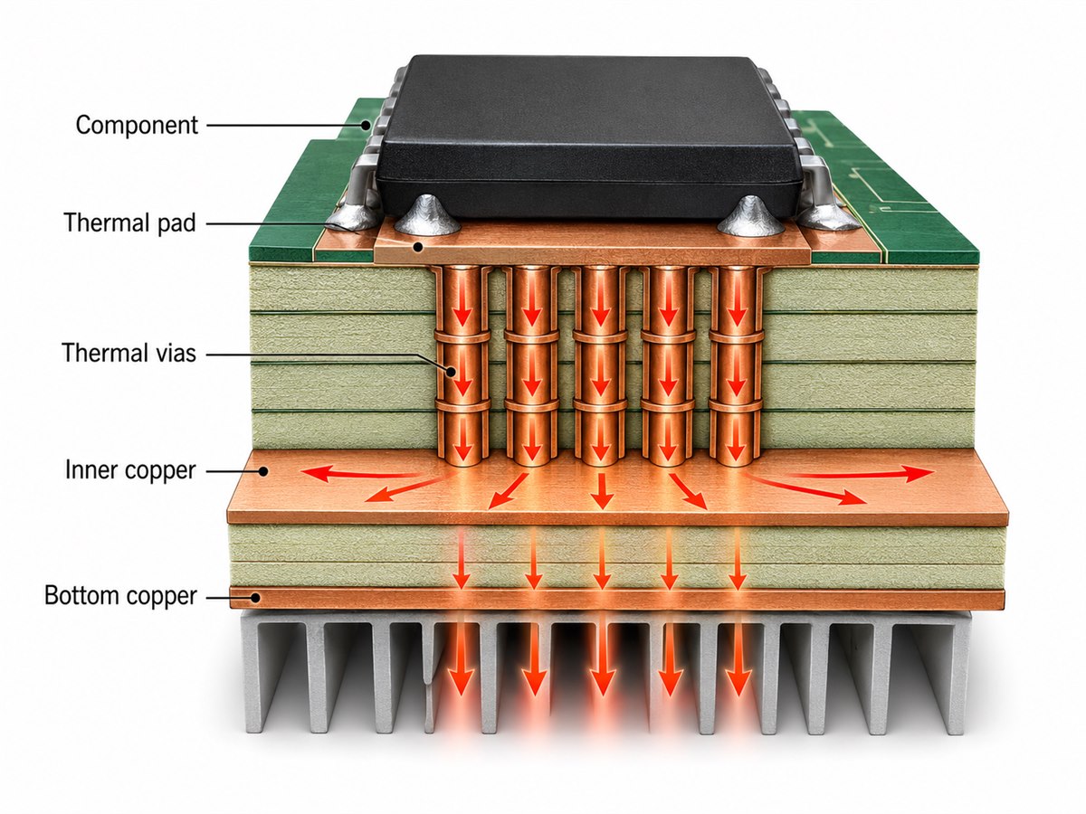
Cross-section showing heat flowing from a PCB component through a thermal pad, thermal vias, inner copper and bottom copper to a heat sink

A typical heat path is:

Silicon junction → package pad → solder joint → top copper → via barrels → internal or bottom copper → ambient air or heat sink

The via array performs two jobs:

  • Vertical conduction: Moves heat through the board
  • Lateral spreading: Feeds heat into larger copper areas

Both are necessary. A dense array connected to a small copper island can perform worse than a moderate array connected to a broad plane.

Board thickness also matters. A longer via has higher thermal resistance. A 3.2 mm PCB therefore needs more careful review than a 1.0 mm or 1.6 mm board using the same hole size.

The final cooling path must also be practical. In a sealed enclosure, bottom copper alone may not dissipate enough heat. Connecting it to a metal housing through a thermal interface material can provide a much larger improvement.

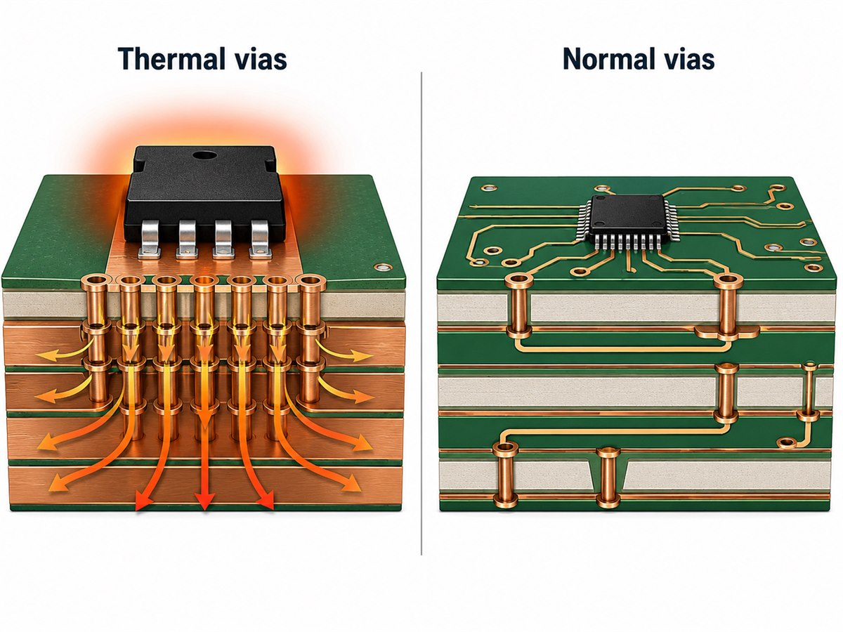
Thermal Vias vs Normal Vias

The main difference is purpose, placement, and connection strategy.

Comparison between a dense thermal via array under a hot component and normal signal vias used for PCB routing
Design factor Thermal via Normal signal via
Primary function Heat transfer Electrical interconnection
Typical placement Under or near hot components Along signal routes
Arrangement Usually an array Usually individual
Main concern Thermal resistance Connectivity and signal integrity
Plane connection Broad copper connection Trace or assigned plane
Filling need Sometimes required Usually unnecessary

A thermal via may also carry current when connected to ground, power, or a MOSFET pad. In that case, thermal and electrical requirements must be checked together.

Thermal vias are not thermal reliefs. A thermal relief reduces heat flow into a plane to improve solderability. A thermal via is intended to increase heat transfer through the PCB.

Where Should Thermal Vias Be Placed?

The best location is usually directly under the exposed thermal pad. This shortens the path from the heat source to the via barrel.

When via-in-pad is not practical, place the vias as close to the hot pad as fabrication and routing rules allow.

Use these placement rules:

  • Cover the active thermal-pad area rather than only its edges
  • Connect the array to continuous copper
  • Avoid narrow copper necks between the pad and vias
  • Use solid plane connections unless soldering requires otherwise
  • Confirm the exposed pad’s electrical net
  • Provide enough bottom or internal copper to spread heat
  • Keep temperature-sensitive parts away from the main heat path

A rectangular or staggered array usually works better than a single line of vias under a rectangular pad.

What Thermal Via Size Should You Use?

Thermal vias size depends on board thickness, pad area, plating, filling method, and manufacturing capability; there is no universal finished-hole diameter.

For many standard multilayer PCBs, a finished hole of about 0.20 mm to 0.35 mm is a practical starting point. The final value should come from the component land pattern and the PCB fabricator’s process limits.

Check these dimensions together:

  • Finished hole diameter
  • Drill diameter
  • Via pad diameter
  • Annular ring
  • Barrel copper thickness
  • PCB thickness
  • Aspect ratio

Larger holes provide more barrel area, but they consume more pad space and can draw more solder if left open. Smaller holes allow a denser array, but they may increase fabrication cost or require filling.

The fabrication drawing should specify the finished hole size. Drill size alone does not define the final plated diameter.

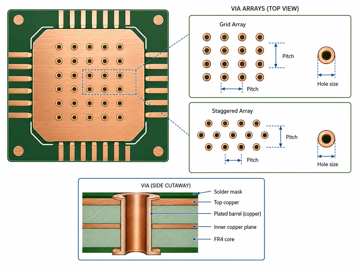
How Should Thermal Vias Be Spaced?

Top-view grid and staggered thermal via arrays with callouts for via hole size, pitch and plated barrel construction

Spacing should balance thermal coverage, copper continuity, drilling capability, and solder behavior.

For many exposed-pad designs, a center-to-center pitch of roughly 0.5 mm to 1.0 mm is a useful starting range. The final pitch must be checked against:

  • Finished hole diameter
  • Via pad diameter
  • Minimum hole-to-hole spacing
  • Annular-ring requirements
  • Remaining copper between vias
  • Stencil and solder-paste design

If vias are too far apart, heat travels farther through the top copper before reaching a hole. If they are too close, the pad becomes heavily perforated and manufacturing becomes more difficult.

Common patterns include rectangular grids, staggered grids, and dense center arrays with wider spacing toward the edges.

How Many Thermal Vias Do You Need?

The quantity should be based on heat load, available area, and the complete cooling path.

A practical process is:

  1. Estimate maximum continuous and transient power loss.
  2. Set the maximum acceptable junction or case temperature.
  3. Review the package manufacturer’s thermal land pattern.
  4. Estimate one via’s thermal resistance.
  5. Calculate the ideal parallel resistance of the array.
  6. Include copper spreading and external cooling.
  7. Validate the design through simulation or prototype testing.

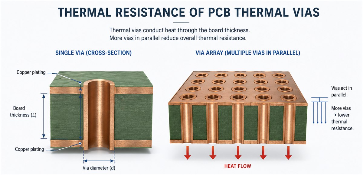
Nine identical vias have about one-ninth the ideal vertical resistance of one via. The total board temperature does not improve at the same rate because the package, copper plane, interface material, and convection eventually become the main limits.

For a small regulator, a 3 × 3 array may be enough. A high-power MOSFET may need more vias, heavier copper, a chassis connection, or a different substrate.

How Is the Thermal Resistance of a Via Calculated?

Thermal resistance calculation for one plated PCB via and an array of vias acting in parallel

A simplified conduction model is:

Rθ via = L / (kA)

Where:

  • L is the via length
  • k is the thermal conductivity of the barrel material
  • A is the effective copper cross-sectional area

For a thin plated barrel:

A ≈ πdt

Where d is the finished hole diameter and t is the barrel copper thickness.

Consider this example:

  • PCB thickness: 1.6 mm
  • Finished hole: 0.30 mm
  • Barrel copper: 25 µm
  • Copper conductivity: approximately 385 W/m·K

The simplified thermal resistance is about 176°C/W per via. Nine identical vias provide an ideal array resistance of approximately:

176 / 9 ≈ 19.6°C/W

This is not the complete junction-to-ambient thermal resistance. It excludes:

  • Package resistance
  • Solder-joint resistance
  • Copper spreading resistance
  • Fill-material effects
  • Bottom copper or heat-sink resistance
  • Convection and radiation

Use the calculation to compare thermal via designs, not to predict final component temperature by itself.

How Should You Use a Thermal Via Calculator?

A thermal via calculator is useful for screening design options before simulation or testing.

Typical inputs include:

  • Board thickness
  • Finished hole diameter
  • Barrel copper thickness
  • Number of vias
  • Fill material
  • Copper-plane size
  • Component power
  • Allowed temperature rise

Use finished hole diameter rather than drill-tool diameter. Also enter the specified hole-wall copper thickness instead of relying on a default value.

Compare one change at a time, such as:

  • 0.20 mm versus 0.30 mm holes
  • Nine versus sixteen vias
  • 1.0 mm versus 1.6 mm board thickness
  • Open versus filled structures

For automotive, medical, sealed, or high-power products, confirm the result with thermal simulation and prototype measurements.

How Should Thermal Vias Be Designed in a Thermal Pad?

Thermal vias in pad areas provide a short heat path, but they can create assembly problems. Review the related via-in-pad design and fabrication requirements before release.

Open holes may draw solder away from the component pad. Excessive solder wicking can cause:

  • Low solder volume
  • Voiding
  • Package tilt
  • Uneven stand-off
  • Inconsistent thermal contact

Small open vias may be acceptable in some prototypes, but only when the hole size, stencil aperture, paste volume, and opposite-side termination are controlled.

For fine-pitch or higher-reliability products, filled and capped vias provide a flatter surface. A common process uses non-conductive epoxy filling, planarization, and copper capping.

Review these items together:

  • Via diameter and quantity
  • Fill and cap requirements
  • Surface planarity
  • Solder-mask opening
  • Segmented stencil apertures
  • Allowable voiding
  • X-ray inspection criteria

The component manufacturer’s land pattern should be the starting point, then adjusted for the actual PCB and assembly process.

Should Thermal Vias Be Tented, Plugged, Filled, or Left Open?

The treatment depends mainly on whether the via is inside a solderable pad and whether a flat surface is required.

Comparison of open, tented, plugged, and filled and capped thermal via treatment options
Via treatment Best fit Main benefit Main limitation
Open Outside solderable pads Lowest cost Can collect solder or contamination
Tented Small vias under solder mask Protects the opening Coverage may be incomplete
Plugged Holes that must be blocked Reduces solder flow May not create a flat surface
Non-conductive filled and capped Via-in-pad assembly Flat, stable solder surface Higher cost
Conductive epoxy filled Selected thermal or electrical use Adds conductive fill Lower conductivity than copper
Copper filled Advanced high-performance designs Strong vertical conduction Specialized and expensive

Tenting is not a guaranteed seal. Hole size, mask thickness, and coating side all affect coverage.

Single-sided tenting can also trap moisture or process chemicals. The fabricator may recommend double-sided tenting, plugging, or filling.

For most standard via-in-pad applications, non-conductive fill with copper capping offers a practical balance between assembly reliability and cost.

How Do Thermal Stitching Vias Work with Copper Planes and Heat Sinks?

Thermal stitching vias connect copper areas on several layers so they work as one heat-spreading structure.

A common multilayer arrangement links:

  • Top thermal pad
  • Internal ground or power plane
  • Bottom copper area
  • Optional chassis or heat sink

Internal planes spread heat but do not remove much of it from the product. The final temperature still depends on airflow, enclosure design, exposed copper, and any external heat sink.

For chassis-cooled products, review:

  • Electrical isolation
  • Interface-material thickness
  • Surface flatness
  • Compression force
  • Thermal conductivity
  • Mechanical tolerance

If standard FR4 with thermal vias cannot meet the target, alternatives may include IMS, ceramic PCB, copper coins, embedded copper, or direct heat sinking.

What Manufacturing Limits Affect Thermal Via Design?

An effective thermal design must also be repeatable in production.

Check these fabrication limits before release:

  • Minimum mechanical drill
  • Finished-hole tolerance
  • Maximum aspect ratio
  • Minimum annular ring
  • Minimum via-to-via spacing
  • Hole-wall copper thickness
  • Fill and planarization capability
  • Copper-cap thickness
  • Solder-mask tenting limit
  • Registration tolerance
  • Inspection and microsection requirements

Filled and capped vias require extra process stages, which affect cost, lead time, and yield.

For quotation, provide:

  • Gerber and drill files
  • PCB thickness and stack-up
  • Finished hole and pad dimensions
  • Copper weight
  • Hole-wall copper requirement
  • Fill, plug, or cap notes
  • Surface finish
  • Solder-mask opening
  • Production quantity
  • Reliability class and inspection requirements

At EBest Circuit, we can review thermal via arrays, via-in-pad structures, stack-up, fill notes, and assembly conditions before quotation. Clear fabrication notes are important because similar-looking layouts can require very different processes.

What Are Common Thermal Via Design Mistakes?

  • Adding many vias without enough receiving copper
  • Placing the array too far from the heat source
  • Treating the via as a solid copper cylinder
  • Ignoring board thickness and hole-wall copper
  • Using large open holes beneath solderable pads
  • Connecting the exposed pad to the wrong net
  • Copying a reference pattern without checking actual power loss
  • Assuming conductive epoxy performs like copper
  • Ignoring stencil segmentation
  • Using one-sided tenting without process review
  • Relying on a calculator without prototype testing

FAQs About Thermal Vias

What is the purpose of thermal vias in PCB design?

Their purpose is to conduct heat through the PCB from a hot component pad to internal copper, bottom copper, or an external cooling structure. They reduce the vertical portion of the board’s thermal resistance.

How do thermal vias work?

Copper plated onto the hole wall conducts heat through the board. The connected copper planes then spread the heat over a larger area or transfer it to a heat sink.

What size should thermal vias be?

A finished hole between approximately 0.20 mm and 0.35 mm is a common starting range for conventional thermal-pad arrays. The final size depends on board thickness, aspect ratio, pad area, filling process, and fabrication capability.

How many thermal vias should I use?

The quantity should be based on component power, allowable temperature rise, available pad area, board thickness, via dimensions, and the external cooling path. The component manufacturer’s recommended land pattern is a useful starting point.

Should thermal vias be placed directly under a component?

They should normally be placed directly under an exposed thermal pad when the package, electrical net, fabrication process, and assembly method allow it. This position minimizes lateral heat-travel distance.

Should thermal vias be tented?

Tenting may be suitable for small holes outside solderable pads. Via-in-pad designs usually need more controlled treatments such as plugging or filling and capping.

Should thermal vias be filled with solder?

Intentionally filling ordinary vias with solder is not always reliable because voids can remain and the solder distribution may be inconsistent. A specified resin-fill or copper-fill process provides better process control.

Do filled vias transfer more heat than open vias?

They can, but the improvement depends on the filling material. Conductive epoxy transfers more heat than air but generally much less than copper. Copper-filled structures offer stronger conduction but cost more.

Can thermal vias connect to a ground plane?

Yes, when the component’s thermal pad is electrically connected to ground. Always confirm the package pin definition before connecting the via array to any plane.

Are thermal vias the same as thermal reliefs?

No. Thermal vias increase heat transfer through the PCB. Thermal relief spokes restrict heat flow between a solder pad and a large copper area to make soldering easier.

What is the difference between thermal vias and normal vias?

Their physical construction may be similar, but thermal vias are arranged and connected specifically for heat transfer. Normal vias are mainly used for electrical routing.

Can thermal vias replace a heat sink?

They can reduce PCB thermal resistance, but they cannot always replace a heat sink. High-power devices may still require a chassis connection, metal substrate, heat spreader, airflow, or external heat sink.

Conclusion

Thermal via performance depends on the complete heat path: component pad, via barrels, copper planes, interface materials, and external cooling. More vias are useful only when they connect to enough copper and remain compatible with fabrication and soldering requirements.

For an accurate quotation, provide the Gerber files, stack-up, finished hole dimensions, copper specifications, via-fill notes, assembly requirements, and expected production quantity.

For thermal via DFM review, via-in-pad fabrication, multilayer PCB production, or PCBA assembly, contact EBest Circuit at sales@bestpcbs.com.

You may also like