PCB manufacturing PCB manufacturing
Home > Blog

thermal cycling

DBC Copper Edge Relief: How to Check Thermal-Cycle Risk
Friday, November 6th, 2026

Copper edge relief is a local reduction of copper near a pad perimeter on a direct-bonded copper (DBC) ceramic substrate. It can reduce stress near the copper edge during temperature cycling, but it is not a universal pattern or a guaranteed life extension. Compare a relieved layout with an unrelieved control, and check that the remaining copper still meets the electrical, thermal and assembly requirements.
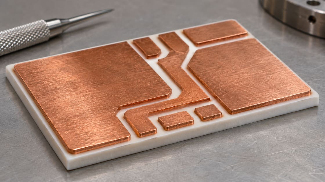
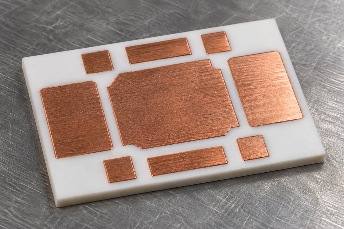
Patterned copper on a white ceramic substrate
Patterned copper on a white ceramic substrate. AI-generated illustration, not a measurement or production record.

Why cracks can start beside a copper pad

Copper and ceramic expand by different amounts when the temperature changes. Because they are bonded, each constrains the other, and stress can concentrate near a copper island’s perimeter. Rogers’ reliability discussion describes this mechanism in metallized ceramic substrates. It does not imply that every crack in that region has the same cause.

What edge relief changes

A relief feature changes the copper section near an edge rather than changing the whole ceramic. One supplier implementation uses shallow copper dimples near pad edges. A supplier drawing should distinguish a recess in copper from a through-hole or a gap in the electrical pattern. For the underlying construction, see this overview of DBC ceramic substrates.

Which dimensions to include in the comparison

Record the full stack and the remaining copper where the relief is deepest. There is no universal dimple size or pitch suitable for every design.

Field Unit or basis What to compare
Ceramic and thickness Grade and mm Same grade and thickness in the control and relief variant
Front and back copper Finished thickness in mm Both faces, not just the component side
Relief geometry Width, spacing and distance from edge in mm Features aligned to a documented datum
Residual copper Minimum remaining thickness in mm Section where current or spreading heat could be constrained
Temperature cycle Low and high setpoints in °C; dwell and ramp Same defined test profile for both variants
Failure criterion Agreed inspection and functional limits Same initial baseline and end criterion

Relief vs copper balance vs changing the substrate

Start with the change that addresses the observed mechanism and is feasible for the application.

Option What it changes What else to verify
Local copper edge relief Copper section near selected perimeter zones Remaining current path, inspectability and usable attach area
Copper distribution adjustment Front-to-back pattern balance Flatness, insulation spacing and whether the change alters other copper features
Different ceramic or bonding system Material and interface behavior Thermal performance, electrical isolation, supply and qualification
Unrelieved control Retains the original edge and stack Baseline against which proposed improvements are measured

How to keep relief away from the current path

Check the narrowest conducting section, not just the nominal copper thickness in the order. Imagine a power terminal feeding a copper island along one edge. Relief along the opposite unused perimeter may have a different impact from relief under the terminal feed. If the pattern intrudes into a high-current neck, check the actual remaining section before approving it. In a purely illustrative stack with 0.30 mm finished copper and a 0.08 mm recess, the nominal copper remaining at the recess bottom is 0.22 mm. Those figures are not a recommendation or a current rating; check the toleranced section and the actual current path.

How to protect the die-attach area

Keep the proposed relief separate from the die footprint and required attach land unless the assembly has been designed and qualified for that geometry. Check where heat enters the substrate and where the copper spreads it. A mechanically helpful detail can still be unacceptable if it reduces the attachment area or changes the thermal path.
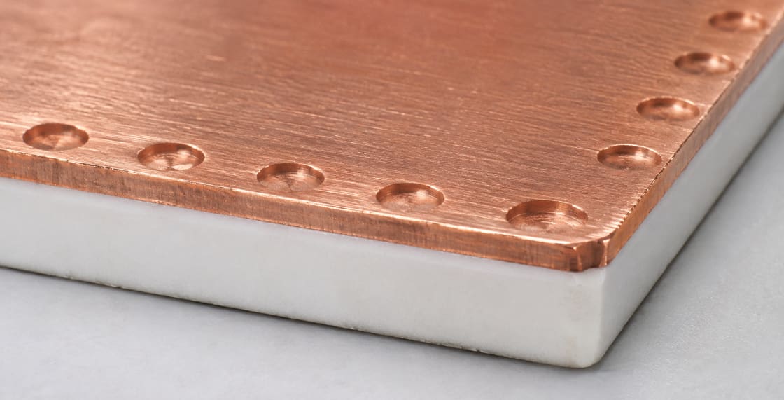
Shallow recesses near the edge of a copper pattern
Shallow recesses near the edge of a copper pattern. AI-generated illustration, not a measurement or production record.

Why the back copper belongs in the drawing

Record both faces because the stress depends on the whole cross-section and pattern. A nearly solid back face and a heavily segmented front face are not equivalent to two matching patterns. Review the copper-free perimeter, alignment and flatness along with the relief itself.

How to make a meaningful test coupon

Build a control and a relief variant that differ only in the intended feature where practical. Use the same ceramic, copper construction, layout at the area of interest and relevant assembly conditions. If a supplier also changes the ceramic, the test compares two systems rather than isolating the effect of relief.

Which temperature-cycle details belong in the report

Record setpoints, dwell, ramp or transfer conditions, fixture configuration and inspection intervals. Two tests with the same cycle count can impose different stress histories. An accelerated result ranks specimens under those conditions; it does not directly predict service life.

How to tell whether an indication matters

Locate the indication relative to the die, contact pads, copper edge and insulation boundary. A scanning acoustic microscopy image can help locate internal indications on a suitable sample, but interpret it with the baseline and geometry. When the heat path is at issue, correlate the inspection result with a relevant thermal measurement.

What to review if the modified pad still cracks

Compare the failure sites across control and variant. If cracks shift rather than disappear, review ceramic edges, copper pattern balance and local geometry. If both variants fail at a similar location, check specimen preparation, attachment conditions and the proposed failure mechanism before adding more relief.

What to send for a substrate review

Provide both copper layouts, the substrate grade, nominal and minimum dimensions, attach locations, operating temperature profile and qualification criteria. For manufacturing review, send the package to Best Technology at sales@bestpcbs.com and identify the required evidence rather than requesting a generic dimple pattern.

FAQ

Does every DBC substrate need dimples?

No. The decision depends on the construction and the failure mechanism in the intended use. A supplier may use a different geometry or material strategy. Compare against a control under the same conditions rather than treating the feature as mandatory.

Are dimples the same as copper vias?

No. In this context a dimple refers to a localized recess in the copper intended to change the edge geometry. It is not a plated interconnect. Confirm the depth and residual thickness in a section drawing rather than inferring the structure from a top-view photo.

Can thermal cycling tell me how long the product will last?

Not on its own. The test compares specimens under a defined temperature history. Service conditions also involve the operating profile and the assembled module. A lifetime claim needs a justified relationship between those conditions and the observed mechanism, supported by suitable validation.

Can I transfer the same geometry from alumina DBC to another ceramic?

Do not assume it transfers unchanged. Ceramic properties, copper thickness, joining system and geometry all affect stress. Treat a substrate change as a new design input and confirm the geometry and qualification plan for that particular construction. Keep the original test result tied to its original stack.

Is a visible ceramic crack always caused by copper expansion?

No. The position can suggest a mechanism, but handling, machining, assembly and pre-existing defects also need consideration. Use baseline inspection, test history and failure analysis to separate a cycling-related change from an indication that was already present. Compare equivalent locations across samples.

Will thicker copper always be worse?

No universal rule covers every geometry and stack. Extra copper can support current and heat spreading while increasing stress in some constructions. Compare the full system under the agreed electrical, thermal and mechanical conditions rather than ranking it by one thickness.

Should I compare copper relief on both faces at the same time?

If you want to isolate the effect of relief on one face, keep the other face unchanged in the control. If both faces must change in production, a separate matched test can evaluate the combined configuration. Label the two comparisons separately in the report.

Can I approve the design using an acoustic image alone?

Use the agreed acceptance criteria. An image can locate an indication but may not quantify its electrical or thermal consequence. Keep the baseline images and correlate them with relevant measurements if the indication lies near a critical function. Record the inspection resolution and interpretation limits.
You may also like

Ceramic Substrate CTE: Why Copper Pad Edges Crack
Friday, November 6th, 2026

Copper and ceramic do not expand by the same amount when heated. Bond them together, and they cannot move independently. That mismatch can concentrate stress at the edges of copper pads. Here is how to estimate the mismatch and decide what needs testing before choosing a substrate for a power module.

What Does Ceramic Substrate CTE Mean?

CTE is the coefficient of thermal expansion. A value of 5 ppm/K means a free, uniform piece changes length by about five millionths of its original length for each kelvin of temperature change, within the range where that coefficient applies. A one-kelvin change has the same magnitude as a one-degree Celsius change.

Patterned copper on a white ceramic power substrate
AI-generated illustration of a metallized ceramic substrate, not a qualified part.

Detailed CTE Parameters for Bare Ceramic Materials

The following bare ceramic values come from the Rogers curamik substrate specifications. They are material examples over a stated range, not guaranteed properties for every grade or the effective CTE of the finished part.

Bare ceramic Linear CTE Stated temperature range
— — —
Alumina 6.8 ppm/K 20°C to 300°C
Aluminum nitride 4.7 ppm/K 20°C to 300°C
Silicon nitride 2.5 ppm/K 20°C to 300°C

Alumina vs Aluminum Nitride: Which Interface Matters?

Review point Alumina example Aluminum nitride example
— — —
Free expansion relative to copper Smaller mismatch in the worked example Larger mismatch in the worked example
Heat transfer through the ceramic Compare actual grade and thickness Often chosen for higher conductivity; verify the grade
Qualification decision Compare the full bonded stack Compare the full bonded stack

A ceramic closer to the expansion of copper is not necessarily closer to the expansion of the semiconductor die. Identify which interface is driving the failure before treating any one material property as the selection rule.

Why Copper Edges Are More Vulnerable

Away from a pad edge, the joined layers constrain each other. At the edge of the metal, that constraint changes abruptly. Rogers’ reliability discussion identifies pad edges and corners as stress concentration sites. A crack near the edge still needs failure analysis to rule out other causes.

Worked Example: A 20 mm Pad and a 100°C Swing

For an illustrative uniform temperature rise from 25°C to 125°C, assume copper CTE is 17 ppm/K and use the data sheet’s average alumina value of 6.8 ppm/K as an approximation. The difference in free length change is 20 mm × (17 − 6.8) × 0.000001/K × 100 K, or about 0.0204 mm. Using the listed aluminum nitride value gives about 0.0246 mm instead.

Why the Example Is Not a Stress or Lifetime Prediction

The calculated values compare two unbonded materials that would otherwise expand freely. They are not actual slip, crack opening, or deformation of the bonded part. Stress also depends on elastic and plastic behavior, geometry, temperature gradients, residual stress and restraint from the rest of the assembly.

What Copper Thickness and Pattern Change

Copper thickness and pad shape change the mechanical load carried by the ceramic. Corners, pad spacing and differences between the top and bottom patterns can influence the result. Ask the supplier to review the exact pattern rather than transferring rules from a different ceramic or joining process.

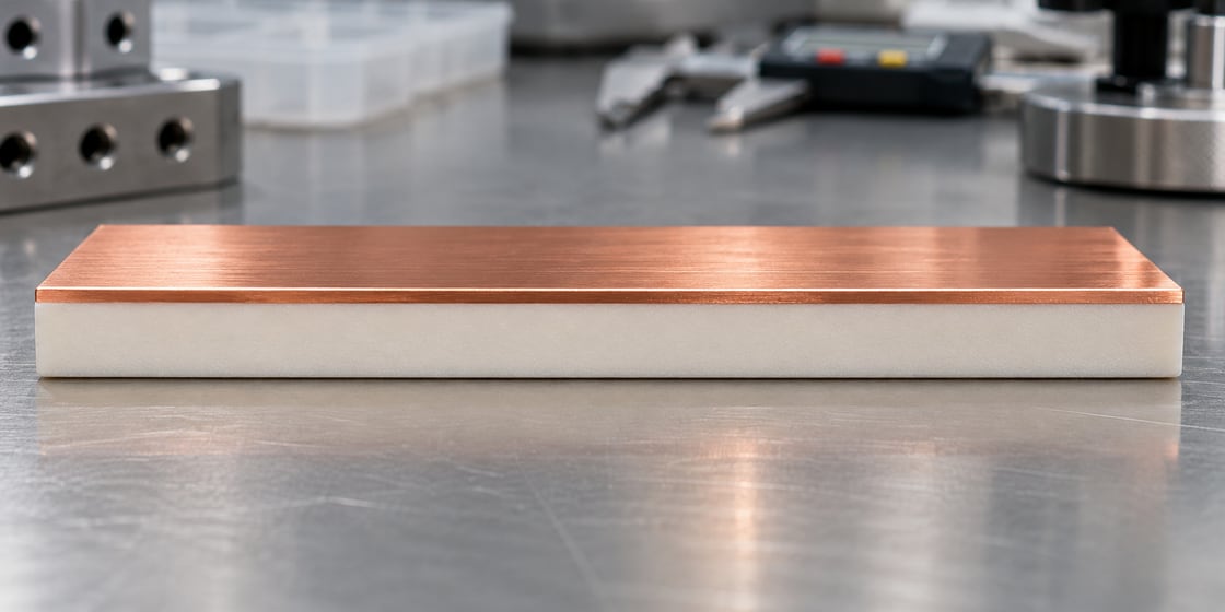
Side view of copper bonded to a white ceramic coupon
AI-generated illustration of a copper–ceramic interface, not a measured section.

When DBC and AMB Are Worth Comparing

Direct bonded copper (DBC) and active metal brazing (AMB) are different ways to join metal and ceramic. Compare the actual ceramic grade, bond structure, copper thickness and intended duty. A cycle count for one construction does not establish a cycle count for all substrates made with the same bonding method.

Thermal Cycling vs Power Cycling

A chamber test changes the ambient temperature around the specimen. A power cycling test changes the load in a powered device and can create different temperature gradients. Select a test based on where the real assembly heats and what failure mode you need to investigate.

How to Compare Two Substrates Fairly

Keep the pad geometry, attachment and inspection criteria consistent where possible. Record temperature limits, ramp rates, dwell times, sample sizes and inspection intervals. If you deliberately change copper thickness or another factor, record it as a variable rather than attributing every result to the ceramic.

What to Inspect After Cycling

Use the before-test condition as a baseline. Inspect representative copper corners and edges, and document the location and direction of any damage. Define whether the test is looking for ceramic cracking, bond separation, solder fatigue or an electrical change; these findings are not interchangeable.

What a Cross-Section Can Confirm

A section through the suspect edge can show whether a crack runs into the ceramic or whether separation follows an interface. Take a comparison section away from the damaged area if the inspection plan allows. Use those observations with the test history rather than assigning a failure mechanism from a surface photo alone.

What to Send for a Substrate Review

Send the ceramic grade, metal thicknesses, pad artwork, attachment method, temperature history and intended inspection criteria. For related construction information, see the DCB ceramic design guide. Contact Best Technology at sales@bestpcbs.com to discuss the design requirements.

FAQ

Does aluminum nitride always last longer than alumina?

No. Thermal conductivity and thermal cycling life answer different questions. A material that lowers the operating temperature may still behave differently at a copper edge or a solder joint. Compare substrates with representative geometry and attachment under a duty cycle relevant to your application before drawing a reliability conclusion.

Why do cracks start near the copper corner?

The copper ends at the edge, but the ceramic continues. The change in restraint concentrates stress near that boundary, particularly at corners. Location alone is not proof of a thermal expansion failure; compare inspection records, cross-sections and handling history before assigning a root cause.

Is the bare ceramic CTE the finished substrate CTE?

No. A metallized substrate combines materials with different expansion behavior, and the effective response depends on the construction. Use the bare ceramic value for material comparisons and early estimates. Ask for an appropriate measured or modeled property when the overall movement of the finished structure matters.

Can I calculate lifetime from the CTE difference?

No. The CTE difference gives a first estimate of how differently the free materials would move. It does not capture bonding, plastic deformation, fracture behavior or the true temperature field. Use modeling and testing to compare designs, and do not translate chamber cycles directly into field years without a validated model.

Should I make all copper pads smaller?

Not as a blanket rule. A smaller pad can change stress distribution, but it can also affect current flow, heat spreading, electrical clearances and assembly. Evaluate alternatives together with the supplier and test the resulting geometry rather than applying a universal size limit to different constructions.

What if only one side has a large copper area?

An uneven metal pattern can change how the substrate bends during heating and cooling. Include both sides in the design review rather than describing only the visible top pattern. Confirm the required flatness and check it under relevant conditions if warpage would affect attachment or assembly.

Can I use a chamber test instead of power cycling?

A chamber test is useful for a comparative evaluation, but it does not reproduce every gradient created by a powered die. Choose the test based on the suspected failure mechanism. A useful plan may use both methods if ambient cycling and local heating each matter in service.

Which drawings and data should I ask the supplier for?

Request the ceramic grade, thickness, copper pattern on both faces, joining method and documented test conditions for any reliability data. If the supplier shares cycle results, check whether the tested geometry and inspection criteria apply to your design before using those numbers as acceptance evidence.

You may also like