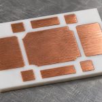
A power cycling test repeatedly heats a semiconductor die with its own electrical losses, then allows it to cool. In a power module built on a ceramic substrate, that temperature swing strains the interconnects and the layers carrying heat away from the die. The result describes the tested module and cooling boundary, not the lifetime of the bare ceramic material.
Suppose two prototype modules use the same ceramic grade but different die-attach processes. A steadily rising junction-to-case thermal resistance in one module is a reason to investigate its heat path, not proof that the ceramic cracked. First establish that both modules started from comparable thermal conditions and that the fixture did not change.
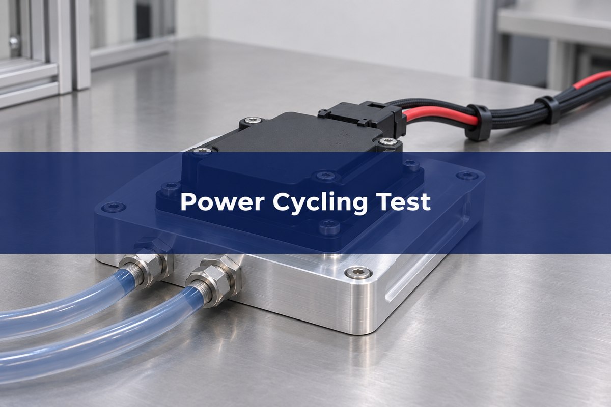
Power Cycling Test: What It Stresses
Active cycling starts by heating the die, so the die, its contacts and the deeper interfaces do not necessarily experience the same temperature swing at the same time. Copper, ceramic and attach layers expand differently. Repeating that stress can degrade bonds or joints along the path. A Fraunhofer IISB overview identifies active cycling as an accelerated module or device reliability test and separates it from thermal characterization.
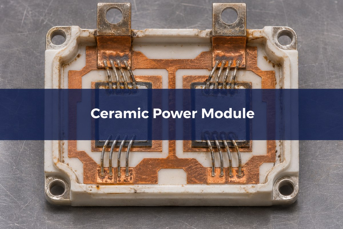
In a direct bonded copper (DBC) or active metal brazed (AMB) module, identify the die attach, top-side interconnect, copper-to-ceramic interfaces and underside of the substrate before testing. A change in electrical or thermal response tells you where to look first; deciding which layer changed requires evidence at that layer.
Power Cycling vs Thermal Cycling: Choose by Stress Source
Choose active power cycling when self-heating and the resulting internal gradient are central to the failure question. Use passive temperature cycling when changes in environmental temperature are the stress of interest. One result does not replace the other.
| Method | Stress source | Decision it supports |
| Short active cycling | Electrical self-heating, shorter heating periods | Assess response of the die and nearby connections; do not assume deeper joints are unstressed. |
| Longer active cycling | Electrical self-heating with more time for heat to spread | Assess response including deeper attach and heat-path joints, with cooling and heat-path geometry documented. |
| Passive temperature cycling | External chamber changes the temperature around the sample | Assess environmental expansion and contraction without assuming it reproduces the active junction gradient. |
For the two-module example, pick the heating duration to stress the intended path, then verify that the temperature response is relevant to the test question. For environmental loading on a bare substrate see the separate ceramic substrate thermal shock guide.
Power Cycling Test Standard: What AQG 324 Specifies
The ECPE AQG 324 Release 04.1/2025 is an automotive power-module qualification guideline, not a generic ceramic-board acceptance specification. Its active power-cycling procedures distinguish PCsec and PCmin. Specify the applicable revision and procedure when requesting a report; a test described only as “power cycled” does not establish equivalence.
Compare the start-of-test quantities and controlled settings, not just cycle counts. A documented virtual junction swing from one method has meaning only with the underlying measurement procedure, timing and cooling conditions. Ask the laboratory to identify which standard values apply and which project-specific limits were agreed before testing.
| Report field | Unit or record | Why it changes interpretation |
| Virtual junction temperature endpoints | °C; also report swing in K or °C difference | Equal swings at different endpoints need not impose the same aging. |
| Load current and on/off intervals | A and s; state control method | Pulse duration changes how far the temperature disturbance penetrates. |
| Cooling and mounting | Fixture revision, coolant condition and contact arrangement | External thermal-path changes can look like module degradation. |
| Stop criteria and trace data | Cycles, failure mode or reason for stopping | Distinguishes a failed sample from a sample still running when testing stopped. |
Power Cycle Test Procedure: Establish a Stable Baseline
Document the part revision, layer construction and fixture first, then characterize the thermal and electrical starting points after the agreed settling process. On baseplate-less parts in particular, the thermal interface material and mounting can affect early readings. Keep the current and timing records tied to each individual test channel.
Run the qualified test profile and save the per-sample trends. If cooling changes, pause and investigate the setup rather than silently accepting the new boundary. Record any remounting, lead change or measurement adjustment. A report that omits those interventions can make two incompatible traces look like a clean comparison.
Junction Temperature Calculation: Measure the Virtual Junction
A virtual junction temperature is an electrically inferred temperature, not a thermal camera reading of one physical spot. A temperature-sensitive electrical parameter can be calibrated at known temperatures, at the specified sensing current and timing, then used to estimate temperature during the test. Use the device-appropriate method; parasitics and cooling between heating and measurement can bias the result.
In a hypothetical cycle that starts at 55 °C and reaches 135 °C, the swing is 80 K. A different cycle from 75 °C to 155 °C also spans 80 K, but runs 20 °C hotter at both endpoints. Keep both endpoints plus the on/off times in the comparison. Neither set is a recommended test condition.
Thermal Resistance: Read a Trend Against the Test Boundary
A rising apparent thermal resistance can be consistent with degradation in the heat path, but only if the power and temperature reference remain comparable. For example, a rise from 0.25 to 0.30 K/W is a 20% relative change. That arithmetic does not identify which layer changed, and it is not an acceptance threshold.
First ask whether the measured quantity is junction-to-case, junction-to-coolant, or a time-dependent thermal response. Then check whether the clamp, coolant, and thermal interface material stayed consistent. Only after those checks compare a targeted acoustic scan or cross-section with an intact sample. See acoustic inspection of ceramic substrates for why the inspection must name the interface.
IGBT Power Cycling: Separate On-State Voltage From Temperature
Compare on-state voltage at the specified current and thermal condition. If temperature moves at the same time as resistance changes, an uncorrected voltage trend may mix both effects. With IGBTs and SiC MOSFETs, the monitored parameter and its interpretation must match the technology and test method.
A repeatable electrical rise with a relatively stable thermal trend can direct attention toward interconnects and sensing contacts. A thermal rise with a stable electrical trend directs attention toward interfaces and cooling. These are investigation paths, not unique diagnoses. Wolfspeed’s SiC module testing example explains why multiple monitored quantities and pulse durations matter.
Power Cycling Reliability Test: Decide What the Report Proves
Accept a comparison only on the tested configuration and stated protocol. Record the sample count, module revisions, endpoint for every sample, and the conditions at any detected failure. A sample that reached the scheduled stop without a failure is not evidence that it would survive indefinitely. Likewise, a cycle count at one test condition is not a field-life prediction without a justified model and operating profile.
Before changing the ceramic, review the physical evidence. A defect at die attach calls for a different response from a copper-to-ceramic separation or an unstable cooling interface. If the evidence cannot resolve the layer, preserve that uncertainty in the disposition instead of assuming the most expensive material is the culprit.
Frequently Asked Questions
Can I power-cycle a bare ceramic PCB?
A bare substrate does not have the same semiconductor self-heating path as an assembled power module. A purpose-built heated coupon may be useful for a separate materials study, but its results are not automatically equivalent to module-level active cycling.
Why document the temperature at both ends of the cycle?
The swing alone loses the absolute temperature. Two tests with the same swing can have different hot and cold temperatures, changing the stress and aging conditions. Report the measured endpoints and the timing together.
Does passive thermal cycling prove the bond wire will survive?
It can expose problems under an environmental profile, but it does not reproduce all the gradients of active heating. Select a protocol appropriate to the assembly and qualify the failure modes that matter to its intended use.
Can a different cold plate invalidate a comparison?
It can change the cooling boundary and inferred thermal response. Use the same validated setup or document and justify the change with comparable measurements before attributing a difference to the module.
Does a rising thermal reading show where the defect is?
No. It shows that a measured thermal path changed under the stated conditions. Exclude fixture changes first and use inspection capable of identifying the individual suspect interface.
What happens when a test stops without a failure?
Record the achieved cycles and the reason for stopping as a runout, if applicable, rather than assigning a failure at that cycle. Keep those samples visible when reporting how results were compared.
Should prototype and production builds use identical acceptance criteria?
Not necessarily. A prototype test can compare design alternatives, while production qualification must meet agreed requirements for the released configuration. Record any changes in geometry, materials or process before carrying over conclusions.
What should accompany a ceramic substrate drawing for test review?
Include the ceramic and copper construction, pattern, module cross-section, attach and cooling details, and the intended failure question. Define the boundary between substrate inspection and module qualification so each supplier knows which evidence it must provide.
Prepare the Ceramic Substrate Review
For a Best Technology fabrication inquiry, share the ceramic artwork, copper and ceramic dimensions, and which interfaces the module team plans to qualify. Send the requirements to sales@bestpcbs.com. Agree separately on the laboratory, procedure and finished-module acceptance criteria.
You may also like
Tags: ceramic power module, junction temperature, power cycling test, power module reliability