If an aluminum PCB runs hotter after repeated power cycles, first check whether the temperature rise is across the board-to-heatsink interface. Thermal grease pump-out is one possible cause: grease moves away from part of the loaded contact area. Grease at the edge alone is not proof. Compare the initial and aged thermal response under the same conditions, then inspect the contact footprint on a representative sample.
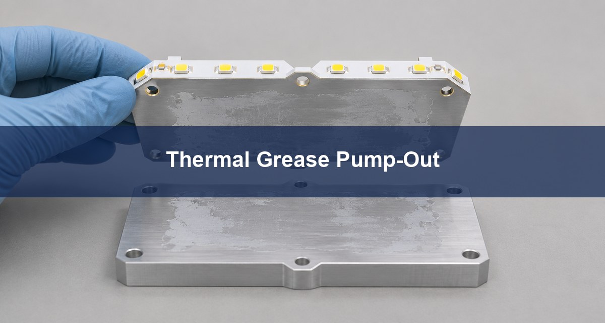
Thermal grease pump out
Repeated heating and cooling can change the gap between mating surfaces as they expand or warp. A mobile grease can move laterally as that gap changes and leave part of the hot area less well covered. Experimental work on thermal interface greases describes this degradation under cycling. The risk depends on the material and assembly, not just where paste is visible after disassembly.
Consider an LED driver on an aluminum-core board bolted to an enclosure. A uniform line of grease around the perimeter at first assembly can be ordinary squeeze-out. A growing temperature difference through the joint, paired with changed coverage in cycled samples, is stronger evidence. Opening a joint can disturb the imprint, so compare to an initial unit opened the same way.
Thermal paste dry out
Dry-out is a change in the paste’s condition, whereas pump-out is movement out of the active interface. They can occur together. A dry-looking area does not show how or when it developed. Review storage, operating temperature and time as well as cycling, and ask the supplier what evidence is appropriate for the material.
When the diagnosis matters, compare an unaged reference and a cycled unit. A separate time-at-temperature exposure, if agreed by the qualification team, can help distinguish changes driven by aging from those driven by repeated movement. Neither trial by itself proves the field failure mechanism.
Thermal interface material thickness
There is no universal bond-line thickness for PCB-to-heatsink joints. Measure or bound the assembled gap at its relevant locations, not just the dispensed layer or uncompressed sheet. For equal area and conductivity, a layer twice as thick has twice the ideal bulk thermal resistance, excluding contacts, spreading and voids.
For an illustrative 20 × 20 mm interface, assume 2 W/(m·K) and a uniform gap of 0.10 mm. The material-only estimate t/(kA) is 0.125 K/W. At 0.20 mm it is 0.250 K/W. These are model inputs, not product specifications. If the real joint bows, averaging the gap may hide a thick region under the device.
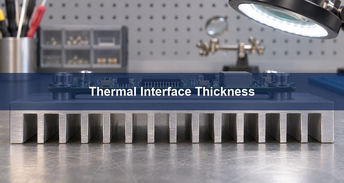
Thermal grease vs thermal pad
Use grease as a candidate for a thin, repeatable interface. A compliant pad can accommodate a larger tolerance stack, but its compressed thickness, contact resistance and force matter. Do not choose a pad only from its thermal conductivity rating or replace a required insulator with grease.
| Candidate | When to evaluate it | What to verify |
|---|---|---|
| Grease | Flat mating parts and a controlled thin joint. | Initially wetted area and performance after cycling. |
| Compliant pad | A tolerance gap that needs a resilient filler. | Compression, loading, thermal resistance and any required isolation rating. |
| Phase-change material | A controlled interface that reaches the material’s activation conditions. | Assembly instructions, initial conditioning and aged performance. |
Phase change thermal interface material
A qualified phase-change interface can soften through its designed temperature range and improve contact. It is not a universal solution for pump-out. Review the chosen product’s activation conditions, loading and thickness. If the interface never reaches the required temperature or the gap is too large, the candidate may not establish the intended contact.
Compare materials on independently assembled samples of the same board and enclosure. Do not interpret a later test on a reworked unit as a material-only comparison: cleaning, gap, fastening and assembly sequence may also have changed.
Thermal cycling test procedure
Choose a test that reproduces the movement and heat path of interest. External temperature cycling heats the assembly from its surroundings, whereas operating power cycles heat it from the active components. Document temperatures at relevant locations, fixture, clamp method, cycle count and inspection intervals. Do not substitute a generic cycle count for the intended service condition.
| Observation | Check next | What helps distinguish it |
|---|---|---|
| Hot from first startup | Gap, pressure and initial coverage. | Repeatable fresh assembly and flatness check. |
| Interface temperature difference grows with cycles | Coverage loss, gap changes and material aging. | Matched thermal measurements plus untouched reference units. |
| The enclosure is also hotter than before | Airflow, cooling load or mounting boundary. | Matched power, ambient and enclosure measurements. |
Thermal resistance measurement
Measure the assembly at stable, comparable power and cooling. Monitor points that bracket the interface when practical. State the sensor locations and whether the power used in the calculation represents heat through that path. If there are meaningful parallel paths, temperature difference divided by total power is an assembly comparison, not an isolated interface property.
ASTM D5470 provides a defined material test method for thermal transmission properties. It does not recreate the board flatness, fixture or duty cycle. Record both initial and aged behavior and apply the agreed thermal margin to the representative assembly.
Heatsink mounting pressure
Clamping pressure affects how the material wets or compresses and how wide the operating gap remains. Screw torque is not a pressure map: fastener friction, clamp spacing and board stiffness can change the load under the heat source. If a fresh assembly already runs hot, check enclosure flatness, fastener sequence and board support against the approved drawing before blaming material aging. Do not tighten beyond the approved limits.
Keep the same mounting conditions for candidate comparisons, and define the aged thermal result the assembly must meet. The aluminum PCB pad gap guide explains how to check the static fit; a fit check alone does not qualify the aged joint.
FAQ
Does grease at the edge prove pump-out?
No. It may have been squeezed out when assembled. Compare reference and aged samples.
Can higher conductivity fix a thick gap?
Not by itself. Thickness, contact resistance and coverage still matter.
Does tightening the screws always help?
No. It can change board bow or load. Follow the approved mounting requirements.
Is a dry-looking imprint conclusive?
No. Opening the joint may change it, and appearance cannot establish a cause.
Can a pad substitute for an electrical insulator?
Only when qualified for the required insulation and assembly conditions.
Should I compare temperatures at equal air temperature only?
No. Also match power, cooling, sensor positions and assembly conditions.
Can I approve a candidate using only its initial result?
Not if the risk is degradation during cycling. Measure after representative aging.
Can grease compensate for a warped board?
Do not assume so. Check the actual gap and the material’s qualified operating range.
Prepare an aluminum PCB thermal review
Send Best Technology the board stack, enclosure drawing, interface material and temperature records at sales@bestpcbs.com. Identify the initial and aged conditions so the board and assembly evidence can be reviewed separately.
You may also like




Tags: aluminum pcb, thermal cycling, Thermal Grease, Thermal Interface Materials