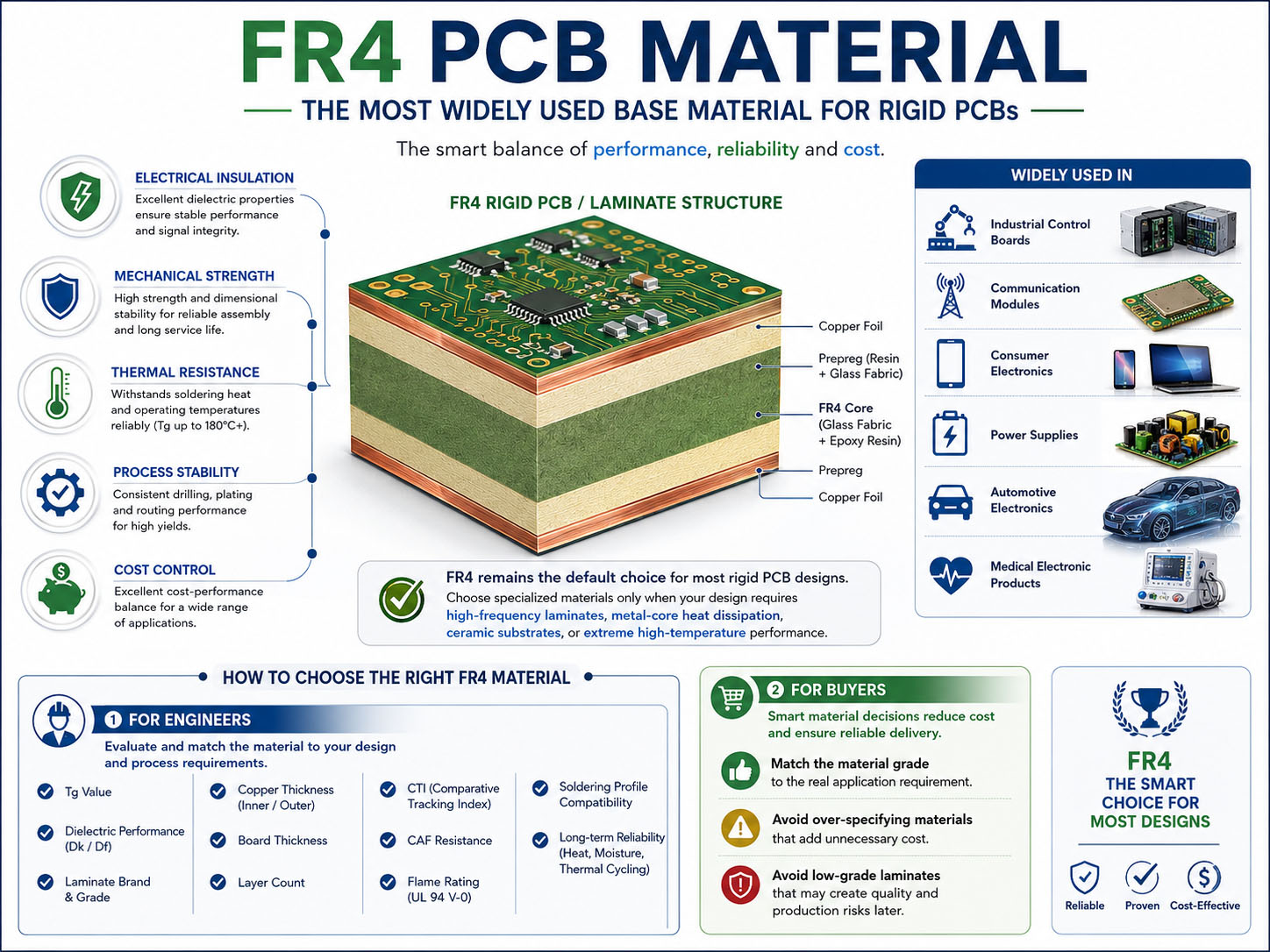
FR4 PCB material is the most widely used base material for rigid printed circuit boards because it offers a strong balance of electrical insulation, mechanical strength, thermal resistance, process stability, and cost control. For many industrial control boards, communication modules, consumer electronics, power supplies, automotive electronics, and medical electronic products, FR4 remains the default choice unless the design requires high-frequency laminates, metal-core heat dissipation, ceramic substrates, or extreme high-temperature performance.
For engineers, FR4 selection is not only about choosing standard FR4. The real decision involves Tg value, dielectric performance, laminate brand, copper thickness, board thickness, layer count, CTI, CAF resistance, flame rating, soldering profile, and long-term reliability. For buyers, the key is to match the material grade with the application requirement instead of paying for unnecessary specifications or accepting a low-grade laminate that may create production risks later.
What Is FR4 PCB Material?
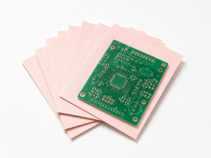
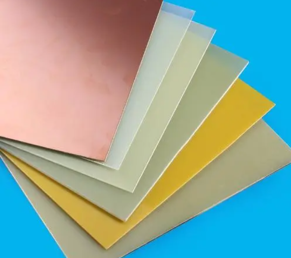
FR4 PCB material is a glass fiber reinforced epoxy laminate used as the insulating base of many printed circuit boards. “FR” means flame retardant, and “4” refers to a material classification based on woven glass cloth and epoxy resin. In PCB manufacturing, FR4 provides the mechanical platform that holds copper circuits, plated holes, solder mask, surface finish, and electronic components together.
| Structure | Function |
|---|---|
| Woven glass fiber | Provides mechanical strength and dimensional stability |
| Epoxy resin | Bonds the glass cloth and provides insulation |
| Copper foil | Forms the conductive circuit pattern |
| Prepreg | Bonds inner layers in multilayer PCB stack-ups |
| Core laminate | Provides stable thickness and copper-clad base material |
FR4 is popular because it works well with common PCB processes, including drilling, copper plating, lamination, imaging, etching, solder mask coating, surface finishing, SMT assembly, and reflow soldering. It is also available in many thicknesses, copper weights, Tg grades, and laminate brands, which makes it practical for both prototype and mass production.
Why Is FR4 PCB Material Important in PCB Manufacturing?
FR4 PCB material directly affects electrical performance, soldering reliability, mechanical strength, warpage control, insulation resistance, and long-term product stability. Even when two PCBs look similar on the outside, different FR4 grades can behave differently during lamination, drilling, plating, soldering, and field operation.
| Manufacturing Area | Why FR4 Selection Matters |
|---|---|
| Drilling | Poor material can cause smear, rough hole walls, or drill wear |
| Lamination | Tg and resin flow affect bonding and thickness control |
| Plating | Hole wall quality affects copper reliability |
| SMT reflow | Heat resistance affects delamination and warpage |
| Electrical testing | Dielectric quality affects insulation and leakage |
| Reliability testing | Material stability affects thermal cycling and humidity performance |
For simple low-voltage products, standard FR4 may be enough. For automotive electronics, industrial controllers, medical electronics, LED power boards, and communication equipment, the laminate must be selected with more care. A wrong material choice may not fail during prototype testing, but it can show problems during batch production, thermal cycling, humidity exposure, or long-term use.
How Does FR4 PCB Material Work?
FR4 works by combining glass fiber reinforcement with epoxy resin insulation. The glass fabric gives the board rigidity and dimensional control. The resin fills the glass weave, bonds the structure, and provides dielectric insulation between copper layers. Copper foil is bonded to the FR4 surface, then etched into circuit patterns.
In a multilayer PCB, FR4 cores and prepregs are stacked with inner copper layers. During lamination, heat and pressure make the prepreg resin flow and cure, bonding the full stack into one solid board. After lamination, the board is drilled, plated, patterned, solder masked, surface finished, and routed.
| Stage | Required Material Behavior |
|---|---|
| PCB fabrication | Stable during drilling, lamination, etching, and plating |
| PCBA assembly | Resistant to reflow soldering temperature and mechanical stress |
| End application | Stable under heat, humidity, voltage, vibration, and operating load |
This is why engineers often check Tg, Td, CTE, dielectric constant, dissipation factor, CTI, moisture absorption, and CAF resistance before confirming a material.
What Are the Main Properties of FR4 PCB Material?
FR4 PCB material has several core properties that define how it performs in production and use. These values vary by laminate brand and grade, so they should be confirmed from the actual datasheet before production.
| Property | Meaning | Typical Design Concern |
|---|---|---|
| Tg | Glass transition temperature | Heat resistance during reflow and operation |
| Td | Decomposition temperature | Material degradation under high heat |
| Dk | Dielectric constant | Signal speed and impedance control |
| Df | Dissipation factor | Signal loss, especially at higher frequencies |
| CTE | Coefficient of thermal expansion | Hole reliability and dimensional stability |
| CTI | Comparative tracking index | Surface insulation under voltage stress |
| Moisture absorption | Water uptake level | Reflow reliability and insulation stability |
| Peel strength | Copper bonding strength | Trace adhesion and durability |
| Flame rating | Fire resistance | Safety and compliance requirements |
For many standard FR4 materials, Dk is commonly around 4.2 to 4.8 depending on resin system, glass style, frequency, and test method. High-speed or impedance-sensitive designs should not rely on generic values. They should use laminate-specific data and controlled stack-up design.
What Types of FR4 PCB Material Are Commonly Used?
FR4 is not a single material grade. It includes several categories used for different performance levels and cost targets.
| FR4 Type | Typical Use |
|---|---|
| Standard FR4 | Consumer electronics, simple control boards, general products |
| Mid-Tg FR4 | Industrial products, improved thermal stability |
| High-Tg FR4 | Automotive, medical, industrial control, multilayer PCBs |
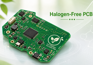
| Halogen-free FR4 | Products requiring lower halogen content |
| CAF-resistant FR4 | Dense multilayer boards, high-reliability applications |
| High-CTI FR4 | Power electronics and higher-voltage insulation designs |
| Low-Dk / low-loss FR4 | Higher-speed digital and communication boards |
| Lead-free compatible FR4 | Boards exposed to higher Pb-free reflow temperatures |
For many modern PCB projects, High-Tg FR4 is selected when the board has higher layer count, dense SMT assembly, lead-free soldering, long service life, or stricter reliability requirements. It gives better thermal margin during reflow and helps reduce risks such as delamination, barrel cracking, and dimensional instability.
Standard FR4 vs High-Tg FR4: What Is the Difference?
The main difference between standard FR4 and High-Tg FR4 is the glass transition temperature. Tg is the temperature range where the resin system changes from a glassy state to a softer rubbery state. Once the material passes this region, thermal expansion increases, and dimensional stability becomes harder to control.
| Item | Standard FR4 | High-Tg FR4 |
|---|---|---|
| Typical Tg Range | Around 130–140°C | Around 150–180°C or higher |
| Thermal Stability | Suitable for common electronics | Better for demanding reflow and operation |
| Cost | Lower | Higher |
| Layer Count Suitability | Better for simple boards | Better for multilayer and dense boards |
| Application Fit | Consumer, general control | Automotive, industrial, medical, communication |
| Reliability Margin | Moderate | Stronger thermal margin |
High-Tg FR4 is often preferred for 6-layer, 8-layer, 10-layer, and higher multilayer PCBs because lamination stress, copper distribution, drilling quality, and reflow exposure become more demanding. It is also useful when components have large thermal mass, when boards pass through multiple reflow cycles, or when the final product works in warm environments.
Which FR4 PCB Material Brands Are Common in PCB Production?
Different PCB manufacturers may use different laminate brands depending on customer requirements, certification needs, cost targets, and regional availability. Common FR4 laminate brands include Shengyi, Kingboard, ITEQ, Nan Ya, Isola, Panasonic, Ventec, and other qualified material suppliers.
| Brand | Common Positioning |
|---|---|
| Shengyi | Widely used in standard and High-Tg FR4 production |
| Kingboard | Common in cost-effective FR4 PCB manufacturing |
| ITEQ | Used for standard, High-Tg, and higher-performance laminates |
| Nan Ya | Used in multilayer and industrial PCB projects |
| Isola | Known for high-reliability and performance laminates |
| Panasonic | Used in advanced and high-reliability applications |
| Ventec | Offers High-Tg, thermal, and specialty materials |
| Rogers | Usually selected for RF/high-frequency laminates, not standard FR4 replacement |
For most FR4 PCB projects, the material brand should be confirmed before mass production. If the project requires UL recognition, automotive reliability, medical traceability, or long-term supply consistency, the exact laminate model should be specified in the drawing or fabrication notes.
How to Choose FR4 PCB Material for Different Applications?
Choosing FR4 PCB material should start from the actual working conditions, not only the unit price. A simple IoT board, an automotive control module, and a medical monitoring PCB may all use FR4, but their material requirements can be different.
| Application | Suggested FR4 Focus |
|---|---|
| Consumer electronics | Cost-effective standard FR4, stable basic performance |
| Industrial control | High-Tg FR4, good dimensional stability, reliable insulation |
| Automotive electronics | High-Tg, CAF resistance, thermal cycling performance |
| Medical electronics | Stable laminate source, documentation, traceability, clean process control |
| Communication equipment | Controlled Dk/Df, impedance stability, low-loss options if needed |
| Power supply boards | Copper thickness, CTI, insulation spacing, thermal margin |
| LED control boards | Heat resistance, copper weight, possible metal-core alternative if heat is high |
| Multilayer control boards | High-Tg material, stable lamination, controlled stack-up |
A practical selection method is to first define operating temperature, voltage, signal speed, layer count, copper weight, assembly profile, product lifetime, and compliance requirements. Then the PCB supplier can recommend a suitable FR4 grade and stack-up.
What Thickness and Copper Weight Are Used with FR4 PCB Material?
FR4 PCB thickness can range from very thin boards to thick power boards. Common finished thicknesses include 0.4 mm, 0.6 mm, 0.8 mm, 1.0 mm, 1.2 mm, 1.6 mm, 2.0 mm, and 2.4 mm. The most common finished thickness for many standard products is 1.6 mm, but compact electronics and multilayer boards often use thinner structures.
| Copper Weight | Typical Use |
|---|---|
| 0.5 oz | Fine lines, low-current circuits, compact designs |
| 1 oz | Standard signal and control boards |
| 2 oz | Higher-current paths and better thermal spreading |
| 3 oz and above | Power electronics, heavy copper designs, special current requirements |
FR4 thickness and copper weight must be considered together. Heavy copper requires wider spacing, stronger etching control, suitable solder mask thickness, and proper lamination design. Thin FR4 boards may need extra attention to warpage during SMT assembly, especially when copper distribution is uneven.
FR4 PCB Material vs Other PCB Materials
FR4 is versatile, but it is not always the best material for every PCB. Some projects require different substrates because of heat, frequency, flexibility, or mechanical requirements.
| Material | Main Advantage | Best-Fit Application |
|---|---|---|
| FR4 | Balanced cost, strength, insulation, process maturity | Most rigid PCB applications |
| High-frequency laminate | Lower signal loss and stable Dk | RF, antenna, microwave, high-speed communication |
| Aluminum PCB | Better heat dissipation than FR4 | LED lighting, power modules, thermal products |
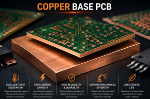
| Copper substrate PCB | Strong thermal and current handling | High-power electronics |
| Ceramic PCB | High thermal conductivity and excellent dimensional stability | Power modules, sensors, aerospace, medical, high-temperature circuits |
| Flexible PCB | Bendable and lightweight | Wearables, compact modules, dynamic connections |
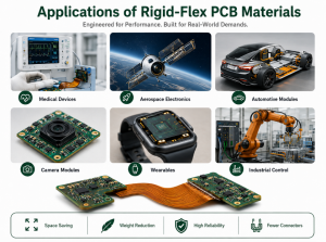
| Rigid-flex PCB | Combines rigid and flexible sections | Medical devices, aerospace, compact electronics |
FR4 is usually the first choice when the design does not have extreme thermal, RF, or mechanical bending requirements. If heat dissipation is the main challenge, aluminum, copper substrate, or ceramic PCB may be more suitable. If signal loss is critical at high frequencies, a low-loss laminate may be required.
What Standards and Tests Apply to FR4 PCB Material?
FR4 PCB material and finished boards are commonly evaluated through material datasheets, IPC standards, UL recognition, RoHS compliance, and factory quality control processes. The exact standard depends on the product market and application.
| Test / Standard Area | Purpose |
|---|---|
| UL 94 V-0 | Confirms flame retardant behavior |
| IPC-4101 | Defines laminate and prepreg material requirements |
| IPC-6012 | Covers rigid PCB performance and qualification |
| IPC-A-600 | Provides acceptability criteria for printed boards |
| IPC-TM-650 | Includes many PCB test methods |
| RoHS / REACH | Supports environmental compliance for global markets |
| Electrical test | Confirms open/short performance |
| Microsection analysis | Checks plating thickness, hole wall quality, and laminate condition |
| Thermal stress test | Evaluates heat resistance and interconnect reliability |
| Solderability test | Confirms surface finish readiness for assembly |
For high-reliability projects, material traceability is important. Buyers should request laminate brand, material model, UL file information if needed, stack-up confirmation, copper thickness, surface finish, impedance report, and test records according to the application.
Common FR4 PCB Material Problems and Failure Analysis
Many FR4 PCB failures are not caused by the base material alone. They often come from the mismatch between material selection, PCB design, fabrication process, assembly profile, and product environment.
| Problem | Possible Cause | Practical Prevention |
|---|---|---|
| Delamination | Low thermal resistance, moisture, poor lamination | Use suitable Tg, bake when needed, control lamination |
| Warpage | Uneven copper distribution, thin board, high heat | Balance copper, optimize stack-up, control panel design |
| Barrel cracking | High CTE stress, poor plating, thermal cycling | Use reliable material, proper hole plating, thermal testing |
| CAF risk | Dense spacing, humidity, voltage stress | Select CAF-resistant material, improve spacing and cleanliness |
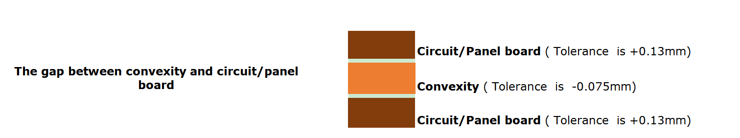
| Poor impedance control | Unstable Dk, inaccurate stack-up | Use laminate datasheet values and controlled stack-up |
| Solder mask cracking | Heavy copper, thermal stress, process mismatch | Adjust solder mask process and copper design |
| Insulation failure | Contamination, moisture, poor spacing | Improve cleaning, material selection, and creepage design |
In factory review, engineers usually check the Gerber data, stack-up, drill chart, copper balance, minimum spacing, impedance requirement, assembly temperature profile, and working environment before confirming the FR4 specification. This helps prevent avoidable problems before production starts.
How Does FR4 PCB Material Affect PCB Cost?
FR4 PCB cost is affected by laminate grade, thickness, copper weight, layer count, board size, surface finish, tolerance, testing requirements, and production volume. The material itself is only one part of the total PCB cost, but it can influence several process costs.
| Cost Factor | Impact on Price |
|---|---|
| High-Tg material | Higher laminate cost, better thermal margin |
| Special brand requirement | May increase cost and lead time |
| Thick copper | More etching difficulty and process control |
| Thin board | More handling and warpage control |
| Multilayer stack-up | More lamination steps and inspection |
| Impedance control | Requires stack-up engineering and testing |
| Tight tolerance | Increases manufacturing control cost |
| Special testing | Adds inspection time and documentation |
The best way to control cost is not to choose the cheapest FR4. It is to choose the right material grade for the actual risk level. For example, using High-Tg FR4 on a high-density industrial controller may reduce assembly and field reliability risks. For a simple low-temperature consumer board, standard FR4 may be more economical.
FR4 PCB Material Case Study: 8-Layer Industrial Control Board
A customer needed an 8-layer FR4 PCB for an industrial control system. The board included fine-pitch ICs, controlled impedance traces, multiple power domains, and dense via distribution. The product would operate inside a control cabinet where ambient temperature could rise during long working cycles.
The first cost-driven option used standard Tg FR4. During engineering review, the main risks were multilayer lamination stability, reflow thermal stress, impedance consistency, and long-term operation under warm conditions. The material was then upgraded to High-Tg FR4, with a controlled stack-up and balanced copper distribution.
| Item | Engineering Decision |
|---|---|
| Layer count | 8 layers for routing density and power integrity |
| Material | High-Tg FR4 for better thermal margin |
| Surface finish | ENIG for fine-pitch assembly and storage stability |
| Thickness | Controlled finished thickness for mechanical fit |
| Impedance | Verified through stack-up and test coupon |
| Inspection | AOI, electrical test, microsection, and final quality check |
The final solution improved process confidence without moving to an expensive specialty laminate. This is a common engineering decision: use a better FR4 grade when the design needs reliability, but avoid over-specifying material when FR4 already meets the project requirement.
What Should Be Checked Before Ordering FR4 PCBs?
Before placing an FR4 PCB order, engineering and purchasing teams should confirm both technical and commercial details. This avoids quotation gaps, production delays, and material substitutions.
- FR4 material grade and Tg requirement
- Laminate brand or approved alternatives
- Finished board thickness and tolerance
- Copper weight for inner and outer layers
- Layer count and stack-up structure
- Minimum trace width and spacing
- Minimum hole size and aspect ratio
- Impedance control requirement
- Surface finish, such as HASL, OSP, ENIG, or immersion silver
- Solder mask color and silkscreen requirement
- UL, RoHS, REACH, or other compliance needs
- Testing requirements, including electrical test, AOI, impedance, microsection, or reliability testing
- Panelization, fiducials, tooling holes, and assembly edges
- Production quantity, delivery schedule, and documentation requirements
For regulated or long-life products, buyers should also ask whether the supplier can provide material traceability, batch records, inspection reports, and stable material sourcing for repeat orders.
How to Choose a Reliable FR4 PCB Material Manufacturer?
A reliable FR4 PCB manufacturer should do more than produce boards from supplied Gerber files. The supplier should understand material behavior, stack-up design, DFM review, drilling control, lamination quality, surface finish selection, and assembly requirements.
| Supplier Capability | Why It Matters |
|---|---|
| DFM review | Finds design risks before fabrication |
| Stack-up engineering | Supports impedance, thickness, and layer reliability |
| Material traceability | Helps regulated and repeat-production projects |
| Quality system | Supports stable manufacturing control |
| Testing capability | Confirms electrical, mechanical, and process quality |
| PCBA support | Ensures PCB design fits assembly needs |
| Component sourcing | Helps turnkey projects reduce coordination work |
| Production experience | Reduces avoidable process mistakes |
A China source factory can be a practical choice for global buyers when it offers real manufacturing capability, clear communication, engineering support, quality documentation, and stable export experience. The key is to verify the actual capability instead of relying only on a low quote.
Best Technology supports FR4 PCB fabrication, multilayer PCB production, High-Tg FR4 boards, impedance-controlled PCB manufacturing, component sourcing, PCBA assembly, DFM review, testing, and turnkey electronics manufacturing for global customers. For projects that need engineering support from prototype to volume production, early material review can reduce cost and improve production stability.
FAQ About FR4 PCB Material
What does FR4 mean in PCB material?
FR4 means flame-retardant glass fiber reinforced epoxy laminate. It is the most common base material for rigid PCBs. The woven glass cloth provides strength, while the epoxy resin provides insulation and bonding. It is widely used because it balances performance, manufacturability, and cost.
Is FR4 PCB material suitable for high-temperature applications?
FR4 can support many applications with moderate thermal requirements, especially when High-Tg FR4 is used. For continuous high-temperature operation, repeated severe thermal cycling, or very high power density, engineers should evaluate High-Tg FR4, metal-core PCB, ceramic PCB, or another specialty material.
What is the difference between standard FR4 and High-Tg FR4?
Standard FR4 usually has a lower glass transition temperature, while High-Tg FR4 provides better thermal stability. High-Tg material is often used for multilayer PCBs, lead-free assembly, automotive electronics, industrial control boards, and products that need stronger reliability margins.
Can FR4 be used for multilayer PCBs?
Yes. FR4 is widely used for 4-layer, 6-layer, 8-layer, 10-layer, and higher multilayer rigid PCBs. For higher layer counts, High-Tg FR4 and a controlled stack-up are usually recommended to improve lamination stability, drilling quality, impedance control, and reflow reliability.
Is FR4 good for high-frequency PCB design?
FR4 can be used for some moderate-speed and controlled-impedance designs, but it may not be ideal for high-frequency RF, microwave, or very low-loss applications. For those projects, engineers often choose Rogers, PTFE-based, hydrocarbon ceramic, or other low-loss laminates.
What is the common thickness of FR4 PCB?
Common FR4 PCB thicknesses include 0.8 mm, 1.0 mm, 1.2 mm, 1.6 mm, and 2.0 mm. A 1.6 mm board is common for many standard products. Thinner or thicker boards are selected based on mechanical space, connector fit, impedance, copper weight, and assembly needs.
Does FR4 PCB material absorb moisture?
FR4 can absorb a small amount of moisture. If moisture is trapped inside the board and exposed to high reflow temperature, it may increase the risk of delamination or blistering. Proper storage, baking when needed, and suitable laminate selection help reduce this risk.
What copper weight is used with FR4 PCB material?
Common copper weights include 0.5 oz, 1 oz, and 2 oz. Higher copper weights are used for power electronics and high-current circuits. Heavy copper FR4 boards require more careful spacing, etching control, solder mask design, and thermal management review.
Is FR4 PCB material flame retardant?
FR4 is designed as a flame-retardant laminate, and many FR4 materials meet UL 94 V-0 requirements. For certified products, buyers should confirm the actual laminate model, UL file information, and finished board compliance requirements with the PCB manufacturer.
Can FR4 PCB material be used for automotive electronics?
Yes, FR4 is used in many automotive electronic boards. However, automotive projects often require High-Tg FR4, stable material traceability, strict process control, thermal cycling review, and compliance with relevant quality requirements. Material selection should match the actual application environment.
Why does FR4 PCB material cost vary between suppliers?
Cost varies because suppliers may use different laminate brands, Tg grades, copper weights, process controls, testing levels, and documentation standards. A lower quote may not include the same material grade, inspection depth, or traceability. Always compare the full specification, not only the unit price.
How do I know which FR4 grade my PCB needs?
Start with the product’s layer count, operating temperature, voltage, signal speed, assembly profile, copper thickness, lifetime, and industry requirements. For simple electronics, standard FR4 may work well. For dense, high-reliability, or thermally demanding boards, High-Tg or specialty FR4 is often safer.
Conclusion
FR4 PCB material remains the practical foundation for most rigid PCB designs because it combines insulation, mechanical strength, process maturity, thermal performance, and cost efficiency. The key is to select the correct FR4 grade instead of treating all FR4 laminates as equal. Tg, copper weight, thickness, Dk/Df, CTI, CAF resistance, laminate brand, stack-up design, and testing requirements all affect final performance.
For engineers, the best choice is the material that supports electrical stability, assembly reliability, and application life. For buyers, the best choice is the supplier that can provide clear material recommendations, controlled production, reliable inspection, and repeatable quality from prototype to batch production.