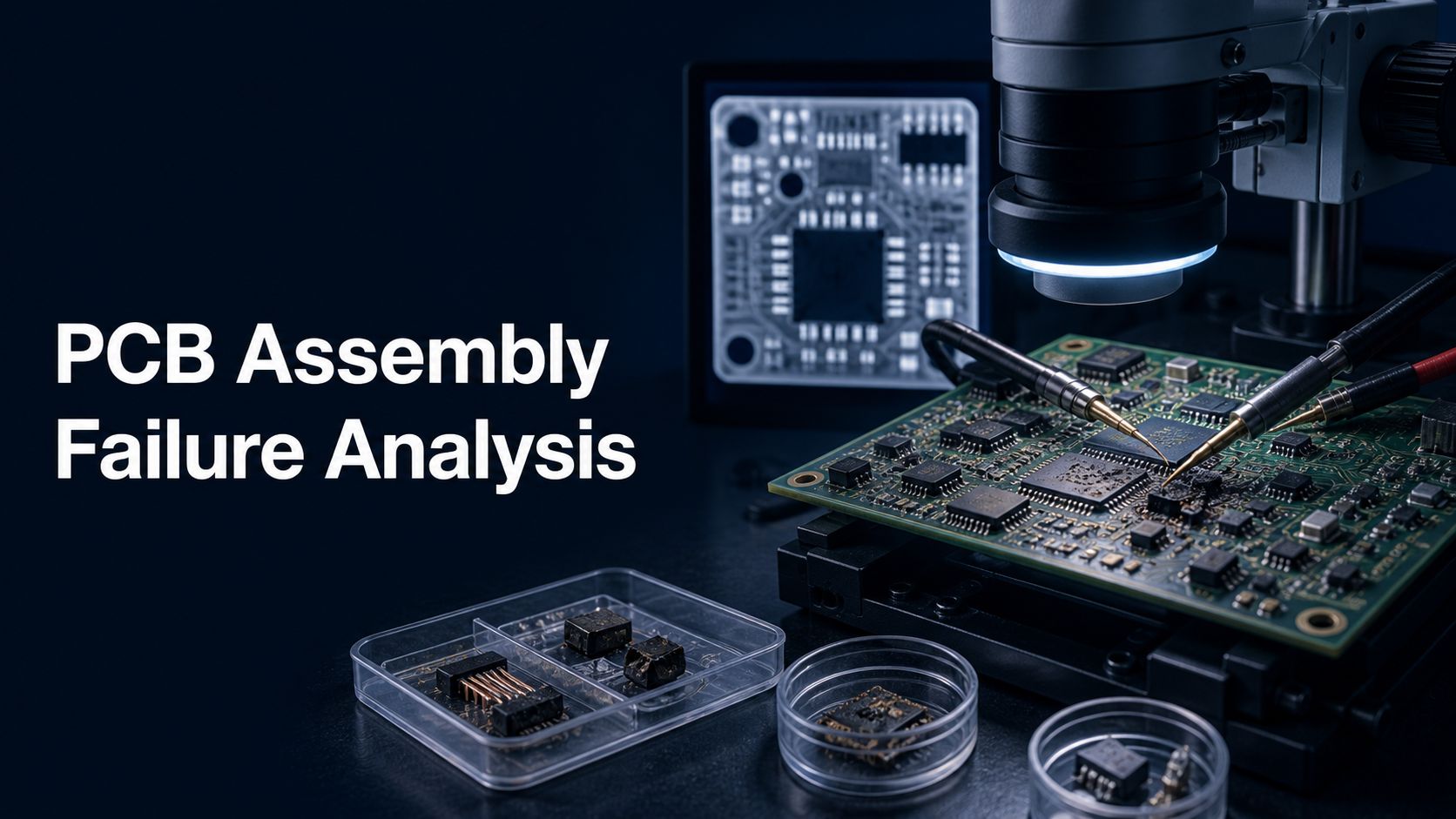
A PCB assembly failure analysis service should deliver more than a list of possible defects. It should protect the evidence, reproduce the reported symptom, select the least destructive checks first, distinguish design, process, component, firmware, and fixture causes, and show why the final root-cause conclusion fits the evidence.
The investigation scope depends on the symptom, sample quantity, product history, available records, acceptable destructive work, and decision the customer must make. This guide explains how to prepare a failure-analysis RFQ and how to judge whether the resulting report can support containment and corrective action.
Can the investigation prove why the PCBA failed without destroying the only useful evidence too early?
Before cleaning, reworking, powering, updating firmware, or removing parts, record the as-received state and agree on the test sequence. An uncontrolled first action can erase residue, thermal evidence, intermittent behavior, solder condition, or software state.
EBest Circuit can review the build files, manufacturing records, symptom description, failed samples, and requested deliverables before confirming project-specific support.
Send Gerber or ODB++, BOM, CPL, schematic where permitted, firmware and checksum, test logs, serial/lot history, photos, environmental history, known-good samples, failure rate, allowed destructive methods, and required report. Specialized laboratory methods must be confirmed for the actual case rather than assumed.
What a PCB Assembly Failure Analysis Service Must Deliver
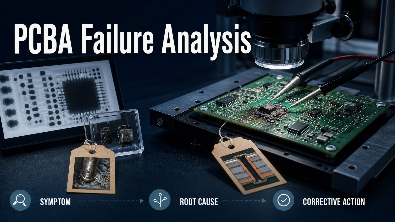
The service should connect symptom, evidence, mechanism, root cause, affected population, and corrective action. A useful report states what was received, how samples were identified, which checks were performed, what each result means, which hypotheses were eliminated, and what additional uncertainty remains.
The final conclusion should be proportional to the evidence. “Possible solder issue” may be a screening observation; it is not a root cause. Root cause explains the condition and the process, design, material, software, or handling path that created it.
Preserve the Failed Unit Before Evidence Is Lost
Treat every returned board as evidence. Photograph packaging and the as-received unit, record serial number and revision, protect electrostatic-sensitive parts, preserve contamination, and document any mechanical damage or signs of prior repair.
Do not automatically clean, bake, power, reflash, reseat connectors, or touch suspect joints. Define who may operate the sample and under what safe conditions. If the unit is hazardous, burned, swollen, wet, or mechanically compromised, isolate it and apply an appropriate safety plan before analysis.
Define the Symptom and Reproduce It Safely
A precise symptom is the investigation’s first measurement. Record operating state, input voltage, load, temperature, communication, timing, firmware, peripherals, mechanical position, and failure signature. “Board dead” is insufficient if the actual observation is an overcurrent trip after a specific command.
Reproduction should use current limits, monitored rails, controlled fixtures, and an approved sequence. Compare the failed unit with a known-good unit under the same conditions. If the fault is intermittent, record frequency and triggers rather than repeatedly stressing the board until a new failure is created.
Build a Timeline From Manufacturing and Field Records
The failure timeline can reveal what the physical sample cannot. Connect component lots, PCB lot, assembly revision, process history, inspection, programming, test, rework, shipment, installation, usage, and field event.
The PCB assembly traceability requirements guide explains how unit identity supports this lookup. Compare failures by lot, date, line, program, supplier, component, location, operating hours, and symptom. A cluster can identify a population at risk before the laboratory work is complete.
Start With Visual, Electrical, and Non-Destructive Checks
Begin with methods that preserve the sample for later tests. Useful early work may include external visual inspection, microscopy, resistance and diode-mode comparisons, controlled power observation, thermal imaging, current signature, connector checks, optical inspection, and suitable imaging.
Review the existing production evidence before generating new data. The AOI guide shows what visible assembly information may already exist. Note that a passed production test only proves the conditions and limits executed at that time.
Separate Design, Process, Component, Firmware, and Fixture Causes
Organize hypotheses by cause family to avoid blaming the first visible anomaly. A burned component may be the result of an upstream short, incorrect power sequence, firmware command, fixture connection, contamination, or inadequate thermal margin.
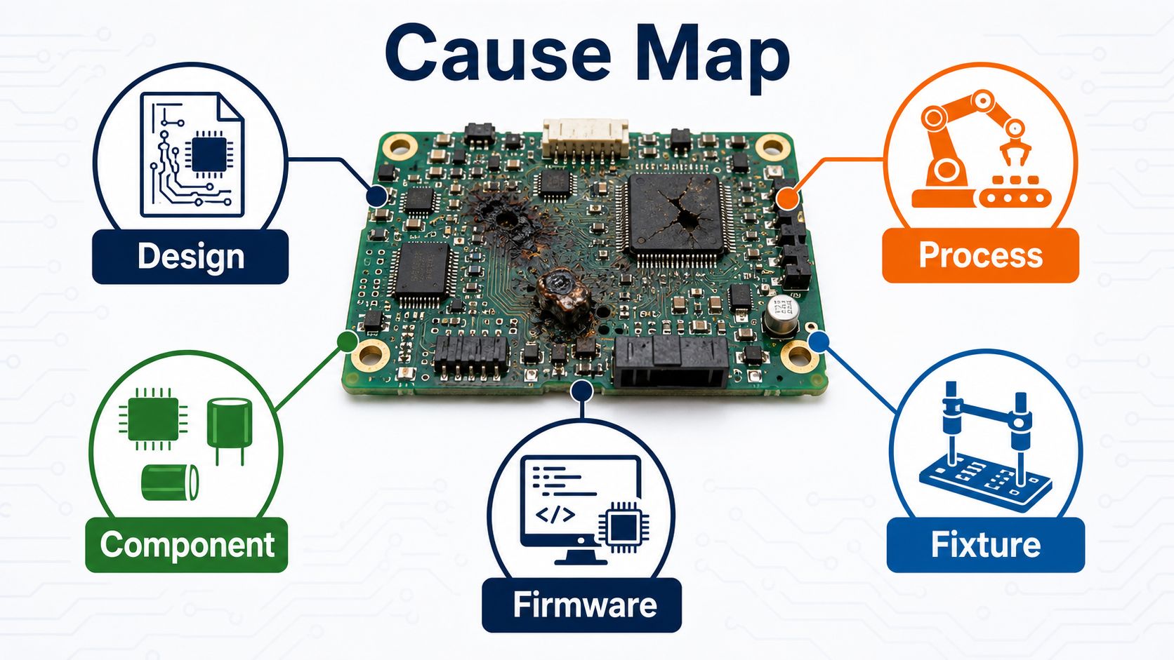
| Cause Family | Evidence to Compare | Typical Control Question |
| Design | Margins, startup, loads, protection, layout, thermal path | Can the same symptom be produced on known-good hardware? |
| Process | Inspection, profiles, recipes, handling, contamination, repair | Does the finding cluster by lot, station, or operation? |
| Component | Lot, source, value, damage, electrical behavior | Is the part cause, contributor, or casualty? |
| Firmware | File, checksum, configuration, logs, sequence | Does a controlled software state change the symptom? |
| Fixture/system | Cables, contacts, loads, instruments, peripherals | Does the failure follow the board or the setup? |
Use X-Ray and Imaging for Hidden Assembly Evidence
Imaging can examine joints or structures that are not visible from the surface. The question should identify the package, interface, defect mechanism, view, comparison sample, and acceptance basis. Imaging alone may show an anomaly without proving electrical consequence.
The automated X-ray inspection guide explains hidden-joint planning. For failure analysis, correlate images with electrical location, symptom, design geometry, known-good boards, and later physical evidence when authorized.
Authorize Cross-Section or Other Destructive Work Carefully
Destructive analysis should answer a specific question that non-destructive work cannot resolve. Mark the target, record the pre-cut condition, define orientation and depth, preserve reference samples, and agree on custody of the remaining material.
Do not section the only failed joint simply because a laboratory method is available. First confirm that location correlates with the symptom and that the customer accepts losing the original structure. Record preparation artifacts separately from true failure features.
Correlate Findings Across Failed and Known-Good Units
A comparison set prevents normal variation from being labeled a defect. Include failed units with the same symptom, failed units with different symptoms, known-good units from the affected lot, and known-good units from a stable baseline when available.
Keep identities and histories separate. If all samples are pooled or unlabeled, the investigation cannot connect a physical finding to production condition or field behavior. Sample selection should support the decision, not merely increase count.
Prove Root Cause Instead of Listing Possibilities
Root cause requires converging evidence. The proposed mechanism should explain the symptom, location, timing, affected population, physical evidence, and comparison results. A confirmation test, controlled recreation, design calculation, process correlation, or targeted experiment may strengthen the conclusion.
Separate confirmed root cause from contributing factor and unverified hypothesis. Also state limitations: unavailable records, altered samples, insufficient quantity, intermittent behavior, or methods outside scope.
Contain the Affected Lot While Analysis Continues
Do not wait for a final report before controlling a credible risk. Identify potentially affected lots or serial ranges, hold unshipped material, preserve samples and records, define temporary screening, and communicate the containment boundary.
Temporary screening is not permanent corrective action. It should have a documented detection limit, false-pass risk, ownership, release authority, and exit condition. The PCBA test-plan guide helps define executable screens and evidence.
Turn Root Cause Into Corrective and Preventive Action
Corrective action must change the condition that created the failure. Actions may affect design, material, supplier control, work instruction, process recipe, handling, fixture, firmware, inspection, test, or change management.
Define owner, implementation date, affected revisions, verification method, sample size, acceptance criteria, and effectiveness review. The action is incomplete if the team cannot show that the failure mechanism was removed or reduced and that no new risk was introduced.
Preserve the evidence before rework changes the failure.
Send the failed-unit identity, symptom, build files, manufacturing and test records, firmware, field history, photos, known-good comparison, sample count, destructive-analysis limits, and required decision. EBest Circuit can review the package and confirm the next project-specific step.
Samples | Symptom | Records | Firmware | Limits | Report | Decision
Define the Failure Analysis Report and Evidence Package
Specify the report before the investigation begins. Request sample inventory, as-received photographs, procedure, equipment or method identification as applicable, raw observations, annotated images, electrical data, comparisons, hypothesis table, conclusion strength, limitations, and corrective-action recommendations.
Decide whether physical samples, sections, removed parts, images, and electronic data must be returned. Link every result to the correct sample identity and record revision.
Compare Scope, Sample Needs, Lead Time, and Exclusions
Quotations are comparable only when they investigate the same question. Normalize intake review, reproduction work, included non-destructive methods, destructive authorization, sample quantity, known-good comparisons, engineering hours, external laboratory work, report level, meetings, shipping, and exclusions.
Ask how additional work is approved if the initial evidence is inconclusive. A low entry price may cover inspection only, while a higher quote may include controlled reproduction, hypothesis testing, and an actionable report.
Send a Failure Analysis RFQ That Can Be Executed
Package the investigation like a controlled engineering job. Include unit and lot identities, revisions, symptom, operating conditions, failure frequency, safety concerns, manufacturing/test records, design files, firmware, field history, prior interventions, sample list, known-good baseline, allowed destructive methods, required conclusion, report format, and deadline.
If lead-free soldering or thermal history is relevant, include solder alloy, paste, profiles, repair history, and handling conditions; the lead-free PCB assembly guide provides useful process context.
PCB Assembly Failure Analysis Service FAQ
What is PCBA failure analysis?
It is a controlled investigation that links a board-level symptom to evidence, failure mechanism, root cause, affected population, and corrective action.
Should a failed board be reworked before analysis?
Usually not until the as-received state is documented and the plan is approved. Rework can remove the evidence needed to explain the failure.
Why start with non-destructive methods?
They preserve the unit for later comparisons and targeted destructive work. The sequence should move from broad, evidence-preserving checks to focused confirmation.
Does an X-ray anomaly prove root cause?
No. It must correlate with the electrical symptom, location, comparison units, and an accepted failure mechanism.
How many samples are needed?
It depends on failure variation, rate, available evidence, and decision. Provide multiple failed and known-good units when possible.
What is the difference between failure mode and root cause?
Failure mode describes how the unit failed; root cause explains the condition and path that created that failure.
Can firmware cause an apparent assembly failure?
Yes. Firmware, configuration, programming, and fixture behavior can produce symptoms that resemble hardware defects, so they must be controlled.
What records help the investigation?
Unit genealogy, component lots, revisions, process records, inspection, programming, test logs, rework, shipment, and field history can narrow the affected population.
What should a failure-analysis report include?
It should include sample identity, methods, observations, comparisons, eliminated hypotheses, conclusion, evidence strength, limitations, and corrective recommendations.
Can EBest Circuit promise a specific laboratory method before review?
No. EBest Circuit can review the package and confirm project-specific support, sample needs, and whether specialized external analysis is required.
Turn a failed PCBA into a controlled root-cause investigation.
Email the failed-sample list, symptoms, build files, records, firmware, known-good comparison, field history, analysis limits, report requirement, and target date. EBest Circuit will review the evidence and confirm a project-specific path and quotation scope.
Failed units | Known-good | Files | Records | Firmware | Report | Deadline