PCB manufacturing PCB manufacturing
Home > Blog

aluminum core PCB

Best Aluminum PCB Manufacturer in China | Custom MCPCB Fabrication & Assembly
Saturday, November 7th, 2026

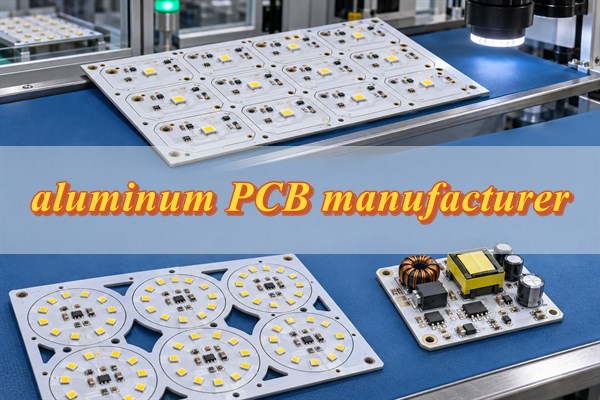
Looking for a reliable aluminum PCB manufacturer in China? EBest Circuit provides custom MCPCB fabrication, SMT and through-hole assembly, and prototype-to-mass-production services for LED lighting, power electronics, automotive, and industrial applications.

Whether you need bare aluminum circuit boards or assembled MCPCBs, we provide a free DFM check to review manufacturing feasibility before production. Compare the manufacturing capabilities, quality certifications, lead times, and quotation requirements below to determine whether the service fits your project.
aluminum PCB manufacturer, https://www.bestpcbs.com/blog/2026/11/aluminum-pcb-manufacturer-2/

What Types of Aluminum PCBs Can EBest Circuit Manufacture?

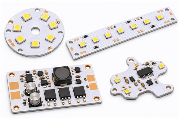
EBest Circuit manufactures single-layer, double-sided, and selected multilayer aluminum PCBs, including custom-shaped metal-backed circuit boards. The suitable construction depends on circuit complexity, thermal management, electrical insulation, and mechanical requirements.
aluminum PCB manufacturer, https://www.bestpcbs.com/blog/2026/11/aluminum-pcb-manufacturer-2/
  • Single-layer aluminum PCB: Combines a copper circuit layer, thermally conductive dielectric, and aluminum base. It is commonly used in LED lighting modules, power electronics, and high-power LED applications.
  • Double-sided aluminum PCB: Supports additional circuit routing and component connections. Electrical isolation between the conductors and aluminum substrate must be maintained through a suitable construction.
  • Multilayer aluminum PCB: Combines multiple circuit layers with a metal-backed structure for applications requiring higher circuit density and heat dissipation. Feasibility depends on the stackup, dielectric isolation, and interconnection requirements.
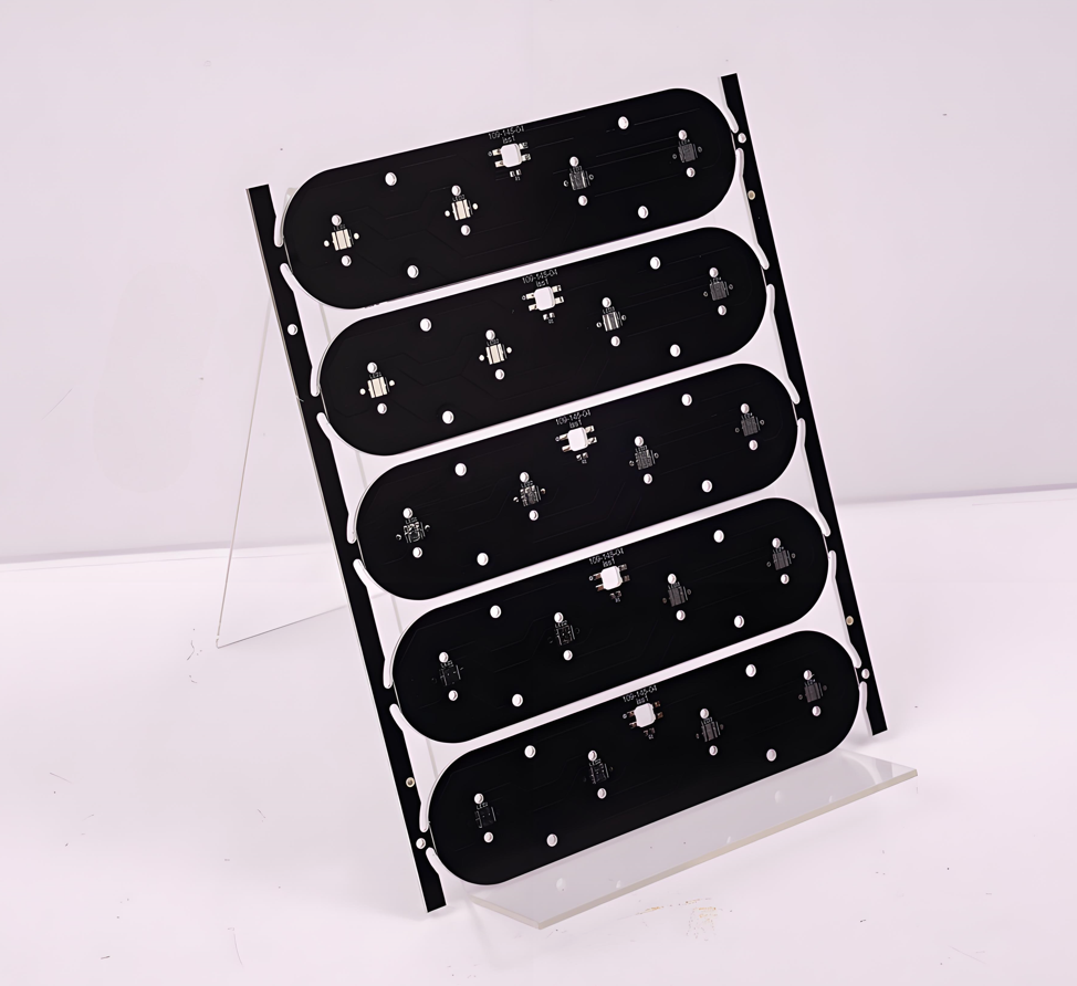
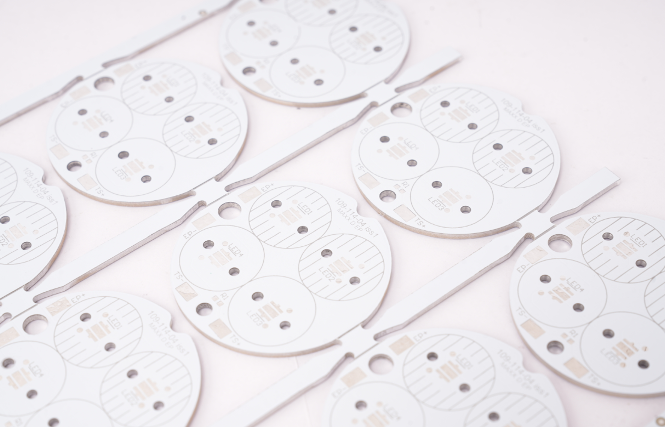
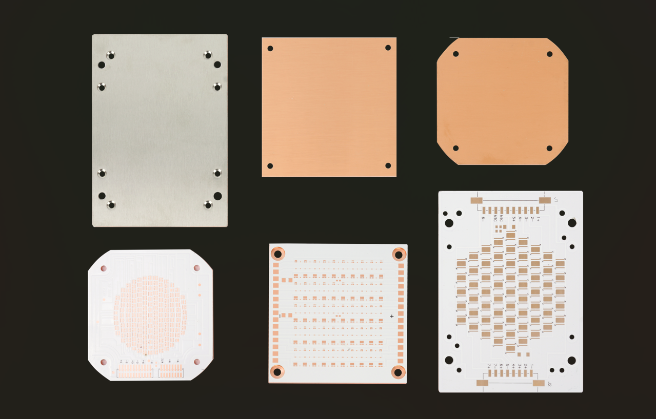
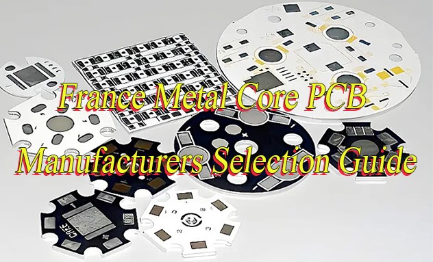
  • Custom-shaped aluminum PCB: Circular, rectangular, linear, and irregular circuit boards can be produced with mounting holes, slots, and custom outlines according to approved mechanical drawings.

Aluminum core PCB, aluminum base PCB, aluminum substrate PCB, and aluminum-backed PCB are common sourcing terms. Their constructions may differ, so customers should specify the required stackup when requesting a quotation.

Before selecting a type, confirm the released layer structure, insulation route, outline, and mounting interface; the product name alone cannot verify manufacturability.

What Are EBest Circuit’s Aluminum PCB Manufacturing Capabilities?

EBest Circuit supports custom aluminum PCB fabrication across a broad range of metal substrates, copper thicknesses, dielectric materials, and mechanical features. Use the capability references below for preliminary screening; the combined design still requires engineering review.

These values are screening boundaries, not automatic approval. Confirm the complete stackup and tolerance combination because one individually acceptable feature can still create a fabrication risk when combined with others.

Manufacturing Specification EBest Circuit Capability
Layer Count 1–10 layers for applicable MCPCB structures
Aluminum Base Material 1060, 3003, 5052, 6061
Board Thickness 0.8–5.0 mm across listed MCPCB processes
Maximum Board Size Up to 610 × 1,625 mm
Copper Thickness 0.5–10 oz across applicable constructions
Minimum Trace Width / Spacing 0.15 / 0.15 mm; finer features subject to review
Minimum Hole Diameter 0.80 mm in the standard MCPCB catalog
Minimum Hole Spacing 1.00 mm in the standard MCPCB catalog
CNC Outline Tolerance ±0.15 mm
Dielectric Thermal Conductivity 1.0–8.0 W/m·K across available material options
Surface Finish Confirm per MCPCB construction; options can include ENIG, ENEPIG, lead-free HASL, OSP, immersion silver, and immersion tin

These values are individual process references, not a promise that every extreme can be combined. Final manufacturability depends on the complete stackup, material combination, copper thickness, board dimensions, surface finish, and required tolerances.

What Aluminum PCB Assembly Services Does EBest Circuit Provide?

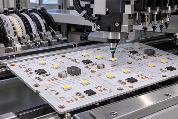
EBest Circuit offers bare aluminum PCB fabrication and assembled MCPCB services, allowing customers to source circuit boards, components, and assembly from one manufacturer.
aluminum PCB manufacturer, https://www.bestpcbs.com/blog/2026/11/aluminum-pcb-manufacturer-2/
  • Component sourcing: LEDs, MOSFETs, power ICs, resistors, capacitors, connectors, and other components can be procured according to the approved BOM.
  • SMT assembly: Automated component placement and reflow soldering support compatible surface-mounted devices, including LEDs and power semiconductors.
  • Through-hole assembly: Connectors, terminals, and leaded components can be installed and soldered using an appropriate process.
  • Mixed-technology assembly: SMT and through-hole components can be integrated where the aluminum PCB construction supports the required process sequence.
  • Assembly inspection: AOI and visual inspection can identify component misalignment, polarity errors, missing components, and visible solder-joint defects.
  • Functional testing: Electrical and operational testing follows customer-provided procedures and acceptance criteria.

Aluminum PCB assembly requires a controlled soldering profile. Because the metal substrate spreads heat away from solder joints, the profile must provide sufficient thermal input without exceeding the limits of the dielectric material or components.

Customers can order bare aluminum PCBs or fully assembled MCPCBs, depending on their manufacturing and delivery requirements.

What Are the Common Aluminum PCB Manufacturing Challenges and Solutions?

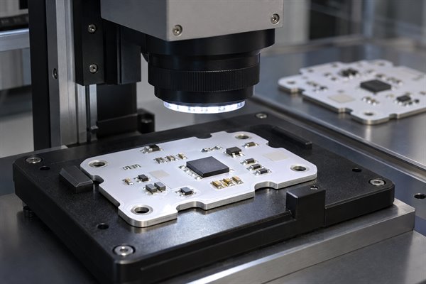
Aluminum PCB fabrication requires coordinated control of dielectric insulation, board flatness, copper processing, and mechanical accuracy. These factors directly affect manufacturing yield, assembly compatibility, and finished-board reliability.
aluminum PCB manufacturer, https://www.bestpcbs.com/blog/2026/11/aluminum-pcb-manufacturer-2/
  • Prevent dielectric insulation failure: Drilling and routing can damage the insulation between copper circuitry and the aluminum substrate. Controlled machining and appropriate insulation verification help prevent electrical shorts.
  • Control board warpage: Material stress and processing temperatures can affect flatness, especially on large or thin metal-backed boards. Suitable materials, process control, and dimensional inspection help maintain the required tolerances.
  • Allow for heavy-copper etching: Thick copper makes narrow traces and conductor spacing more difficult to manufacture. Copper weight, trace geometry, and etching allowances must be evaluated together to maintain conductor accuracy.
  • Verify holes and outlines: Inaccurate holes, metal burrs, and poorly controlled outlines can interfere with enclosure or heat-sink installation. Controlled drilling, CNC routing, deburring, and dimensional inspection reduce these risks.
  • Protect multilayer isolation: Complex metal-backed constructions require reliable isolation between electrical conductors and the aluminum substrate. Stackup verification and process control help prevent unintended electrical connections.

For nonstandard MCPCBs, a free DFM check before fabrication can identify manufacturing conflicts before material release, reducing avoidable revisions, material waste, and production delays.

What Quality Certifications Does EBest Circuit Hold for Aluminum PCB Manufacturing?

EBest Circuit lists quality-management certifications and recognitions that support PCB manufacturing and assembly for applicable industrial, automotive, medical, and aerospace-related electronics projects. Buyers should verify the current certificate holder, covered site, scope, and validity against the proposed order.

  • ISO 9001:2015: Supports standardized production processes, corrective actions, quality management, and continual improvement.
  • ISO 13485:2016: Provides a quality-management framework relevant to medical-device manufacturing and associated supply chains.
  • IATF 16949: Supports automotive quality-management requirements for applicable certified operations.
  • AS9100D: Addresses aerospace quality-management requirements for applicable manufacturing activities.
  • UL recognition: Provides product recognition and safety-related documentation for PCB constructions covered by the applicable recognition.

Request the relevant certificates before production and confirm that their identity and scope match the manufacturing route for your order. A certificate name alone does not establish that every facility, process, or product construction is covered.

Use only current, scope-matched documents for supplier approval; an expired or mismatched certificate creates a qualification risk even when the standard name appears relevant.

What Is the Lead Time for Aluminum PCB Prototypes and Mass Production?

Aluminum PCB lead time depends on layer count, material availability, manufacturing complexity, and order quantity. EBest Circuit offers standard and expedited production options for eligible MCPCB prototype orders.

Production Type Standard Lead Time Fastest Service
Single-Layer Aluminum PCB Prototype 4 days 24 hours
Two-Layer Aluminum PCB Prototype 14 days 7 days
Four-Layer Aluminum PCB Prototype 21 days Confirm per project
PCB Assembly 1 week 2 days
Mass Production Based on order specifications Confirm per project

These MCPCB prototype references apply to standard orders below 1 m² using standard aluminum material, 0.8–2.0 mm board thickness, standard copper options, lead-free HASL, white solder mask, black silkscreen, and 0.8 W/m·K dielectric thermal conductivity.

PCBA lead time is a separate service reference. It does not include every preceding fabrication or component-procurement stage. Special materials, complex constructions, additional testing, and international shipping require separate scheduling.

A date can be committed only after you submit the released package and the manufacturing team confirms material readiness, process capacity, and the required inspection plan.

How Much Does Custom Aluminum PCB Fabrication and Assembly Cost in China?

Aluminum PCB manufacturing cost depends on the substrate, layer structure, copper thickness, machining requirements, order quantity, and assembly scope. A lower bare-board quotation does not necessarily produce a lower total PCBA cost.

  • Material selection: Special aluminum alloys and high-performance dielectric materials may cost more than standard substrate options.
  • Layer count: Double-sided and multilayer MCPCBs require additional manufacturing processes compared with conventional single-layer boards.
  • Copper thickness: Heavy copper increases etching difficulty and can require additional manufacturing control.
  • Board size and shape: Large boards, irregular outlines, complex slots, and tight tolerances affect machining cost and material utilization.
  • Surface finish: ENIG, OSP, lead-free HASL, and other finishes involve different processing requirements and costs.
  • Order quantity: Prototype and volume-production orders have different setup and manufacturing cost structures.
  • PCB assembly: Component sourcing, SMT and through-hole assembly, inspection, and functional testing contribute to the total PCBA price.

To reduce aluminum PCB manufacturing cost without compromising the required performance:

  • Use standard materials: Select standard aluminum substrates and dielectric materials when they meet the electrical, thermal, and mechanical requirements.
  • Improve panel utilization: Review the array and separation method to reduce aluminum material waste.
  • Set necessary tolerances: Avoid unnecessary heavy copper and mechanical tolerances tighter than the product requires.
  • Match the finish: Choose the surface finish according to the assembly process, storage, and operating requirements.
  • Plan repeat demand: Stable specifications and forecasted repeat orders can improve material utilization and production planning.

For accurate supplier comparisons, request quotations based on the same Gerber files, material specifications, quantities, and acceptance requirements.

What Are EBest Circuit’s Advantages as an Aluminum PCB Manufacturer in China?

As an aluminum PCB manufacturer, EBest Circuit provides fabrication, assembly, and production support that helps buyers simplify sourcing, control manufacturing risks, and move qualified designs from prototype to volume production.

  • Free DFM check: We review the released files before production to identify manufacturing conflicts that may require a design or specification decision.
  • Custom MCPCB fabrication: Approved board shapes, copper thicknesses, dielectric materials, and metal-backed structures can be manufactured within the confirmed process capability.
  • Fabrication and assembly: Bare-board manufacturing, component sourcing, SMT and through-hole assembly, and agreed testing can be managed through one supplier.
  • Prototype-to-volume support: Prototype validation, small-batch orders, and volume production can retain the released manufacturing specifications as quantities increase.
  • Quality evidence: Buyers can define the inspection and testing records needed to evaluate the order against the agreed acceptance criteria.
  • Direct factory support: Engineering and procurement teams can clarify technical specifications, production requirements, quotations, and schedules with the manufacturing team.

With EBest Circuit, you can source custom aluminum PCBs and assembled MCPCBs from one China-based manufacturer, with manufacturing review, quality control, and production support throughout the project.

Can EBest Circuit Manufacture and Quote Bare or Assembled Aluminum PCBs From Your Gerber Files?

Yes. EBest Circuit accepts customer-supplied Gerber or ODB++ files for custom aluminum PCB fabrication and assembly quotations. A complete RFQ lets engineering confirm manufacturing feasibility, pricing, and delivery requirements before production.

Do not release material from a preliminary estimate alone. Confirm the final revision, unresolved exceptions, test scope, and acceptance evidence to avoid cost or schedule risk.

For bare aluminum PCB fabrication, provide:

  • PCB data: Gerber or ODB++ files and NC drill data.
  • Stackup and materials: Aluminum substrate, dielectric properties, copper thickness, and board thickness.
  • Mechanical definition: Drawings with dimensions, mounting holes, slots, and critical tolerances.
  • Finish requirements: Surface finish, solder mask, and legend requirements.
  • Order information: Quantity, target delivery date, and delivery location.
  • Acceptance criteria: Inspection, electrical test, dimensional check, and other required records.

For aluminum PCB assembly, also provide:

  • Approved BOM: Manufacturer part numbers, approved alternates, and relevant component date-code requirements.
  • Assembly data: Pick-and-place files and assembly drawings.
  • Polarity and orientation: Clear component orientation and polarity information.
  • Functional test: Test instructions, fixtures or interface information, and acceptance criteria.

EBest Circuit can review the manufacturing files, perform a free DFM check, clarify missing specifications, and prepare a quotation for the required fabrication and assembly scope.

FAQs About Aluminum PCB Manufacturing and Assembly

Q1: Is an aluminum PCB the same as a metal core PCB?

A1: An aluminum PCB is one type of metal core PCB (MCPCB). The broader category also includes copper-core and other metal-backed constructions, so specify the substrate and layer structure when ordering.

Q2: Can an aluminum PCB replace a conventional FR4 PCB?

A2: Not always. Aluminum PCBs use different insulation arrangements, layer structures, and mechanical properties. An FR4 design may require changes before it can be manufactured on an aluminum substrate.

Q3: Does every aluminum PCB require an external heat sink?

A3: No. The requirement depends on component power dissipation, operating temperature, enclosure design, interface material, and cooling conditions. The substrate spreads heat but does not eliminate the need for an adequate heat-transfer path.

Q4: Can the aluminum substrate be electrically grounded?

A4: Yes, when the grounding connection is intentionally incorporated into the design. Conventional insulated aluminum PCBs use a dielectric layer to separate the copper circuitry from the metal substrate.

Q5: Can aluminum PCBs use white or black solder mask?

A5: Yes. White, black, green, and other colors may be available. White is common in LED lighting, while black may be selected for appearance or optical requirements.

Q6: Can conventional aluminum PCBs be bent during installation?

A6: No. Standard aluminum PCBs are rigid and are not designed for bending. Applications requiring flexible circuits generally need a different PCB construction.

Q7: Are 5052 and 6061 aluminum substrates interchangeable?

A7: Not necessarily. These alloys have different mechanical and processing characteristics. Select the material according to the product’s structural, machining, and environmental requirements.

Q8: Are aluminum PCBs suitable for outdoor electronic equipment?

A8: Yes, when the finished assembly has appropriate environmental protection. The aluminum substrate alone does not make the circuit waterproof or corrosion-resistant; enclosure sealing, connector protection, and environmental requirements still apply.

Q9: Can aluminum PCBs have plated-through holes?

A9: Yes, in suitable constructions. Plated-hole structures must maintain electrical isolation from the aluminum substrate, and feasibility depends on the layer arrangement and manufacturing process.

Q10: Can aluminum PCBs be supplied in panels for automated SMT assembly?

A10: Yes. Panelization can support automated assembly, subject to board dimensions, tooling requirements, and the selected separation method.

Conclusion

When the design is ready for DFM review or supplier comparison, submit the released Gerber or ODB++ files, stackup, material and mechanical requirements, quantity, and any assembly and acceptance criteria to sales@bestpcbs.com. EBest Circuit will return a scope-specific manufacturability review and quotation with confirmed production and lead-time conditions.
You may also like

Metal Core PCB for Medical Devices: Applications, Thermal Management & Manufacturing
Wednesday, October 28th, 2026

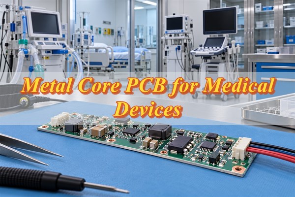
Metal core PCB for medical devices helps manage heat in surgical lighting, diagnostic equipment, and medical power electronics. Dielectric insulation, thermal resistance, and manufacturing quality remain critical to reliable operation.

EBest Circuit provides custom aluminum and copper core PCB manufacturing, SMT assembly, and free DFM reviews. Its ISO 13485 quality-management certification supports controlled manufacturing for medical-electronics projects within the certificate’s stated entity, site, and scope.

Metal Core PCB for Medical Devices, https://www.bestpcbs.com/blog/2026/10/metal-core-pcb-for-medical-devices/

Which Medical Devices Benefit from Metal Core PCBs?

Metal core PCBs suit medical devices with concentrated heat sources, high-power components, or limited cooling space. They are particularly useful when a conventional FR4 board cannot keep component temperatures within the design limit.

  • Surgical and examination lighting: Aluminum core PCBs transfer heat from high-brightness LED arrays toward the lamp housing or heatsink, helping control LED temperatures during extended operation.
  • Medical phototherapy equipment: Metal substrates spread heat from densely arranged therapeutic LEDs, supporting stable optical output and integration with the equipment’s cooling system.
  • Medical diagnostic equipment: Optical excitation sources and fluorescence detection modules may use MCPCBs to reduce temperature-related instability that can affect measurement consistency.
  • Dental curing and examination devices: Compact high-intensity LED modules benefit from efficient heat transfer where installation space limits conventional cooling options.
  • Medical power electronics: MOSFETs, DC-DC converters, and other power components may use metal substrates when conventional PCB constructions cannot dissipate sufficient heat.

Low-power monitoring, communication, and signal-processing boards may be better suited to FR4, particularly when complex multilayer routing is required.

How Do Metal Core PCBs Improve Thermal Management in Medical Equipment?

Metal core PCBs transfer heat from electronic components through a thermally conductive dielectric into an aluminum or copper substrate. The metal base then spreads heat toward a heatsink, equipment chassis, or another cooling surface.

Metal Core PCB for Medical Devices, https://www.bestpcbs.com/blog/2026/10/metal-core-pcb-for-medical-devices/

A typical single-sided MCPCB contains a copper circuit layer, an insulating dielectric, and a metal substrate. The dielectric must provide electrical isolation without creating excessive thermal resistance.

Rθ = t / (k × A)

Here, t is dielectric thickness in meters, k is thermal conductivity in W/(m·K), and A is the effective heat-transfer area in square meters.

For example, a dielectric with 100 μm thickness, 2 W/(m·K) thermal conductivity, and an assumed 100 mm² heat-transfer area has a calculated thermal resistance of 0.5 K/W. At a uniform heat flow of 20 W, the estimated temperature difference across that dielectric alone is 10°C.

The actual component temperature also depends on solder joints, component packaging, lateral heat spreading, thermal interface materials, and the cooling system. Medical equipment intended for continuous operation should be evaluated at its maximum expected load, ambient temperature, and duty cycle.

Metal Core PCB vs FR4 for Medical Devices: Which Is Better?

Metal core PCBs are better suited to concentrated heat dissipation, while FR4 offers greater flexibility for complex multilayer circuits and lower-power medical electronics.

Comparison Metal Core PCB FR4 PCB
Base structure Aluminum or copper with insulating dielectric Glass-reinforced epoxy laminate
Thermal management Metal substrate supports efficient heat spreading Relies on copper planes, thermal vias, and external cooling
Electrical insulation Requires a qualified dielectric layer Provided by laminate construction
Circuit complexity Standard IMS is commonly single-sided; complex structures require specialized processing Supports conventional multilayer routing
Mechanical properties Rigid metal substrate provides structural support Available in different thicknesses and constructions
Weight Depends on metal type and thickness Often suitable for lightweight multilayer electronics
Relative cost Usually higher for comparable simple circuits Generally lower for conventional designs
Medical applications LED modules, optical sources, and concentrated power circuits Monitoring, communication, processing, and control boards

An MCPCB becomes practical when an FR4 design cannot meet its thermal limits after considering copper spreading, thermal vias, and improvements to the cooling system.

For medical equipment combining high-power LEDs with complex control circuitry, a separate MCPCB thermal module and FR4 control board may provide a more practical construction.

Aluminum vs Copper Core PCB: Which Is Better for Medical Applications?

Aluminum core PCBs balance thermal performance, weight, and cost, while copper core PCBs offer higher substrate thermal conductivity for concentrated heat sources.

Parameter Aluminum Core PCB Copper Core PCB
Base metal conductivity Approximately 150–230 W/(m·K), depending on alloy and condition Approximately 380–400 W/(m·K), depending on grade and condition
Density Approximately 2.7 g/cm³ Approximately 8.9 g/cm³
Heat spreading Good Higher potential
Weight Lower Higher
Material cost Generally lower Generally higher
Manufacturing Common for standard IMS structures May involve higher material and processing costs
Suitable applications Surgical lighting, examination lamps, and phototherapy modules Compact optical sources and high-heat-flux power modules
Main limitation Lower thermal conductivity Greater weight and cost

For medical LED modules with adequate heatsink contact, aluminum is often a practical starting point. Copper becomes more attractive when heat is concentrated in a small area and the metal substrate limits lateral heat spreading.

If dielectric resistance or heatsink contact dominates the thermal path, replacing aluminum with copper may produce only a limited temperature reduction.

What Technical Specifications Matter for Medical Metal Core PCBs?

For a metal core PCB for medical devices, the critical specifications are dielectric thermal performance, electrical insulation, circuit copper thickness, substrate thickness, and mechanical tolerances.

Specification Typical Design Reference Selection or Acceptance Criteria
Base material Aluminum or copper Thermal load, weight, and cost
Dielectric conductivity Common grades around 1–3 W/(m·K) Approved material datasheet and thermal requirements
Dielectric thickness Often 75–150 μm Thermal resistance and insulation performance
Circuit copper Common options of 1–3 oz Current capacity, trace geometry, and heat distribution
Finished thickness Often approximately 0.8–3.0 mm Mechanical fit and mounting requirements
Surface finish ENIG, OSP, lead-free HASL, or another qualified finish Solderability and assembly compatibility
Dielectric withstand Project-specific Test method, voltage, duration, and acceptance limit
Board flatness Drawing-specific Heatsink contact and mounting alignment
Operating temperature Application-specific Component limits and material ratings

Dielectric selection requires balancing conductivity, thickness, and insulation performance. A thinner dielectric generally reduces thermal resistance, but it must still satisfy the required electrical-insulation conditions.

Electrical insulation should be specified through measurable requirements, including the approved dielectric material, test voltage, duration, and acceptance criteria. Required creepage and clearance depend on the equipment’s electrical-safety design.

Mechanical requirements should define mounting-hole positions, critical dimensions, flatness, and the heatsink interface. Thermal acceptance criteria should identify operating power, ambient temperature, measurement location, stabilization conditions, and the maximum allowable component temperature.

How Can Engineers Avoid Thermal and Insulation Failures in Medical MCPCB Design?

The main failure risks in medical MCPCB designs are localized overheating, damaged insulation, poor heatsink contact, and thermal-expansion stress. These problems may develop during extended operation even when initial electrical testing is successful.

  • Local hot spots: Review component power loss, thermal-pad dimensions, solder attachment, and heat spreading. High temperatures near a component can indicate restrictions in the local thermal path.
  • Dielectric breakdown: Check insulation thickness and electrical clearance around circuit features, metal edges, and mounting holes. Exposed metal or drilling damage may create unintended conductive paths.
  • Poor heatsink contact: Inspect mounting flatness, thermal-interface material, fastening pressure, and contact area. Air gaps can increase thermal resistance.
  • Thermal-cycling stress: Account for differences in expansion among the metal base, dielectric, solder joints, and components. Repeated temperature changes can contribute to solder fatigue or interfacial damage.
  • Temperature-sensitive components: Position sensitive analog circuitry and sensors away from significant heat sources where practical because metal substrates can spread heat into nearby regions.

When investigating overheating, compare component temperature, local metal-base temperature, and heatsink temperature to locate the dominant thermal resistance. A large difference between the metal base and heatsink may indicate poor contact, while excessive component temperature relative to the nearby metal base may point to component attachment or local heat-transfer limits.

How Are Metal Core PCBs for Medical Devices Manufactured and Assembled?

Medical metal core PCB production combines substrate preparation, circuit fabrication, metal machining, surface finishing, and SMT assembly. The process must maintain dielectric insulation, mechanical accuracy, and reliable solder joints.

PCB Manufacturing Process

  1. Select and verify materials: Start from the approved stackup and select the aluminum or copper substrate, thermally conductive dielectric, and circuit copper. Verify material identity, thickness, dielectric properties, and surface condition so an incorrect laminate does not enter imaging.
  2. Image and etch the circuit: Apply photoresist, expose and develop the circuit pattern, and etch unwanted copper. Inspect conductor dimensions and spacing against the released fabrication data before metal machining can hide or compound an imaging error.
  3. Drill and route the metal panel: Machine mounting holes, slots, and board outlines with suitable tooling. Check dimensions, metal burrs, exposed edges, and dielectric condition because machining damage can reduce clearance or create an unintended conductive path.
  4. Apply solder mask and surface finish: Process the specified solder mask and finish, such as ENIG, OSP, or lead-free HASL. Verify mask registration and pad condition so the assembly surface matches the released finish and solderability requirements.
  5. Inspect and electrically test the PCB: Verify continuity, isolation, board dimensions, and critical mounting features against the drawing. Release the bare board only when the recorded results meet the order’s acceptance criteria.

PCB Assembly Process

  1. Print and inspect solder paste: Apply paste through the approved stencil and use SPI when included in the agreed inspection plan. Evaluate deposit volume, alignment, and printing defects before component placement.
  2. Place and verify components: Mount LEDs, power devices, resistors, and other components with SMT equipment. Check orientation, placement accuracy, and thermal-pad alignment against the assembly data before reflow.
  3. Profile and run reflow: Develop a temperature profile suited to the metal substrate’s thermal mass, solder paste, and component limits. Use thermocouples at representative locations to confirm adequate joint formation without excessive component heating.
  4. Inspect the assembled board: Use AOI for placement and visible solder joints. Add X-ray inspection for hidden connections or solder-voiding criteria only when the package, thermal pad, and agreed inspection scope require it.
  5. Run agreed tests and protect shipment: Perform the specified electrical or functional tests, record the applicable result, and package completed assemblies to prevent mechanical or ESD damage in transit.

What Quality Tests and Certifications Should Medical MCPCB Manufacturers Provide?

Medical MCPCB suppliers should provide electrical-test results, insulation verification, dimensional records, and the quality-system evidence required by the order. The exact evidence depends on the PCB construction, assembly scope, and medical-equipment requirements.

Metal Core PCB for Medical Devices, https://www.bestpcbs.com/blog/2026/10/metal-core-pcb-for-medical-devices/

Quality Tests

  • Electrical testing: Verifies circuit continuity and isolation to identify open circuits, shorts, and unintended electrical connections.
  • Dielectric withstand and insulation resistance: Confirms insulation performance under specified electrical conditions. Records should include the method, voltage, duration, acceptance limits, and measured results where applicable.

  • Dimensional inspection: Checks board thickness, outline, mounting holes, and critical dimensions against the approved fabrication drawing.
  • AOI, SPI, and X-ray inspection: Detect relevant manufacturing and assembly defects. SPI assesses solder-paste deposits, AOI identifies visible defects, and X-ray supports inspection of hidden solder joints where required.
  • Thermal and functional testing: Evaluates component temperatures, hot spots, or specified circuit functions under defined operating conditions. Thermal cycling or other reliability tests may be added when required by the qualification plan.

  • Material traceability: Links the manufactured PCB to its approved substrate, dielectric material, production lot, and relevant inspection records.

Certifications and Standards

  • ISO 13485:2016: Defines quality-management-system requirements for organizations involved in medical devices and related services. Buyers should verify the certificate’s entity, site, scope, and validity.
  • ISO 9001: Provides general quality-management-system requirements. ISO 9001:2026 is the current edition; buyers should also check the supplier’s certificate version and transition status.
  • IPC-A-600: Provides acceptability criteria for bare printed boards. The applicable revision and product class should be stated in the purchasing documents.
  • IPC-A-610: Provides acceptability criteria for electronic assemblies. The applicable revision and class should match the assembly contract.
  • IEC 60601-1: Covers general requirements for basic safety and essential performance of applicable medical electrical equipment and systems; collateral or particular standards may also apply.

An ISO 13485 certificate applies to the certified quality-management system and scope, not to an individual PCB product. IEC 60601-1 requirements are assessed at the equipment level. Buyers should verify certificate validity, manufacturing-site coverage, the applicable standards and revisions, and the inspection documents included with the order.

Why Choose EBest Circuit for Medical Metal Core PCB Manufacturing?

EBest Circuit combines custom metal core PCB fabrication, component sourcing, SMT assembly, and engineering support for medical-electronics manufacturers. Each capability should be confirmed against the released stackup, files, inspection scope, and certificate requirements for the project.

  • ISO 13485 and ISO 9001 certification: Supports controlled manufacturing, documentation, and production traceability within the applicable certificate entity, site, scope, and validity period.
  • Free DFM review: Engineers can check dielectric specifications, copper features, mounting-hole insulation, mechanical dimensions, and assembly files to identify manufacturability issues before fabrication.
  • Aluminum and copper core options: Published capability references cover single-sided, double-sided, and selected multilayer constructions, plus dielectric grades of 0.8, 1.0, 1.5, 2.0, and 3.0 W/(m·K). Final material and construction suitability are confirmed for each project.
  • Integrated PCB and PCBA workflow: Fabrication, component sourcing, SMT assembly, and agreed inspection can be coordinated under one project to reduce supplier handoffs.
  • Prototype-to-volume support: Approved stackups, materials, BOMs, and inspection requirements can be controlled across repeat orders to support manufacturing consistency.
  • Defined testing and documentation: Electrical testing, SPI, AOI, applicable X-ray inspection, and customer-defined functional or thermal testing are quoted only within the confirmed production scope.
  • International delivery support: Customized PCB and PCBA manufacturing is coordinated from China-based operations for overseas medical-electronics customers.

Medical Metal Core PCB Application Case: Improving Thermal Stability in a Diagnostic Device

An EBest customer project used a copper-base PCB to improve the thermal stability of a compact optical-detection module without increasing its enclosure size. The project result was evaluated at prototype level before moving into small-batch production.

Project Background

A medical diagnostic equipment manufacturer experienced unstable optical readings in a compact laboratory detection module. The original FR4 PCB passed initial functional testing, but prolonged operation caused heat to accumulate around the LED excitation source, resulting in brightness drift and inconsistent signal output.

Customer Requirements and Challenges

The customer needed better thermal stability without increasing the module size. The replacement PCB also had to maintain electrical insulation, reliable LED soldering, and accurate mechanical fit with the existing enclosure. The main challenge was reducing heat buildup while preserving the optical and assembly requirements.

EBest Circuit’s Solution

EBest reviewed the LED thermal pads, copper distribution, dielectric material, substrate thickness, and enclosure contact points. The engineering team replaced the FR4 construction with a copper-base PCB, enlarged the thermal-pad area, selected a higher-conductivity dielectric, and improved the heat-transfer interface with the metal enclosure. Thermal imaging was included in prototype evaluation to assess heat distribution during operation.

Project Results

The revised prototype reduced localized hot spots and improved LED output stability during continuous operation. The customer obtained a more stable optical module without increasing its dimensions. Following prototype verification, the project advanced to small-batch production with defined material specifications and inspection requirements for subsequent orders.

FAQs About Metal Core PCBs for Medical Devices

Q1. Can a metal core PCB use plated through-holes?

A1. Yes, certain MCPCB constructions support plated through-holes, but they require suitable insulation and specialized processing. Manufacturability depends on the stackup, metal thickness, and electrical-isolation requirements.

Q2. Is the aluminum or copper substrate connected to ground?

A2. Not automatically. The metal base may be electrically isolated or intentionally connected through a designed grounding structure. Grounding and isolation must be defined in the equipment design, especially around mounting screws and exposed metal.

Q3. Can medical MCPCBs support double-sided component assembly?

A3. Some double-sided and multilayer MCPCB constructions support components on both surfaces. The required interconnections, insulation, and assembly processes are more complex, so the complete stackup must be reviewed before manufacturing.

Q4. Are metal core PCBs suitable for portable medical equipment?

A4. Yes, especially when a compact power or LED module generates concentrated heat. Aluminum may provide a suitable balance of thermal performance and weight, depending on board thickness and mechanical requirements.

Q5. Can medical MCPCBs withstand sterilization?

A5. Compatibility depends on the sterilization process and the complete assembly. Steam, moisture, chemicals, and repeated heating can affect dielectric materials, solder joints, and components. The assembly must be qualified for the intended sterilization method.

Q6. Can damaged components be reworked on a metal core PCB?

A6. Rework may be possible, but the metal base changes heat distribution around the repair area. A qualified rework profile and temperature monitoring help reduce the risk of component or dielectric damage.

Q7. Are MCPCBs suitable for disposable medical equipment?

A7. They may be appropriate for disposable products containing significant heat sources. Power density, operating duration, weight, and cost should determine whether a metal substrate is justified.

Q8. Can an MCPCB eliminate the need for a separate heatsink?

A8. Sometimes, but not automatically. The metal substrate spreads heat, while the surrounding structure must release it to the environment. Heatsink removal requires thermal verification under the intended operating conditions.
Q9. What affects the lead time for custom medical metal core PCBs?

A9. Lead time depends on substrate availability, dielectric requirements, circuit complexity, machining, quantity, assembly, and testing. A production schedule should be confirmed after engineering and material review.

How Can You Get a Medical Metal Core PCB Quote?

A useful medical MCPCB quotation starts with released fabrication data, thermal and insulation requirements, assembly files, and the required inspection records. EBest Circuit can review the following inputs for a manufacturing and assembly quotation:

  • PCB files: Gerber or ODB++ data, drill files, mechanical drawings, and stackup.
  • Material specifications: Aluminum or copper substrate, dielectric requirements, copper thickness, board thickness, and surface finish.
  • Thermal and electrical requirements: Power dissipation, operating temperature, insulation specifications, and acceptance criteria.
  • Assembly information: BOM, pick-and-place files, assembly drawings, and required functional tests.
  • Quality requirements: Applicable IPC acceptance class, inspection requirements, and traceability documents.
  • Order details: Prototype or production quantity, target delivery date, and delivery location.

The returned engineering review can identify manufacturing-feasibility questions and the material, insulation, assembly, test, or documentation choices that affect the quotation and production schedule.

For a free DFM review and custom medical metal core PCB quotation, send the released files and requirements to sales@bestpcbs.com.

You may also like

Aluminum-Core PCB Manufacturers, Customization & Low Volume
Tuesday, July 8th, 2025

Why choose aluminum-core PCB for thermal management? This guide explores aluminum PCB materials, advantages, applications, and manufacturing solutions.

  • Does your electronic product suffer from performance degradation or shortened life due to insufficient heat dissipation?
  • Is it difficult to choose between the high cost of copper substrates and the heat dissipation requirements?
  • Does small batch customization face the problem of long delivery time and high minimum order quantity?

EBest Circuit (Best Technology) can Provide:

  • We provide high thermal conductivity aluminum substrates, which improve heat dissipation efficiency by 60% to ensure stable operation of the equipment.
  • Our aluminum substrate solution saves 30% of the cost compared to copper substrates, while meeting strict heat dissipation requirements.
  • Support 1 piece minimum order, 72 hours fast proofing, and flexible production throughout the entire process.

Welcome to contact us if you have any request for aluminum core PCB: sales@bestpcbs.com.

What Does Aluminum-Core PCB Mean?

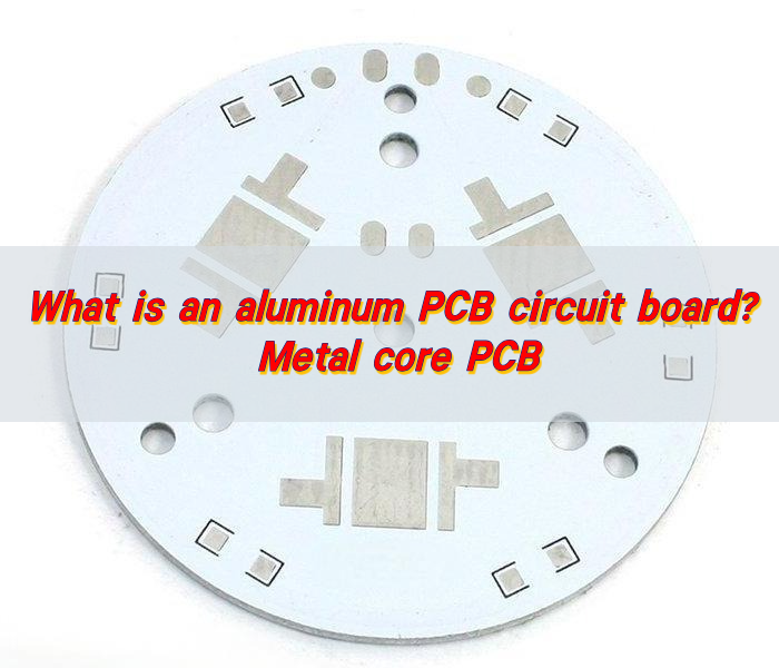
An aluminum-core PCB, also known as Metal Core PCB (MCPCB) or Insulated Metal Substrate PCB (IMS PCB), is a specialized circuit board that uses an aluminum base layer instead of traditional FR4 material. The aluminum core serves as both a structural support and thermal conductor, efficiently dissipating heat from components like LEDs or power electronics.

These boards typically consist of three layers: a copper circuit layer, a thermally conductive dielectric layer, and the aluminum substrate. Unlike conventional PCBs, Aluminum-Core PCBs excel in high-power applications where heat management determines performance and longevity. The IMS PCB variant emphasizes the insulated dielectric layer’s role in preventing electrical shorts while maintaining optimal thermal transfer.

What Does Aluminum-Core PCB Mean?

What Is Aluminum Core PCB Material?

Copper Circuit Layer‌

  • Forms the conductive pathways for electrical signals
  • Typically 1-8 oz (35-280μm) copper foil

Dielectric Layer‌

  • Electrically insulating but thermally conductive
  • Contains ceramic-filled epoxy (1-3 W/m·K thermal conductivity)
  • Withstands ≥3000V electrical isolation

Aluminum Base‌

  • 5052 or 6063 alloy (100-220 W/m·K thermal conductivity)
  • 1.0-3.2mm thickness for heat spreading and mechanical support

What Are the Advantages of Aluminum-Core PCB?

  • Enhanced Thermal Conductivity – Aluminum dissipates heat faster than traditional FR4 or ceramic substrates, reducing thermal stress on components and improving long-term reliability.
  • Mechanical Durability – Resists bending, vibration, and physical stress, making it suitable for automotive, industrial, and high-vibration environments.
  • Lightweight Construction – Offers a balance of strength and reduced weight compared to copper-core alternatives, aiding portability in consumer electronics.
  • Cost Efficiency – Lower material and manufacturing costs than copper-based PCBs, ideal for cost-sensitive mass production projects.
  • Dimensional Stability – Minimal expansion/contraction under temperature fluctuations ensures consistent solder joint integrity and component alignment.
  • Simplified Cooling Systems – Reduces reliance on external heatsinks or fans by leveraging direct metal-to-component heat transfer.
What Are the Advantages of Aluminum-Core PCB?

What Are Types of Aluminum-Core PCB?

Single-Layer Aluminum PCB:

  • Single-sided circuit with aluminum core as the base layer, ideal for basic thermal management in LED lighting or power modules.

Double-Layer Aluminum PCB

  • Dual-sided circuitry with aluminum substrate between layers, enabling compact designs for motor controls or automotive electronics.

Multi-Layer Aluminum PCB

  • Stacked layers with aluminum core integrated into internal positions, balancing circuit density and thermal performance in high-power applications.
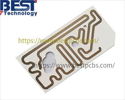
When to Use Aluminum PCB?

Application of aluminum-core PCB:

  • High-Power LED Lighting – Manages heat in streetlights/headlights to prevent LED degradation.
  • Automotive Power Systems – Handles vibration/heat in engine controls or battery modules.
  • Compact Power Modules – Enables dense DC/DC converters without external cooling.
  • Industrial Motor Controls – Stabilizes high-current transistors in factory drives.
  • Outdoor Electronics – Resists moisture/UV in solar inverters or weather sensors.
  • Cost-Sensitive Thermal Needs – Balances budget/performance in consumer chargers/adapters.
  • Medical Instrumentation – Maintains temperature precision in diagnostic/imaging tools.
When to Use Aluminum PCB?

Differences Between Copper Core vs Aluminum Core PCB

Here are the 8 most important differences between Copper Core and Aluminum Core PCBs:

Thermal Conductivity‌

  • Copper Core: ~400 W/m·K (superior heat transfer)
  • Aluminum Core: 100-220 W/m·K (effective but less conductive)

Weight‌

  • Copper Core: Heavy (~8.96 g/cm³)
  • Aluminum Core: Light (~2.7 g/cm³), better for portable devices

Cost‌

  • Copper Core: More expensive (~3-5x aluminum)
  • Aluminum Core: More cost-effective

Thermal Expansion‌

  • Copper Core: Matches well with copper traces
  • Aluminum Core: Higher CTE mismatch requires careful design

Applications‌

  • Copper Core: Extreme high-power electronics, aerospace
  • Aluminum Core: LED lighting, automotive, consumer electronics

Corrosion Resistance‌

  • Copper Core: Requires protective coatings
  • Aluminum Core: Naturally forms protective oxide layer

EMI Shielding‌

  • Copper Core: Better electromagnetic interference protection
  • Aluminum Core: Adequate for most commercial uses

Manufacturing Process‌

  • Copper Core: Requires specialized etching/plating
  • Aluminum Core: Easier to machine and process
Differences Between Copper Core vs Aluminum Core PCB

How to Optimize Your Thermal Design to Achieve Efficient Heat Dissipation?

  • Select High-Thermal-Conductivity Substrates – Prioritize aluminum (200-250 W/m·K) or copper (380-400 W/m·K) cores over FR4 to directly channel heat away from components.
  • Position High-Power Components Near the Metal Base – Place MOSFETs, LEDs, or power transistors in direct proximity to the substrate to minimize thermal resistance paths.
  • Expand Surface Area for Radiative Cooling – Integrate fins, exposed metal pads, or extended substrate sections to enhance heat dissipation through air contact.
  • Apply Thermal Interface Materials (TIMs) – Use silicone pads, greases, or phase-change films to eliminate air gaps between components and the substrate, reducing thermal resistance by 30-50%.
  • Design Airflow Channels or Active Cooling – Create ventilation paths or install low-profile fans to direct airflow over hot zones, critical for enclosed systems or high-ambient-temperature environments.
  • Validate with Thermal Imaging and Simulation – Test prototypes using infrared cameras under operational loads and refine designs based on hotspot analysis.

Why Choose EBest Circuit (Best Technology) As Your Aluminum-Core PCB Manufacturer?

Reasons why choose EBest Circuit (Best Technology) as your aluminum-core PCB manufacturer:

  • Fastest Turnaround – 24-hour rapid prototyping & 15-day bulk production to accelerate your time-to-market.
  • Cost Transparency – No hidden fees; competitive pricing with direct factory savings.
  • Turnkey Solution – End-to-end service (design → assembly → testing) to simplify your supply chain.
  • Free DFM Analysis – Prevent costly errors early with expert design optimization.
  • Certified & Compliant Standards – ISO 9001, ISO 13485, IATF 16949, AS9100D Certified, and UL, REACH, RoHS Compliant.
  • Thermal Management Excellence – Our 2.0mm aluminum core reduces operating temps by 25-30°C, solving overheating in LED/high-power applications.

  • Rapid Prototyping – 24-hour turnaround for double-sided MCPCB samples.
  • Cost-Efficient Scaling – 15% lower batch pricing for 500+ units without sacrificing quality.

Instant Quote

Aluminum-core PCBs deliver excellent heat dissipation for LED, automotive and power electronics applications. Their aluminum base provides superior thermal performance at lower costs than copper, available in single/double/multilayer configurations. Main selection factors include thermal conductivity requirements and dielectric properties. EBest Circuit (Best Technology) offers customized aluminum PCB solutions from prototypes to mass production with competitive pricing and fast delivery. Contact us for project-specific quotations: sales@bestpcbs.com.
You may also like

Xiaomi Integrated IKEA’s Smart Lighting Products in IoT Platform
Friday, December 7th, 2018

Xiaomi co-founder and CEO Lei Jun said,“To connect everything needs collaboration with others.”On November, 2018, Xiaomi announced a strategic partnership with IKEA. IKEA’s full range of smart lighting products will be connected to Xiaomi’s IoT platform starting this December in China. This marks the first time IKEA has partnered with a Chinese technology company.

Through the cooperation, the lighting products of IKEA can be controlled by smart speakers including Xiaomi’s AI voice assistant Xiao Ai, which is currently only available for Chinese Mandarin speakers.

Most of Xiaomi’s fans might know that its ‘Mi Home’ app designed to manage Xiaomi devices and products as well as Xiao Ai will be compatible in IKEA’s smart lighting products.

Speaking at the Xiaomi AIOT Developers Conference, Lei Jun said the combination of artificial intelligence (AI) and IoT will be the core strategy of his company’s business in ten years.

Fan Dian, General Manager of the IoT platform department of Xiaomi, said, “IKEA and Xiaomi share very similar values and I believe our collaboration will accelerate the development of the smart home industry across the world.”

According to the company’s third-quarter financial report, Xiaomi has connected 132 million IoT devices in the ended September.

With a goal to allow people to fully embrace AI in daily life at home, more and more PCBs are applied into connected home. Because the benefits of high thermal conductivity and heat dissipation highly meet the requirements of the market, the aluminum core PCB and ceramic PCB are the perfect match for LED lights. If you would like to add more colors for your smart home, the aluminum core PCB and ceramic PCB from EBest Circuit (Best Technology) are nice choice.

You may also like