PCB manufacturing PCB manufacturing
Home > Blog

copper core pcb

Heat Transfer Coefficient of Copper: H Value Guide
Friday, June 26th, 2026

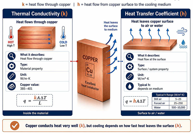
Heat transfer coefficient of copper is an important concept in thermal management, especially for heat sinks, copper core PCBs, heavy copper PCBs, copper inlay boards, PCB bus bars, heat pipes, cold plates, vapor chambers, and power electronics assemblies. Many people search for this term expecting one fixed value, just like the thermal conductivity of copper. In reality, these two terms are different. Copper has a high thermal conductivity, usually around 385–401 W/m·K for pure copper at room temperature, which describes how well heat travels through copper itself.

The heat transfer coefficient, often represented by h, describes how efficiently heat moves from a copper surface to a surrounding medium, such as air, water, oil, steam, or another contact surface. It is usually measured in W/m²·K and depends on cooling medium, airflow or liquid flow, surface area, surface finish, temperature difference, contact quality, and the full thermal path. For PCB, PCBA, heat sink, LED module assembly, EV charger, AI server power board, and industrial power electronics design, this distinction is important: copper can spread heat very well, but the heat still needs a real exit path.
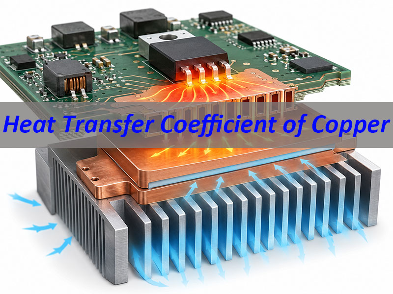
Heat Transfer Coefficient of Copper

What Is the Heat Transfer Coefficient of Copper?

The heat transfer coefficient of copper describes the rate at which heat moves between a copper surface and its surrounding environment. In heat transfer calculations, it is usually written as h.

The basic heat transfer equation is:

Q = h × A × ΔT

Where:

SymbolMeaning
QHeat transfer rate
hHeat transfer coefficient
AHeat transfer surface area
ΔTTemperature difference between the copper surface and the surrounding medium

This formula shows that heat transfer is not controlled by copper alone. Even if copper conducts heat quickly inside the material, the heat must still leave the copper surface.

For example, imagine the same copper plate used in three different conditions:

Copper ConditionHeat Transfer Result
Copper plate in still airHeat leaves slowly
Copper plate with fan airflowHeat leaves faster
Copper plate cooled by flowing waterHeat leaves much faster

The copper material is the same in all three cases. What changes is the cooling environment. That is why the heat transfer coefficient must always be discussed together with the actual working condition.

In simple terms:

Copper helps heat spread. The surrounding medium decides how fast heat leaves.

Is the Heat Transfer Coefficient of Copper a Fixed Value?

No. The heat transfer coefficient of copper is not a fixed material value. This is the key point to understand before using it in thermal design. Copper thermal conductivity is a material property, while the heat transfer coefficient is a surface and system property.

Pure copper has high thermal conductivity because free electrons can carry thermal energy efficiently through its metallic structure. That is why copper is widely used in heat spreaders, heat pipes, cold plates, copper base PCBs, and high-current conductive parts. However, the h value depends on how heat leaves the copper surface, not only on the copper itself.

Copper ConditionHeat Transfer Result
Still airLow
Forced airflowHigher
Flowing waterMuch higher
Copper tubeFlow-dependent
Poor contactLimited
Good contactImproved

For example, a copper heat sink in still air may have limited cooling performance because air removes heat slowly. With stronger airflow, heat removal improves because moving air reduces the warm boundary layer near the copper surface. A copper cold plate with flowing water can transfer heat much more effectively than air cooling. A copper tube in a heat exchanger also depends on flow speed, tube diameter, wall thickness, and fouling.

So the better engineering question is not simply “What is the heat transfer coefficient of copper?” A more accurate question is: What is the heat transfer coefficient of this copper surface under this cooling condition?

This small change makes the answer more practical. It helps engineers evaluate copper parts based on real working conditions instead of treating copper as if it has one universal h value.

What Is the Unit of Heat Transfer Coefficient of Copper?

The standard unit of heat transfer coefficient is:

W/m²·K

It can also be written as:

W/(m²·K)

This means watts of heat transferred per square meter of surface area for every one kelvin of temperature difference.

This unit is different from the unit used for copper thermal conductivity.

ParameterSymbolUnitWhat It Describes
Thermal conductivity of copperkW/m·KHeat conduction through copper
Heat transfer coefficienthW/m²·KHeat exchange from surface to fluid
Overall heat transfer coefficientUW/m²·KTotal heat transfer through a full system

This distinction is useful because many users confuse these values.

For example, copper thermal conductivity may be around 401 W/m·K, but that does not mean the heat transfer coefficient of copper is 401 W/m²·K. The first value describes conduction through copper. The second type of value describes convection or surface heat exchange.

In PCB thermal design, both values matter. Copper thermal conductivity helps heat move through copper traces, planes, coins, or cores. The heat transfer coefficient affects how heat leaves the board through air, a heat sink, a housing, or a liquid cooling structure.

What Is the Difference Between Heat Transfer Coefficient and Thermal Conductivity of Copper?

Thermal conductivity and heat transfer coefficient are closely related, but they describe different stages of heat movement.

Thermal conductivity of copper answers this question:

How well does heat move through copper?

Heat transfer coefficient of copper answers this question:

How well does heat move from the copper surface to air, water, or another surrounding medium?

A practical example is a copper heat sink. The copper base spreads heat quickly from a hot component. This reduces local hot spots. But the heat still needs to move from the copper surface into the surrounding air. If airflow is weak, the copper heat sink may still run hot.

Another example is a copper core PCB. The copper core can spread heat from LEDs, MOSFETs, power ICs, or charging modules. But if the board does not have good contact with a housing or heat sink, the heat may remain inside the assembly.

So thermal design has two parts:

Heat Transfer StageMain Design Focus
Heat spreading inside copperCopper thickness, copper area, copper purity, copper path
Heat removal from copper surfaceAirflow, water flow, surface area, heat sink, housing contact

This is why high copper thermal conductivity alone does not guarantee low operating temperature. A good design must include a complete thermal path.

For PCBs, this means engineers should review copper thickness, copper plane area, via structure, dielectric thermal conductivity, component placement, soldering quality, surface finish, housing contact, and airflow path together.
Heat Transfer Coefficient of Copper

What Are Typical Heat Transfer Coefficient Values for Copper in Air and Water?

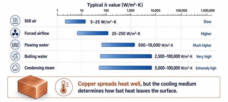
Copper does not have one fixed h value, but engineers often use typical ranges based on the cooling condition. These values are general reference ranges. Actual values should be verified by thermal simulation, testing, or project-specific calculation.

Cooling ConditionTypical Heat Transfer Coefficient Range
Natural convection in air5–25 W/m²·K
Forced convection in air25–250 W/m²·K
Water cooling500–10,000 W/m²·K
Boiling water or phase-change cooling2,500–100,000 W/m²·K
Condensing steam5,000–100,000 W/m²·K

These ranges explain why cooling method matters so much.

A copper plate in still air may not remove heat quickly, even though copper itself has excellent thermal conductivity. If a fan is added, the warm boundary layer near the copper surface becomes thinner, and heat leaves faster. If water is used as the cooling medium, heat removal can increase dramatically.

This is why high-power systems often use copper cold plates, copper tubes, heat pipes, or vapor chambers.

For PCB applications, air cooling may be enough for moderate power designs. For high-power LED modules, EV chargers, laser drivers, AI server power boards, or inverter modules, the design may require metal base PCBs, copper inlay, heavy copper, heat sinks, or liquid cooling assistance.

The key point is simple:

The copper part spreads heat. The cooling method removes heat. Both must work together.
Heat Transfer Coefficient of Copper

What Factors Affect the Heat Transfer Coefficient of Copper?

Several factors influence the heat transfer coefficient of copper in real applications. Understanding these factors helps engineers avoid thermal design mistakes.

Cooling Medium

  • Air, water, oil, and steam have different heat transfer behavior.
  • Air cooling is simple, clean, and low-cost, but its heat transfer coefficient is usually lower. Water cooling provides much stronger heat removal and is often used in high-power electronics, server cooling, EV charging, laser systems, and industrial power modules.
  • Oil cooling may be used in transformers or special power systems because it can offer insulation and stable thermal behavior. Steam condensation and boiling systems can provide very high heat transfer, but they require more complex design control.

Flow Speed

  • Flow speed has a major effect on h value. Still air creates a thick thermal boundary layer around the copper surface, which limits heat removal. Moving air reduces this layer and improves cooling.
  • The same logic applies to liquid cooling. Faster water flow usually improves heat transfer, but it also increases pressure drop and pump requirements. A practical design must balance thermal performance, noise, pressure loss, reliability, and cost.

Surface Area

  • A larger surface area allows more heat to leave. This is why heat sinks use fins. It is also why copper tubes, copper coils, and cold plates are shaped to increase contact area with air or liquid.
  • In PCB design, copper planes, thermal vias, exposed copper pads, copper coins, copper inlays, and metal bases can increase the useful heat spreading area.
  • However, more copper area only helps when the heat has a real exit path. A large copper plane inside a sealed product may spread heat, but the product can still overheat if the enclosure cannot release that heat.

Surface Condition

  • Copper surface condition also matters. Oxidation, roughness, plating, solder mask, contamination, and coating can change practical heat transfer.
  • For example, exposed copper may exchange heat differently from copper covered by solder mask. Nickel, tin, silver, ENIG, OSP, or other finishes may also influence surface contact, oxidation resistance, and assembly behavior.
  • In PCB production, surface finish is not chosen only for thermal reasons. It also affects solderability, shelf life, wire bonding, contact reliability, and cost.

Contact Resistance

  • When copper touches another material, the contact interface can become a thermal bottleneck. Air gaps, uneven pressure, poor soldering, weak thermal interface material, and rough surfaces can all increase contact resistance.
  • This is common in PCBA thermal issues. The copper may be thick enough, but the heat still cannot pass efficiently into the heat sink or metal housing.

Geometry

  • Copper geometry affects heat transfer. A copper plate, pipe, tube, rod, wire, coil, heat pipe, and copper coin all behave differently.
  • For example, the heat transfer coefficient of a copper tube depends on tube diameter, wall thickness, fluid velocity, internal surface condition, external cooling medium, and temperature difference. It cannot be judged only by the copper material.
  • In PCB design, geometry also matters. A short and wide copper path usually performs better than a long and narrow heat path. Thermal vias placed close to the heat source are usually more effective than vias placed far away.

How Does Copper Compare With Aluminum, Stainless Steel, and Other Metals?

Copper is one of the most practical metals for thermal design. Silver has higher thermal conductivity, but copper is more widely used because it offers a better balance of performance, cost, availability, machinability, and electrical conductivity.

MaterialApproximate Thermal ConductivityThermal Design Comment
Silver~429 W/m·KExcellent conductivity, but expensive
Copper~385–401 W/m·KStrong heat spreading and electrical conduction
Aluminum~205–237 W/m·KLightweight and cost-effective
Brass~80–120 W/m·KBetter mechanical/corrosion properties than pure copper, lower heat transfer
Stainless steel~14–16 W/m·KStrong and corrosion-resistant, but poor thermal conductor

Copper usually performs better than aluminum when fast heat spreading is required. This is useful when heat is concentrated in a small area, such as under a power IC, MOSFET, IGBT, LED chip, or laser diode.

Aluminum has lower thermal conductivity than copper, but it is lighter and more cost-effective. That is why aluminum heat sinks and aluminum PCBs are widely used in LED lighting, consumer electronics, automotive modules, and industrial control products.

Stainless steel is not usually selected for heat spreading. It is used when strength, corrosion resistance, or mechanical stability is more important than heat transfer.

The best material depends on the application:

Application NeedBetter Material Choice
Highest practical heat spreadingCopper
Lightweight heat sinkAluminum
High current and heat spreading togetherCopper
Low-cost LED thermal substrateAluminum PCB
Electrical insulation plus high thermal pathCeramic PCB
Corrosion-resistant structureStainless steel
Compact high-power moduleCopper core PCB or copper inlay PCB

For many real products, the best solution is not a single material. A thermal design may combine copper for heat spreading, aluminum for large fin area, ceramic for insulation, and thermal interface material for contact improvement.

What Is the Overall Heat Transfer Coefficient of Copper?

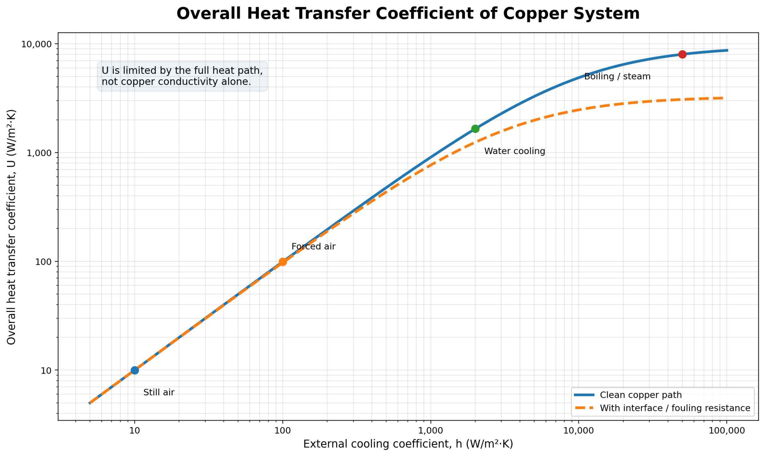
The overall heat transfer coefficient, usually written as U, describes total heat transfer through a complete system. It includes all thermal resistance in the heat path.

This is different from the convective heat transfer coefficient h, which usually describes heat exchange at one surface.

For example, a copper tube heat exchanger may include:

  • Heat transfer from hot fluid to the inner copper wall
  • Heat conduction through the copper tube wall
  • Heat transfer from the outer copper surface to air or water
  • Fouling, oxidation, or coating resistance
  • Contact resistance at joints or interfaces

The U-value combines these effects. This makes it useful for heat exchangers, cold plates, copper tubes, liquid cooling systems, and multilayer thermal structures.

The same concept applies to PCB thermal design.

A copper core PCB thermal path may include:

Thermal Path SegmentPossible Thermal Issue
Component junction to packagePackage thermal resistance
Package to solder jointSolder voids or poor wetting
Solder joint to copper padPad size and copper connection
Copper pad to copper plane/coreCopper thickness and layout
Copper layer to dielectricDielectric thermal conductivity
Board to heat sink or housingContact resistance and flatness
Housing to airAirflow and surface area

This is why real thermal performance cannot be judged by copper alone. Copper is important, but the complete heat path decides the final temperature.
Heat Transfer Coefficient of Copper

Why Does the Heat Transfer Coefficient of Copper Matter in PCB, PCBA, and Heat Sink Design?

Copper is central to PCB manufacturing because it supports both electrical conduction and heat spreading. In high-power products, copper is not only a circuit material. It becomes part of the thermal management structure.

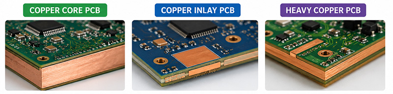
Heavy Copper PCB

  • Heavy copper PCB uses thicker copper to carry higher current and reduce resistance-related heating. It is often used in power supplies, EV chargers, battery systems, industrial controllers, motor drives, and automotive electronics.
  • Heavy copper also helps spread heat from power components. However, thicker copper does not automatically solve every thermal problem. Designers must also check trace width, copper balance, etching tolerance, soldering quality, thermal relief design, and the final heat exit path.
  • A common mistake is adding thick copper without improving airflow, heat sink contact, or board-to-housing conduction. In that case, heat spreads across the board but may not leave the product efficiently.

Copper Core PCB

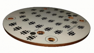
Copper core PCB uses a copper base or copper core to move heat away from components. Compared with standard FR4, copper core structures offer much stronger heat spreading.

Copper core PCB is useful for:

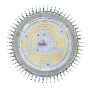
  • High-power LED modules
  • Automotive lighting
  • MOSFET and IGBT boards
  • EV charging systems
  • Industrial power modules
  • Compact power conversion boards

The copper core spreads heat quickly, while the final temperature depends on dielectric thermal conductivity, copper thickness, contact area, heat sink design, and airflow.

Copper Inlay and Copper Coin PCB

  • Copper inlay and copper coin PCB structures place copper directly under high-heat components. This creates a shorter thermal path from the component to the heat dissipation structure.
  • These designs are useful when heat is concentrated in a small area, such as under power ICs, RF devices, LEDs, high-current terminals, or power modules.
  • For manufacturing, copper inlay and copper coin designs need careful DFM review. The supplier should check cavity tolerance, bonding reliability, copper thickness, lamination control, solderability, and board flatness.

Thermal Vias and Copper Planes

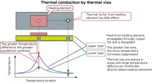
Thermal vias transfer heat from one PCB layer to another. Copper planes spread heat across a wider area. Together, they help reduce hot spots.

For better performance:

  • Place thermal vias close to the heat source
  • Use enough via quantity and copper plating thickness
  • Connect vias to large copper planes
  • Avoid isolated copper areas with no heat exit path
  • Consider solder wicking risk under components
  • Check whether vias should be filled, capped, or tented

Thermal vias are useful, but they are not magic. If the bottom side has no heat sink, no airflow, or no metal housing contact, the improvement may be limited.

Heat Sink and Housing Contact

  • A copper PCB or copper heat spreader needs a good contact path to the heat sink or enclosure. Poor contact pressure, uneven surfaces, air gaps, or weak thermal pads can reduce heat transfer.
  • For high-power PCBA, mechanical assembly matters as much as PCB material. Screw positions, flatness, thermal grease, gap pad compression, and enclosure material should be reviewed during design.

Common Design Mistakes

Many thermal problems are caused by layout and structure decisions made before production. Common mistakes include:

MistakeWhy It Causes Problems
Treating copper thermal conductivity as h valueLeads to wrong thermal assumptions
Adding copper without a heat exit pathHeat spreads but remains inside the product
Ignoring dielectric thermal resistanceMetal base performance becomes limited
Using too few thermal viasHeat cannot move efficiently between layers
Placing thermal vias too far from the heat sourceThermal path becomes longer
Covering key copper areas with solder maskSurface heat transfer and contact may be reduced
Poor heat sink contactContact resistance becomes the bottleneck
Ignoring solder voids under power partsJunction temperature may rise
Choosing heavy copper without DFM reviewEtching, spacing, soldering, and warpage risks increase

What Should Buyers Check Before Ordering Copper-Based Thermal PCBs?

For buyers and engineers, the right questions before ordering are important. A reliable PCB manufacturer should review not only board dimensions and copper thickness, but also the real thermal and electrical requirements.

Before ordering, check:

Item to CheckWhy It Matters
Copper thicknessAffects current capacity and heat spreading
Copper distributionAffects warpage, etching, and thermal balance
Base materialFR4, aluminum, copper, or ceramic changes the thermal path
Dielectric thermal conductivityCritical in metal core PCB
Thermal via designAffects heat transfer between layers
Surface finishAffects solderability, oxidation, and contact reliability
Solder mask openingAffects exposed copper and heat sink contact
Heat sink contact areaDetermines practical heat removal
Operating currentAffects Joule heating and trace temperature rise
Component power lossDetermines hot spot risk
Assembly methodAffects solder voids, contact, and reliability
Product environmentAirflow, enclosure, temperature, and humidity matter

This is where PCB manufacturing experience becomes important. A design may look correct in a schematic, but production details can affect thermal performance. DFM review helps identify these risks before fabrication and assembly.

At Best Technology, thermal PCB projects are usually reviewed from several angles: copper structure, material selection, stack-up, thermal path, manufacturability, assembly reliability, and application environment.
Heat Transfer Coefficient of Copper

FAQs About Heat Transfer Coefficient of Copper

Q1: What is the heat transfer coefficient of copper in W/m²·K?
There is no single universal value. Typical values may range from low natural air convection to very high liquid cooling or phase-change cooling values, depending on actual working conditions.

Q2: What is the heat transfer coefficient of copper to air?
Copper-to-air heat transfer is usually limited in still air. Forced airflow improves heat removal by reducing the warm boundary layer near the copper surface.

Q3: What is the heat transfer coefficient of copper and water?
Copper-to-water heat transfer is usually much stronger than copper-to-air heat transfer. This is why copper tubes, cold plates, and liquid cooling blocks are used in high-power systems.

Q4: Is copper better than aluminum for heat transfer?
Copper has higher thermal conductivity than aluminum, so it spreads heat faster. Aluminum is lighter and more cost-effective, so it is still widely used for heat sinks and LED aluminum PCBs.

Q5: Is copper better than stainless steel for thermal management?
Yes, when heat spreading is the main goal. Copper conducts heat much better than stainless steel. Stainless steel is usually chosen for strength, corrosion resistance, or structure.

Q6: What is the overall heat transfer coefficient of copper?
The overall heat transfer coefficient, or U-value, describes heat transfer through a complete system. It includes convection, conduction, surface condition, contact resistance, and other thermal barriers.

Q7: Why does the heat transfer coefficient of copper matter in PCB design?
It matters because copper spreads heat inside the PCB, but heat must still leave the board through air, heat sinks, metal housings, or liquid cooling. Good thermal PCB design must consider the complete heat path.

Q8: Can thicker copper always improve PCB heat dissipation?
Thicker copper can improve heat spreading and current capacity, but it does not always reduce final temperature. The board also needs a proper heat exit path, such as airflow, a heat sink, a metal base, or housing contact.

Q9: What PCB types are suitable for high thermal performance?
Common options include heavy copper PCB, copper core PCB, aluminum PCB, ceramic PCB, copper inlay PCB, and copper coin PCB. The best choice depends on power density, insulation requirement, current load, cost, and assembly structure.

To sum up, the heat transfer coefficient of copper is important in thermal design, but it should not be treated as a fixed copper material property. Copper has excellent thermal conductivity, which allows it to spread heat quickly. The heat transfer coefficient describes how efficiently heat leaves or enters the copper surface under specific cooling conditions.

For PCB and PCBA applications, copper plays a key role in heat spreading, current carrying, and product reliability. Heavy copper PCB, copper core PCB, copper inlay PCB, copper coin PCB, thermal vias, and copper planes can all improve thermal performance when they are designed with a complete heat path.

The best thermal design is not just about using more copper. It is about selecting the right copper structure, material stack-up, dielectric layer, surface finish, heat sink contact, airflow path, and assembly process.

At EBest Circuit (Best Technology), we support thermal management PCB and PCBA solutions, including copper core PCB, heavy copper PCB, aluminum PCB, ceramic PCB, copper inlay PCB, copper coin PCB, and full and partial turnkey PCB assembly. If your project involves LED modules, EV chargers, AI server power boards, industrial control boards, automotive PCBA, or high-current electronics, you can send your Gerber files, BOM, stack-up, copper thickness, and heat dissipation requirements to sales@bestpcbs.com for an engineering review and quotation.
You may also like

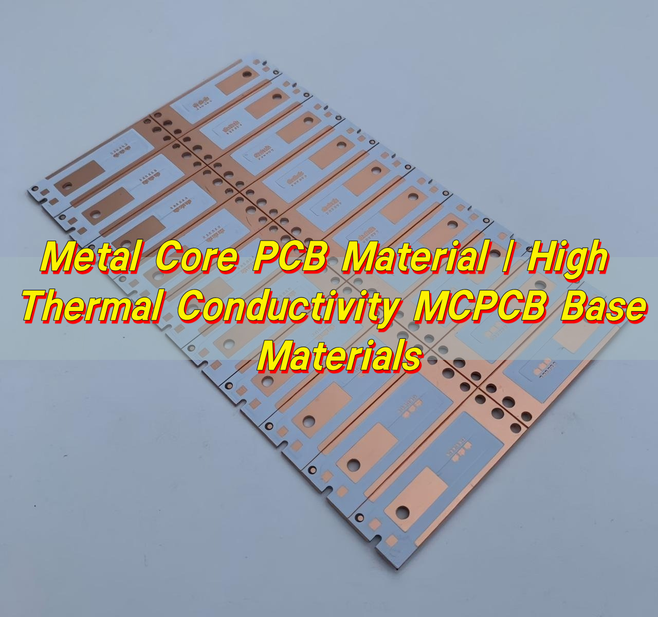
Metal Core PCB Material | High Thermal Conductivity MCPCB Base Materials
Friday, March 6th, 2026

Electronic devices continue to shrink while power density keeps rising. Excess heat can shorten component life, reduce performance, and cause signal instability. Because of this, designers often select metal core PCB material instead of conventional laminates when thermal control becomes critical.

A metal core circuit board integrates a thermally conductive metal base beneath the dielectric and copper circuitry. This structure creates a direct path for heat to travel away from components. Compared with standard FR-4 boards, metal core PCBs can dissipate heat more efficiently and maintain better thermal balance during operation.
Metal Core PCB Material | High Thermal Conductivity MCPCB Base Materials

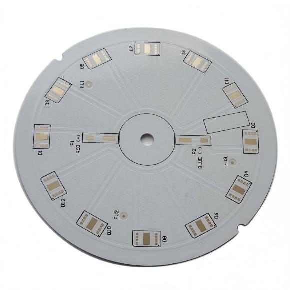
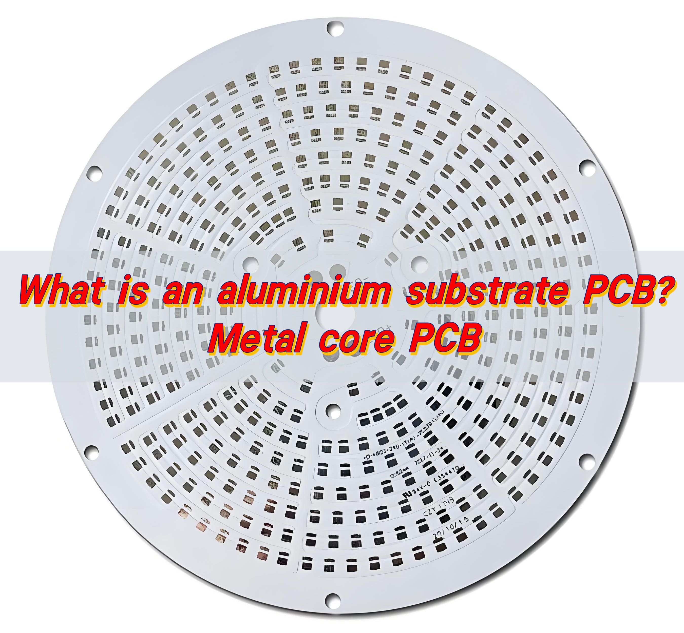
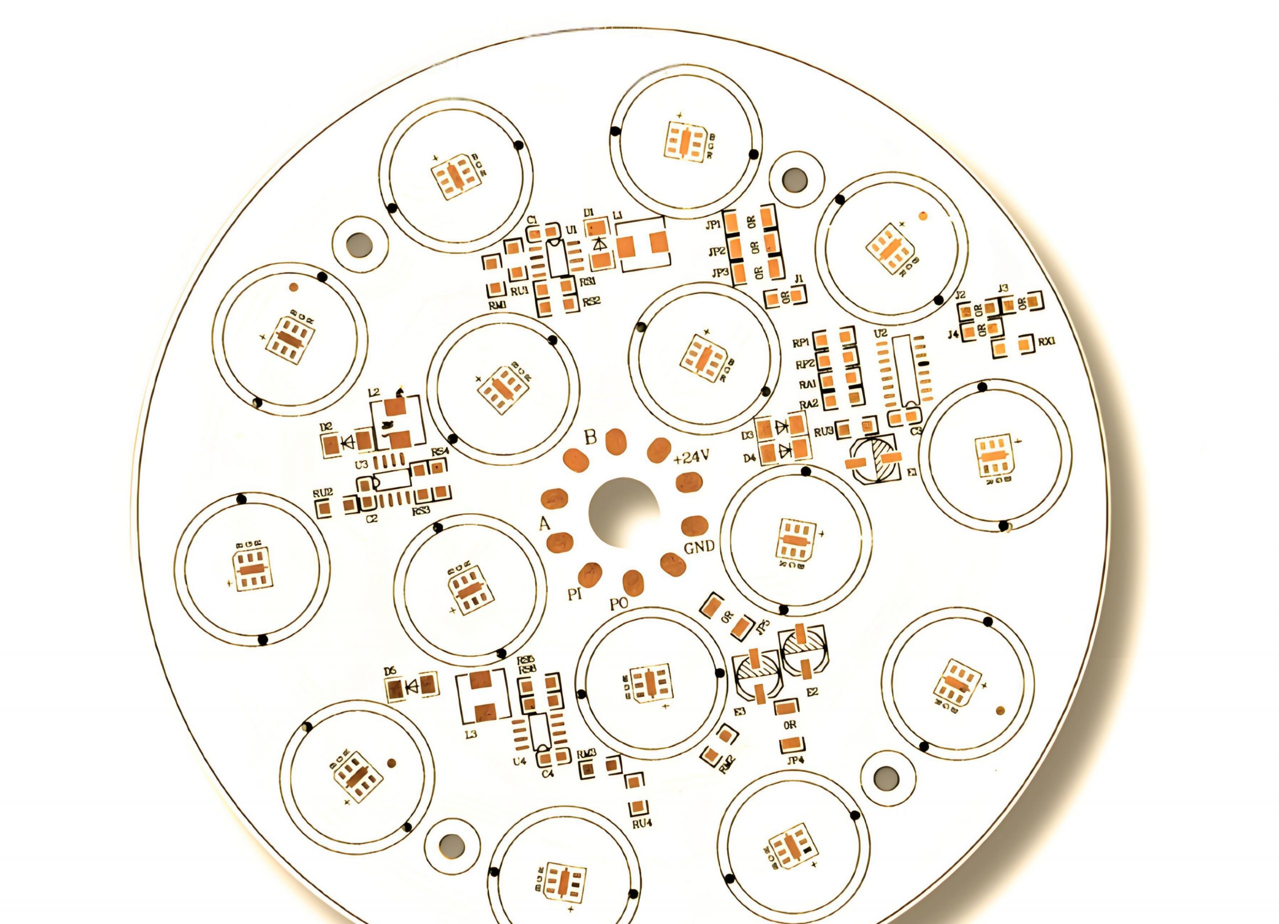
These boards are widely used in high-power LED lighting, automotive electronics, power converters, industrial control systems, and communication equipment. As power levels increase and device footprints shrink, engineers increasingly rely on aluminium core PCB, copper core PCB, and IMS PCB (Insulated Metal Substrate) technologies to stabilize thermal performance.

EBest Circuit (Best Technology)’s metal core PCB material provides excellent thermal conductivity, high stability and reliable performance for LED, power and high‑heat electronic applications.

What materials are used in metal core PCB?

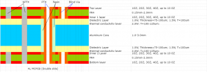
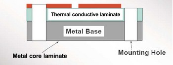
A typical metal core PCB material structure consists of three primary layers. These layers work together to transfer heat efficiently from components to the metal substrate. Each layer performs a specific thermal and electrical function that ensures stable circuit performance.

The typical MCPCB stack structure includes:

  • Copper circuit layer
  • Thermal dielectric layer
  • Metal base layer

1. Copper Circuit Layer

The top layer contains copper traces that form the electrical circuit. This layer functions similarly to the copper layer in standard PCBs. Thicker copper improves current carrying capability and also spreads heat across the board surface. Copper thickness usually ranges from:

Copper ThicknessTypical Use
1 oz (35 μm)Standard LED and low-power circuits
2 oz (70 μm)Power LED modules
3 oz – 4 ozHigh-current power electronics

2. Thermal Dielectric Layer

The dielectric layer is a critical part of metal core PCB material. It electrically isolates the circuit from the metal base while still allowing heat to pass through. High thermal conductivity dielectric materials allow heat to move quickly from components into the metal base. Typical dielectric properties include:

PropertyTypical Range
Thermal conductivity1 W/mK – 10 W/mK
Thickness50 μm – 150 μm
Breakdown voltage2 kV – 6 kV

Common dielectric fillers include:

  • Ceramic particles
  • Aluminum oxide
  • Silicon compounds

These fillers increase thermal conductivity while maintaining insulation strength.

3. Metal Base Layer

The bottom layer of a pcb metal core acts as the primary heat sink. It spreads heat over a large surface area and transfers it to the external environment. Aluminum is widely used because it provides strong thermal performance at a reasonable cost. Copper offers the highest thermal conductivity but is heavier and more expensive. The most common base materials are:

Metal Base TypeThermal Conductivity
Aluminum~200 W/mK
Copper~385 W/mK
Steel~50 W/mK

How to choose metal core PCB material?

Selecting the right metal core pcb material depends on several engineering factors. The design must balance thermal performance, mechanical strength, electrical insulation, and manufacturing cost.

1. Thermal conductivity requirement

Heat dissipation is the main reason for using IMS PCB technology. The thermal conductivity of the dielectric layer determines how quickly heat moves into the metal base. Higher conductivity improves cooling performance. Typical ranges include:

Thermal ConductivityApplication
1–2 W/mKStandard LED lighting
3–5 W/mKAutomotive lighting
5–10 W/mKHigh-power electronics

2. Electrical insulation performance

Although the metal base conducts heat well, it must remain electrically isolated from the circuit layer. Reliable insulation prevents short circuits and protects sensitive components. Designers must verify:

  • Dielectric breakdown voltage
  • Insulation resistance
  • Long-term reliability under temperature cycling

3. Mechanical stability

Mechanical strength is also important when selecting metal core PCB materials. Aluminum substrates provide good rigidity while keeping board weight low. Copper base boards offer superior strength but increase overall board mass.

4. Manufacturing compatibility

Manufacturers evaluate whether the material supports standard processes such as:

  • SMT assembly
  • reflow soldering
  • drilling and routing
  • surface finishing

A stable material simplifies production and improves yield.

Metal Core PCB Material | High Thermal Conductivity MCPCB Base Materials

What material is the MCPCB made of?

An MCPCB (Metal Core Printed Circuit Board) typically combines three major materials: copper circuitry, thermal dielectric, and a metal substrate. However, within this structure, several variants exist depending on the application.
Aluminum Core PCB

An aluminium core PCB is the most widely used type of MCPCB. Aluminum offers excellent thermal conductivity while remaining lightweight and cost-effective. Typical aluminum grades used include:

  • 5052 aluminum
  • 6061 aluminum
  • 1060 aluminum

Advantages of aluminum core PCB include:

  • Lightweight structure
  • Good heat dissipation
  • Low material cost
  • Stable mechanical properties

Because of these benefits, aluminum core boards dominate LED lighting and power modules.

Copper Core PCB

A copper core PCB uses a solid copper substrate instead of aluminum. Copper has almost double the thermal conductivity of aluminum. This allows heat to move even faster away from components. However, copper boards are heavier and more expensive. Copper core PCBs are often used in:

  • high-power LEDs
  • RF power amplifiers
  • motor drivers
  • automotive electronics

IMS PCB (Insulated Metal Substrate)

An IMS PCB refers to a board where a dielectric layer isolates the circuit from the metal base. Most metal core PCBs fall into this category. The IMS structure allows designers to combine electrical insulation with thermal efficiency.

Typical IMS stack: Copper layer → thermal dielectric → aluminum base. This structure provides excellent heat dissipation while maintaining electrical isolation.
Metal Core PCB Material | High Thermal Conductivity MCPCB Base Materials

How thick is the metal core PCB?

The metal core pcb thickness varies depending on the design requirements. Engineers must consider both electrical performance and heat transfer efficiency. A typical MCPCB includes several thickness parameters.

Total board thickness. Thicker boards often improve mechanical strength. Common board thickness values include:

Board ThicknessApplication
1.0 mmThin LED modules
1.6 mmStandard MCPCB
2.0 mmHigh-power lighting
3.2 mmPower electronics

Metal core thickness. The metal base itself can vary significantly. A thicker metal base improves heat spreading capacity.

Metal Core ThicknessTypical Range
Aluminum base0.8 mm – 3.0 mm
Copper base1.0 mm – 4.0 mm

Dielectric thickness. The dielectric layer usually ranges between: 50 μm – 150 μm. A thinner dielectric improves thermal transfer but must still provide reliable electrical insulation.
Why is thermal conductivity important in metal core PCB material?

Thermal conductivity determines how quickly heat moves through a material. In electronic circuits, efficient heat removal protects components and stabilizes performance. High temperatures can reduce LED brightness, affect semiconductor switching speed, and shorten component lifespan.
A well-designed metal core PCB material structure solves this problem by creating a direct thermal path. Because the metal base spreads heat efficiently, the board avoids localized hot spots.
Heat flows through the following stages:

  • Component generates heat
  • Heat enters copper circuit layer
  • Heat moves through dielectric layer
  • Heat spreads across metal substrate
  • Heat dissipates into air or heat sink

Typical thermal conductivity comparison:

MaterialThermal Conductivity
FR-40.3 W/mK
Aluminum base~200 W/mK
Copper base~385 W/mK

What are benefits of metal core PCB material?

The advantages of metal core pcb materials extend beyond thermal performance. Engineers often select them because they improve reliability and design flexibility. Several benefits stand out. These advantages make pcb metal core technology suitable for high-power electronics.

  • 1. Excellent heat dissipation

Metal substrates rapidly transfer heat away from components. This reduces thermal stress and improves long-term reliability.

  • 2. Improved circuit stability

Stable temperatures keep semiconductor devices operating within their optimal range.

  • 3. High mechanical strength

Metal substrates increase board rigidity and durability.

  • 4. Compact product design

Efficient heat transfer allows designers to place components closer together.

  • 5. Longer product lifespan

Lower operating temperature helps protect LEDs, ICs, and power components.

  • 6. Reduced external cooling requirements

Many MCPCB designs operate without large heat sinks.

What is the difference between metal core PCB and FR4?

A metal core PCB vs FR4 comparison highlights the fundamental differences between the two technologies.

FR-4 is a fiberglass epoxy laminate commonly used in conventional PCBs. While it offers good electrical insulation, it has limited thermal conductivity. Metal core boards replace the fiberglass base with a thermally conductive metal substrate. In applications with high power density, metal core circuit boards offer clear advantages.

Below is a comparison of the two materials.

FeatureMetal Core PCBFR-4 PCB
Base materialAluminum or copperGlass fiber epoxy
Thermal conductivityHighLow
Heat dissipationExcellentLimited
Mechanical strengthStrongModerate
WeightHeavierLightweight
Typical applicationsLEDs, power electronicsConsumer electronics
Metal Core PCB Material | High Thermal Conductivity MCPCB Base Materials

Where is metal core PCB material used?

Because of its thermal advantages, metal core PCB material appears in many modern electronic systems. Industries rely on MCPCBs to manage heat in compact designs. Common applications include:

LED lighting, High-power LEDs generate substantial heat. MCPCBs help maintain consistent brightness and extend LED life.

Examples include:

  • street lighting
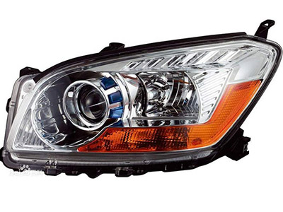
  • automotive headlights
  • industrial lighting

Automotive electronics, Vehicles require reliable thermal management for components such as:

  • engine control modules
  • power converters
  • lighting systems

Power electronics, Power supplies and converters generate high heat density. Metal core boards stabilize thermal performance in:

  • motor drives
  • DC-DC converters
  • industrial power modules

Communication systems, RF amplifiers and communication equipment often use copper core PCB structures to dissipate heat from power devices.

Consumer electronics, Compact devices such as projectors and audio equipment also benefit from MCPCB technology.

At EBest Circuit (Best Technology), we specialize in manufacturing high-quality metal core PCBs and thermal management circuit boards for demanding applications. Our engineering team supports customers from design review to production, ensuring each board meets strict performance standards.

If you are developing high-power electronic products and need reliable metal core PCB materials, feel free to contact our team. Email: sales@bestpcbs.com

You may also like

What is PCB copper core? Copper metal core PCB
Monday, August 25th, 2025

PCB copper core stands out among other PCB types due to its high thermal and power capabilities. These boards are designed to operate in harsh environments, offering exceptional durability and reliability.

What is PCB copper core? Copper metal core PCB

Maybe you have these worries and concerns:

  • Can the copper thickness and thermal conductivity of copper core PCBs be precisely tailored to meet specific requirements?
  • How can I avoid delamination and oxidation of the copper core? How can I resolve issues if they arise?
  • Can I guarantee sample or batch delivery?
  • Are there any industry examples? Can I receive a 24-hour response to after-sales technical questions?

BEST Technology can solve your problem:

  • We support custom copper thicknesses from 0.5-10 ounces, and precisely match power requirements through zoned thermal design.
  • We utilize vacuum lamination and an anti-oxidation coating (such as OSP or immersion gold) to ensure interlayer bonding strength ≥1.8N/mm² and pass 1000 cycles of -40°C to 125°C temperature cycling testing without delamination. We offer free rework or replacement for delamination and oxidation issues within the warranty period, with a 48-hour response and solution.
  • Single- and double-sided boards: 24-48 hours, multi-layer boards: 3-5 days. Batch delivery: Regular orders: 7-10 days, expedited orders: within 3 days.
  • This material has been widely used in new energy vehicle BMS systems (10oz copper thickness), industrial inverters (8oz multilayer boards), and 5G base station power modules (6oz copper core). We provide 24-hour remote support to ensure rapid resolution of technical issues.

What is a copper core PCB?

Copper core PCB is a type of printed circuit board with a solid copper layer at its core. Unlike traditional PCBs, where copper is only part of the circuit paths, the core itself is copper. This provides superior thermal conductivity, allowing heat to be efficiently managed in high-power applications.

The copper core acts as a heat spreader. It moves heat away from sensitive components. This prevents overheating and maintains long-term performance. These boards are widely used in LED lighting, automotive electronics, industrial equipment, and power electronics.

Using a copper core also improves the mechanical stability of the board. Components remain securely in place even under heat stress. The copper’s high conductivity ensures that both electrical performance and heat dissipation are optimal.

Why Use a Copper Core PCB?

Modern electronics often produce significant heat, which can reduce efficiency and shorten the life of components. Copper core PCBs solve this problem efficiently.

Here’s why they are used:

  • High thermal conductivity: Copper efficiently transfers heat away from components, keeping devices cooler.
  • Durability: They withstand thermal cycling better than standard FR4 boards.
  • Compact design: Designers can place components closer together without worrying about overheating.
  • Energy efficiency: Reduced heat buildup enhances performance and reduces energy loss.

In short, using a copper core PCB increases reliability, extends device life, and supports high-power applications where traditional PCBs would fail.

How is a Copper Metal Core PCB Made?

The manufacturing of a copper metal core PCB differs from standard PCB production. It requires precision and advanced techniques.

What is PCB copper core? Copper metal core PCB

Step-by-step process:

  • Copper sheet selection: High-purity copper sheets are chosen for the core. Purity ensures consistent thermal conductivity.
  • Insulation layer application: An insulating dielectric layer is added to separate the copper core from the circuit traces.
  • Copper layering: Copper foil is laminated on both sides of the dielectric layer. This creates the circuit paths.
  • Etching: The unwanted copper is chemically removed to form the desired circuit design.
  • Surface finish: Methods like HASL, ENIG, or immersion silver are applied to protect the copper and improve solderability.
  • Testing and inspection: Each board is rigorously tested for electrical continuity, thermal performance, and mechanical stability.

This process ensures that copper core PCBs perform well under high thermal and electrical stress.

Do PCBs Have Copper?

Yes, copper is a standard material in all PCBs. It forms the conductive pathways that carry electricity. Standard FR4 PCBs use copper only in traces and pads.

Copper core PCBs are different. The copper is in the core, not just the circuit layers. This gives them superior heat conduction. Components stay cooler, even under heavy loads.

Copper’s excellent electrical and thermal conductivity ensures stable performance. Devices work reliably for years without overheating.

What Type of Copper is Used in PCB?

The type of copper affects both thermal and electrical performance. In copper core PCBs, BEST Technology typically use:

  • High-purity electrolytic copper: Provides consistent conductivity and low resistance.
  • Oxygen-free copper (OFC): Reduces oxidation and ensures long-term stability.
  • Rolled annealed copper: Offers flexibility and mechanical strength for assembly.
What is PCB copper core? Copper metal core PCB

Choosing the right copper type ensures high thermal conductivity, strong mechanical support, and stable electrical performance. This is especially important in LEDs, automotive electronics, and industrial equipment.

The Types of Copper-Based PCB

Copper-based PCBs can vary depending on the application. The main types include:

  • Single-layer copper core PCB: Features one conductive layer. Often used in simple LED modules or low-power devices.
  • Double-layer copper core PCB: Has copper on both sides. This design supports more complex routing while maintaining heat management.
  • Multilayer copper core PCB: Includes multiple circuit layers with a central copper core. Ideal for high-power, dense electronics.
  • Flexible copper core PCB: Thin copper sheets with flexible substrates allow heat dissipation and adaptable design.

Each type is tailored for specific needs. LEDs often use single or double-layer boards. Industrial and automotive applications prefer multilayer copper core PCBs.

Is Copper Core or Aluminum Core Better?

Both copper and aluminum core PCBs are designed to manage heat efficiently. However, copper offers several advantages.

Advantages of copper core:

  • Higher thermal conductivity.
  • Better electrical performance.
  • Greater long-term reliability.

Advantages of aluminum core:

  • Lower cost.
  • Lightweight construction.
  • Suitable for moderate heat applications.

While aluminum cores are cost-effective, copper core PCBs outperform them in thermal management, reliability, and longevity. This makes copper the preferred choice for high-power and high-reliability electronics.

Copper Core vs Aluminum Core – Thermal Conductivity

Thermal conductivity determines how efficiently a material transfers heat. This is critical in electronics design.

  • Copper core PCB: Typically 300–400 W/m·K.
  • Aluminum core PCB: Typically 1-30 W/m·K.
What is PCB copper core? Copper metal core PCB

Copper conducts heat several times faster than aluminum. This keeps components cooler and prevents hotspots. Electronics run efficiently and last longer when heat is managed properly.

Conclusion:

PCB copper core ensures excellent thermal conductivity. Components stay cool, even under high power or prolonged use. Copper core PCBs are durable, reliable, and suitable for compact designs. Compared to aluminum, they provide higher conductivity, better performance, and longer lifespan.

These boards are widely used in LED lighting, automotive electronics, industrial equipment, and power modules. Choosing a copper core PCB improves efficiency, safety, and product reliability.

For more information or inquiries, contact sales@bestpcbs.com

You may also like

Copper Core PCB vs Aluminum PCB: How to Choose the Right One? – Series 2
Saturday, May 24th, 2025

In our last blog, we introduced the definition and basic of copper core PCB. But copper core PCB isn’t the only one metal core PCB, aluminum PCB provides good heat dissipation as well. So, when working with metal core boards, many engineers and buyers are unsure whether to choose an aluminum PCB or a copper core PCB. Some believe copper is always better, while others go with aluminum for lower cost. Today, we will guide you how to choose them, then let’s start it!

Material Comparison: Copper vs Aluminum Core

Both copper and aluminum are used as the core material for thermal management in PCBs, but their physical and electrical properties differ significantly:

PropertyCopperAluminum
Thermal Conductivity~380–400 W/m·K~200–230 W/m·K
Electrical Conductivity~58 MS/m~35 MS/m
Density8.96 g/cm³2.70 g/cm³
StrengthHigher rigidityMore flexible
Cost1.5x to 3x higherLower

Copper provides superior conductivity and better rigidity but comes at a much higher cost and weight. Aluminum is lighter, easier to machine, and cost-effective for mid-range applications.

Thermal Management: Which One Handles Heat Better?

When heat dissipation is your top priority, copper clearly wins. Its high thermal conductivity allows heat to spread faster and more evenly, which is critical in high-power applications like:

  • LED floodlights and stadium lighting
  • Automotive headlights
  • Power converters and inverters
  • Laser driver modules

Case example: A customer replaced an aluminum PCB with a copper base for a 100W LED driver. The operating temperature dropped by 15°C, drastically improving product lifespan.

However, in low-to-mid power systems—like ceiling lights, LED bulbs, or camera light rings—aluminum is typically sufficient. Using copper in these cases is often unnecessary and drives up costs without clear benefits.

Mechanical Strength and Weight: What Does Your Design Need?

Copper core PCBs are heavier and more rigid, which makes them better for industrial applications exposed to vibration or extreme temperature cycles.

But in products where weight matters—like drones or wearable devices—aluminum PCBs are the smarter option. They are easier to machine, route, and assemble. They also cost less in terms of tooling and manufacturing time.

Choose copper core PCBs if you need:

  • High mechanical stability
  • Vibration resistance
  • Long-term thermal durability

Choose aluminum PCBs if your product needs:

  • Lightweight design
  • Cost control
  • Simpler routing and drilling

Cost Consideration: Is Copper Always Worth It?

Let’s be honest: copper core PCBs can cost up to 3x more than aluminum PCBs. So you should ask yourself—is the higher thermal performance really necessary for your design?

Aluminum PCBs are the better choice when:

  • Your application doesn’t exceed 80W–100W
  • Weight and cost are design priorities
  • You’re in mass production and need price stability

Copper core PCBs are justified when:

  • Your system needs to handle heavy heat loads
  • High current density is involved
  • Long-term reliability matters more than price

Many of our customers reduce total project cost by switching to aluminum PCBs without sacrificing performance—once we review their thermal simulation data.

Where to Use Each PCB Type?

Here’s a quick-reference table to match your application with the recommended base material:

ApplicationRecommended BaseReason
High-power LED floodlightsCopperHeat and current requirements are high
Automotive lighting systemsCopper or thick aluminumPerformance and safety critical
Indoor LED lightingAluminumLower heat, cost-sensitive
Power modules & invertersCopperHigh voltage and thermal stress
Camera flash or ring lightAluminumLightweight and cost-friendly
Medical power supplyCopperStability and safety required
LED floodlights (150W+)Copper Core PCBHandles heat better
LED bulbs & home lightingAluminum PCBAffordable and thermally sufficient
EV chargers & power modulesCopper Core PCBHigh reliability under load
Camera flashes & portable lightsAluminum PCBLightweight and budget-friendly
Medical devices (power control)Copper Core PCBPrecise, stable performance
Consumer electronicsAluminum PCBCost-efficient for large volumes

Use this guide to avoid over-engineering or under-specifying your metal core PCB.

5 Key Points Before You Choose

Still not sure which base material fits your needs? Walk through this five-step checklist:

1. Power Level: How much current and heat does your circuit handle?

2. Installation Environment: Is weight a constraint? Will it face vibration?

3. Target Cost: Are you selling a premium or mass-market product?

4. Design Complexity: Do you need tight tolerances or complex routing?

5. Volume & Lead Time: Can your supplier meet deadlines for the material?

If you answered “high” for performance on most points, copper is likely the way to go. If not, aluminum is your best cost-performance choice. By the way, if you’re unsure after answering these, consult with your PCB manufacturer. At EBest Circuit (Best Technology), we provide application-based advice to help you choose between aluminum PCBs and copper core PCBs—without overspending.

Why Choose EBest Circuit (Best Technology) for Your Metal Core PCB?

Whether you need aluminum base PCBs for standard lighting or copper base PCBs for high-power industrial applications, EBest Circuit (Best Technology) has you covered:

  • Mature production lines for both copper and aluminum base PCBs
  • One-on-one design support, thermal simulation, and DFM reviews
  • Full in-house capabilities: thick copper etching, CNC routing, V-cutting
  • Fast sample turnaround and stable mass production support
  • Strict quality control and traceability through MES system
  • Expert engineering team for application-specific advice

Reach out to EBest Circuit (Best Technology)—we’ll help you analyze your application, recommend the ideal PCB solution, and even support custom development if needed.

FAQs

Q1: Can I use aluminum base PCBs for high-power applications?

Only for moderate heat loads. For >100W power systems, copper is strongly recommended.

Q2: What is the thinnest aluminum or copper base you can provide?

We can produce down to 0.8mm base thickness for both, depending on the structure.

Q3: Do you offer hybrid metal core PCBs?

Yes, we can integrate aluminum and FR4 or support copper-ceramic hybrid designs.

Q4: How long is the lead time for copper vs aluminum base?

Aluminum PCBs: 5–7 working days; Copper PCBs: 7–12 days depending on complexity.

Q5: Can I get thermal simulation before placing an order?

Absolutely! We offer pre-production thermal analysis and structural design assistance.

Q6: Are copper core PCBs compatible with standard SMT processes?

Yes, they are. We offer full SMT assembly services for both aluminum and copper base boards.

Q7: How do I know which type is best for my application?

Send us your design or specs, and we’ll recommend the most cost-effective and reliable option.

Conclusion

Choosing between a copper core PCB and an aluminum PCB isn’t about choosing the better material. It’s about selecting what’s right for your application. Copper is powerful but expensive; aluminum is flexible and affordable.

When designed and selected correctly, aluminum PCBs can outperform expectations, and copper core PCBs can save your system from thermal failure. Match the material to your environment, budget, and performance goals—and you’ll never go wrong. In our next blog, we will share how to select the thickness of copper. If you are interested in it, collect us and keep reading.

You may also like

Is Copper Base PCB Right for You? – Series 1
Friday, May 23rd, 2025

Copper base PCBs have become increasingly popular in high-power and thermally demanding applications. But many customers still ask: “Is it really suitable for my project?” If you’re in LED lighting, power electronics, automotive, or any field requiring excellent heat dissipation, this article is for you. We’ll walk you through what copper base PCBs are, their key advantages, and how to determine whether they’re the right fit for your product.

What Is a Copper Base PCB?

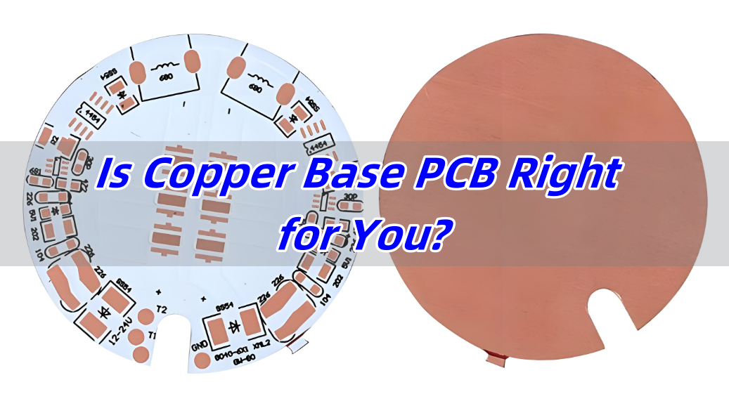
A Copper Base PCB is a type of metal core printed circuit board (MCPCB) that uses copper as the base material instead of the more common aluminum or FR4. This type of board is specifically designed to handle high heat, high power, and mechanical stress. The copper base acts as a heat sink, pulling heat away from components and distributing it more evenly. Compared with FR4 PCB, copper PCBs offer superior heat conductivity, mechanical strength, and current-carrying capacity.

Typical Structure of a Copper Base PCB

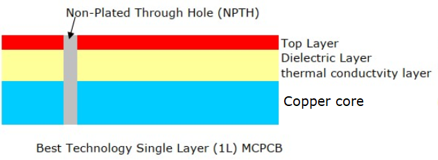
The structure of a copper base PCB is generally composed of three main layers, each playing a critical role in the board’s performance:

  • Copper Circuit Layer (Top Layer):

This layer contains the etched copper traces that form the electrical pathways. In copper base PCBs, this layer is often thicker than in standard PCBs—ranging from 1 oz to 20 oz or more—to handle higher current loads and improve heat distribution. These traces can be plated or coated depending on the application or customers requirements (e.g., ENIG, HASL, OSP).

  • Thermal Dielectric Layer (Middle Layer):

This is the insulating layer between the circuit and the metal base. It’s designed to have high thermal conductivity and excellent electrical insulation. Its main function is to transfer heat from the components to the copper base below while keeping the circuits electrically isolated. The thermal conductivity of this layer often ranges from 1 W/m·K to over 10 W/m·K, depending on material choice.

  • Copper Base Layer (Bottom Layer):

Unlike typical MCPCBs that use aluminum, this layer is made of solid copper—usually ranging from 1 mm to 3.5 mm thick or more. This acts as a heat sink, pulling heat away from the circuit layer and rapidly dispersing it. Copper’s thermal conductivity is about 400 W/m·K, significantly higher than aluminum (~200 W/m·K).

This design structure enables heat to be quickly conducted from the components to the copper baseplate, and then transferred through the heat sink or the casing, thereby enhancing the overall thermal management capability of the system.

What Are the Core Advantages of Copper Base PCBs?

Clients often wonder: “Why should I pay more for a copper base board?” Here’s why it might be worth it:

  • Exceptional thermal conductivity – Copper is far more effective at dissipating heat than aluminum or FR4, very suitable for high-wattage components.
  • High current tolerance – With thicker copper layers, these PCBs handle larger currents with minimal resistance.
  • Excellent mechanical durability – Copper PCBs are stronger and can withstand physical stress, vibration, and temperature cycling.
  • Improved electromagnetic shielding – Their dense base helps suppress EMI, a critical benefit in high-frequency applications.

These benefits result in longer product life, more consistent performance, and fewer field failures, especially in mission-critical applications.

Which Industries Benefit Most from Copper Base PCBs?

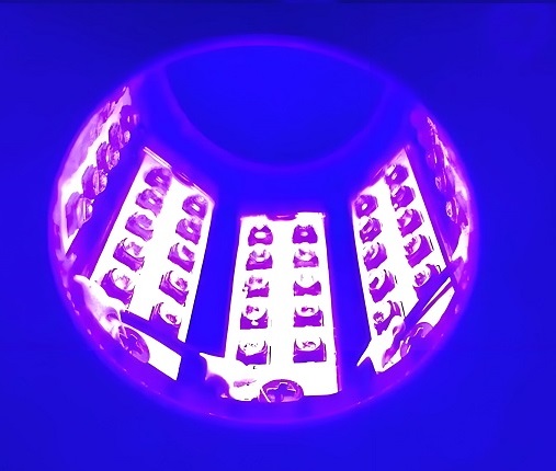
  • LED Lighting – High-power LEDs like COB, UV LED, floodlights, and grow lights require efficient thermal management.
  • Power Electronics – Power supplies, inverters, and converters benefit from copper’s high current-carrying capacity.
  • Automotive – EV batteries, headlights, and control systems need durability and consistent heat dissipation.
  • Telecom & RF Devices – Copper PCBs handle high frequencies with reduced signal loss and better EMI shielding.
  • Medical Equipment – High reliability is key for precision instruments that cannot afford overheating.

If your product involves heat, high power, or harsh environments, copper base PCBs are often the most dependable choice.

How Can You Tell If a Copper Base PCB Is Right for Your Project?

Before committing, ask yourself the following:

1. Does your design generate significant heat?

2. Is there limited space, but high power density?

3. Are you struggling with product reliability or failures due to overheating?

4. Is your end-product used in mission-critical or high-reliability environments?

If you answered “yes” to two or more of these, a copper base PCB could greatly improve your performance and reliability.

What Are the Limitations or Considerations of Copper Base PCBs?

While copper base PCBs offer outstanding thermal and electrical performance, they are not suitable for every project. Understanding their limitations and key design considerations is essential to avoid overdesign, unnecessary costs, or compatibility issues in your application.

1. Higher Material and Production Cost

Copper is significantly more expensive than aluminum or fiberglass (FR4). This cost factor affects both raw material pricing and manufacturing expenses. Additionally, the thicker copper layers and heavier base not only cost more to source, but they also require more energy and effort to process, increasing the total cost of production.

2. Heavier Board Weight

Copper has a high density (8.96 g/cm³ compared to aluminum’s 2.70 g/cm³), which means copper base PCBs are substantially heavier. This can present challenges in:

  • Weight-sensitive products such as drones or handheld devices
  • Shipping and logistics costs, especially for large quantities
  • Mechanical handling in assembly lines

Tip: If you’re designing a compact or mobile device, consider whether the weight trade-off justifies the thermal benefit.

3. More Challenging to Fabricate and Process

Due to the hardness and thickness of the copper base, special tooling, slower machining speeds, and experienced operators are required. Fabricators must use tougher drill bits, precise CNC machines, and advanced lamination processes to ensure:

  • Clean drill holes
  • Accurate etching and layering
  • Strong adhesion between layers

Poor processing can result in delamination, cracks, or electrical leakage—especially at the dielectric interface.

4. Limited Flexibility in Complex Layer Stack-Ups

While single-layer copper PCBs are common, multi-layer copper base PCBs are difficult and expensive to produce. This is because:

  • Each additional layer increases complexity in lamination
  • Heat must still flow effectively through the stack
  • Alignment and insulation tolerance become more critical

Not all manufacturers offer multi-layer copper PCBs due to the strict processing requirements and lower production yields.

5. Thermal Expansion and Stress Considerations

Copper has a relatively low coefficient of thermal expansion (CTE), which is good for dimensional stability. However, when paired with dielectric materials or mounted in assemblies with mismatched CTEs, thermal stress can build up during repeated heating and cooling cycles.

This can lead to:

  • Micro-cracking
  • Solder joint fatigue
  • Mechanical warping of the board

If you need help evaluating whether copper base PCBs are the right choice for your next project, EBest Circuit (Best Technology)’s engineering team is here to offer thermal simulation, design review, and cost-performance optimization—so you only pay for what you truly need.

Why Choose EBest Circuit (Best Technology) for Your Copper Base PCBs?

When it comes to copper base PCBs, expertise matters. At EBest Circuit (Best Technology), we provide end-to-end solutions — from thermal simulation and material selection to rapid prototyping and mass production.

Why choose us?

✅ One-on-one engineering support

✅ In-house thermal and mechanical design assistance

✅ Certified quality (ISO9001, ISO13485, IATF16949, AS9100D)

✅ MES system for full traceability

✅ On-time delivery and competitive pricing

Let us help you build reliable, high-performance PCBs tailored to your application needs.

Frequently Asked Questions (FAQs)

Q1: Is copper base PCB better than aluminum base for heat dissipation?

Yes, copper offers superior thermal conductivity compared to aluminum and handles higher thermal loads.

Q2: What thicknesses are available for copper base PCBs?

Copper thickness typically ranges from 1oz to 20oz or more depending on your current/thermal needs.

Q3: Can copper base PCBs support multi-layer structures?

Yes, although complex and costly, multi-layer copper base PCBs are feasible with the right process control.

Q4: How can I improve thermal performance in my copper PCB design?

Use thermal vias, select high-conductivity dielectric layers, and optimize component placement.

Q5: Why is copper base PCB more expensive?

Copper material, heavier base layers, and specialized manufacturing processes contribute to the higher cost.

You may also like

Do You Know Who Is the King Among the Metal Core PCBs?
Saturday, October 14th, 2023

Have you ever encountered these problems: your LED beads overheat, lose brightness, and shorten their lifespan? Have you ever thought of using a better PCB material to solve these problems?

If you are considering this question and your answer is yes, then you must learn about thermal-electric separation copper PCB, the king of Metal Core PCB (MCPCB), which can make your LED lamps achieve unprecedented effects.

What is Metal Core PCB?

It is a type of printed circuit board that uses metal material as the heat dissipation layer, commonly used in LED and other high-power electronic products. There are many types of metal core PCB, among which the most common one is aluminum PCB, which has a thermal conductivity of about 1W, suitable for low-power LED lamps.

However, with the development of high-power electronic products and high-frequency PCBs, aluminum PCBs can no longer meet the requirements of heat dissipation and volume. Therefore, more and more products choose copper PCB, which has a thermal conductivity of up to 400W, 400 times that of aluminum PCB. But ordinary copper PCB also has a drawback, that is, its circuit layer and heat layer are on the same layer, which requires connecting the beads and the heat layer through an insulating thermal conductive material, which will reduce the thermal efficiency. To solve this problem, a more advanced copper PCB structure has emerged, called thermal-electric separation copper PCB or SinkPad PCB.

(Thermal_electric_separation_copper_pcb)

Introduction to Thermal-electric Separation Copper PCB

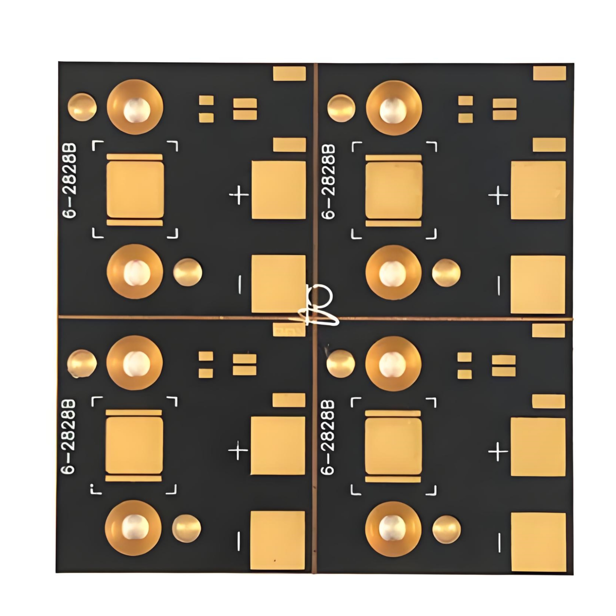
The feature of thermal-electric separation copper PCB is that its circuit layer and heat layer are on different layers so that the beads can directly contact the heat layer, achieving zero thermal resistance heat dissipation. This structure can greatly improve the luminous efficiency and lifespan of the beads, and reduce light decay and heating. Thermal-electric separation copper PCB is very suitable for single high-power beads, especially the COB package, which can make the lamp achieve better effects. In addition, thermal-electric separation copper PCB can also be made into different shapes and structures according to different design needs, such as copper protrusions, copper recesses, parallel heat dissipation, etc.

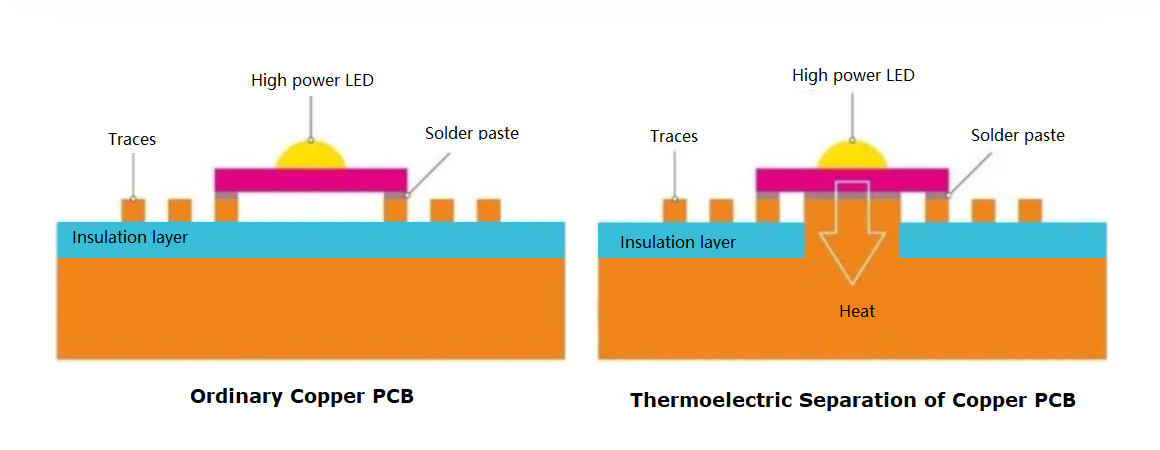
Below is the structure diagram of ordinary copper PCB and copper substrate bump thermoelectric separation as an example to give you a more intuitive understanding of the advantages of thermoelectric separation copper substrate processing technology.

(Diagram_structure_comprasion)

From the ordinary copper PCB diagram on the left, it can be seen that the heat dissipation needs to pass through the insulating and thermally conductive material (purple part in the picture), which is more convenient to process. However, after passing through the insulating and thermally conductive material, the thermal conductivity is not so good. This kind of suitable for low-power LED lights, which is enough.

If the heat dissipation requirements are very large on automotive LED lamp beads or high-frequency PCBs, both normal aluminum PCB and copper core PCB cannot meet the requirements. It is common to use thermoelectric separation of copper substrates. Because the circuit trace and thermal layer are on the different layers, the thermal layer part directly contacts the LED beads (as shown on the right side of the picture above) to achieve the best heat dissipation (zero thermal resistance) effect.

Besides, there are also many various surface treatment options for the thermal electric separation copper PCB, such as OSP, immersion gold, ENIG, immersion silver, silver plating, ENEPIG, etc. It can be carried out according to different needs, and the surface treatment layer and lifespan are reliable.

Who Can Make Thermal-electric Separation Copper PCB for You?

When you are considering to sample or order thermal-electric separation copper PCBs, it is recommended to choose EBest Circuit (Best Technology). Best team is a professional PCB manufacturer who specializes in PCB manufacturing for over 17 years of experience and provides excellent before and after-sales service. Now, EBest Circuit (Best Technology) highly recommends thermal-electric separation copper PCB for you, and the price is very favorable right now. And we promise that we will make satisfactory thermal-electric separation copper PCB for you with the fastest speed and the highest quality. This is what we are proud of.

If you have any questions or comments about thermal-electric separation copper PCB or more information about our company, please feel free to contact us or e-mail us at sales@bestpcbs.com. We will serve you wholeheartedly.

You may also like

What is SinkPad PCB?
Wednesday, June 17th, 2020

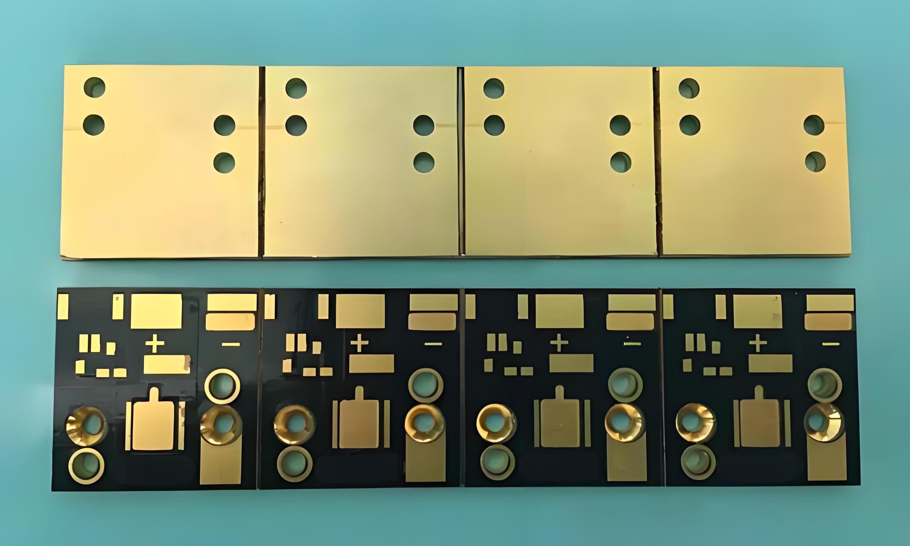
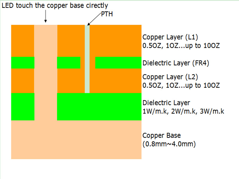
SinkPad PCB, also called Heat Sink or DTP (direct thermal path) PCB, it is a type of Copper base PCB used in thermoelectric separation application. It generally used for high power LED, the pad of LED touch the copper base directly, so that the heat generated by LED will dissipate quickly, which can achieve the best heat dissipation and conduction.

SinkPad PCB
SinkPad PCB

Thermoelectric separation technology is based on the higher heat dissipation requirements of high power electronic products, which needs to meet two basic conditions:

1.LED pad touches the base substrate directly.

It means we need to increase the path of the LED pad to the base substrate to accelerate the heat emission from the base material.

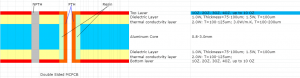
Two layers SinkPad PCB Stack up

2.Higher heat dissipation substrate materials

Copper has a thermal conductivity of 401W/m·K, while aluminum has a thermal conductivity of 237W/m·K. Obviously, copper has better thermal conductivity because of its high density, high mass. Therefore, a SinkPad PCB usually means a SinkPad copper base PCB.

You may also like