PCB manufacturing PCB manufacturing
Home > Blog

laser direct imaging

Laser Direct Imaging in PCB Manufacturing: Process, Solder Mask, Benefits, and Applications
Tuesday, July 28th, 2026

Laser direct imaging, or LDI, transfers PCB circuit and solder mask patterns directly from digital production data onto photosensitive material. Unlike conventional exposure, it does not rely on a physical film phototool. A laser direct imaging PCB workflow uses digital production data instead of a physical mask.

This gives the PCB manufacturer more control over image scaling, alignment, and panel distortion. The process is particularly useful for HDI boards, fine-line multilayer PCBs, flexible circuits, dense BGA designs, and boards with tight solder mask registration.

LDI is not necessary for every PCB. Conventional imaging may still be suitable for boards with wider traces, generous spacing, stable materials, and relaxed registration tolerances. The correct choice depends on the design rather than the layer count alone.
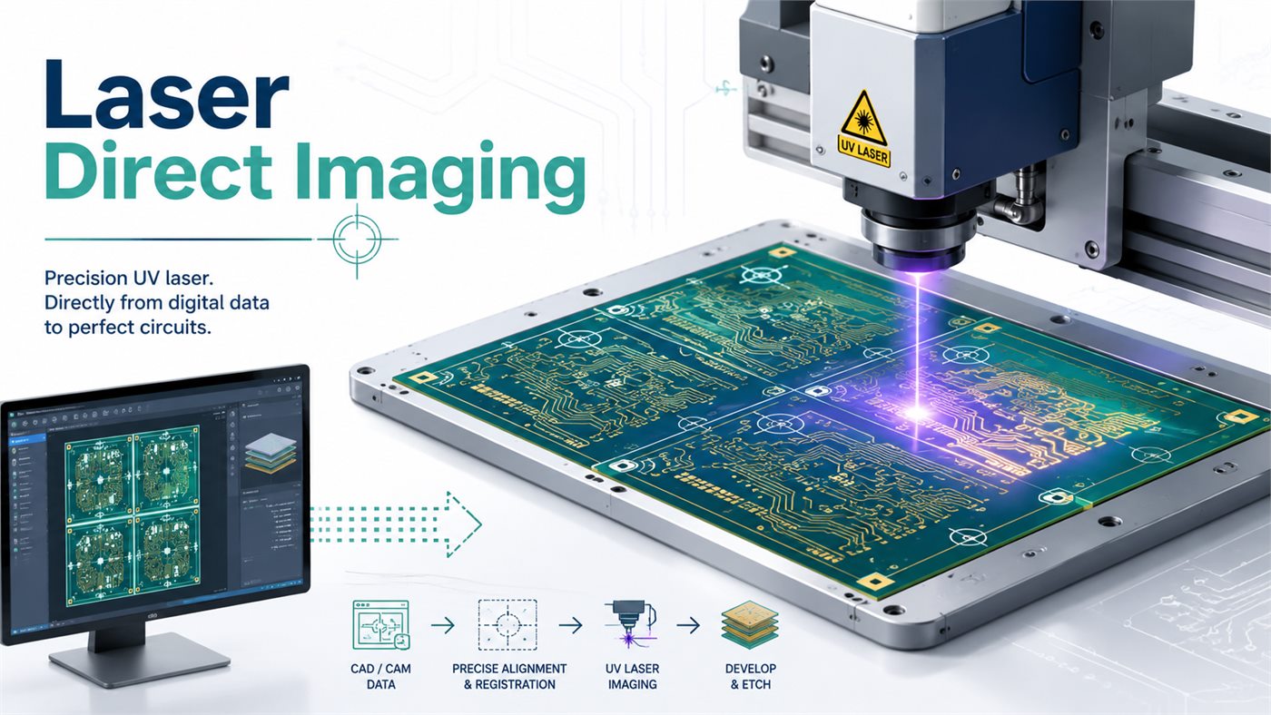
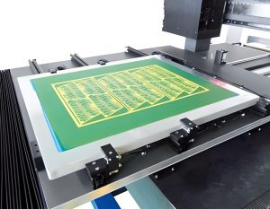
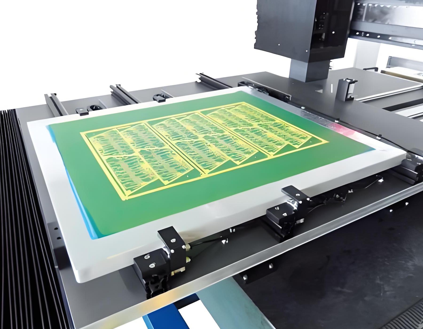
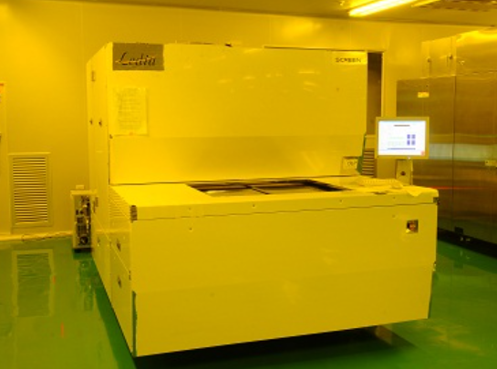
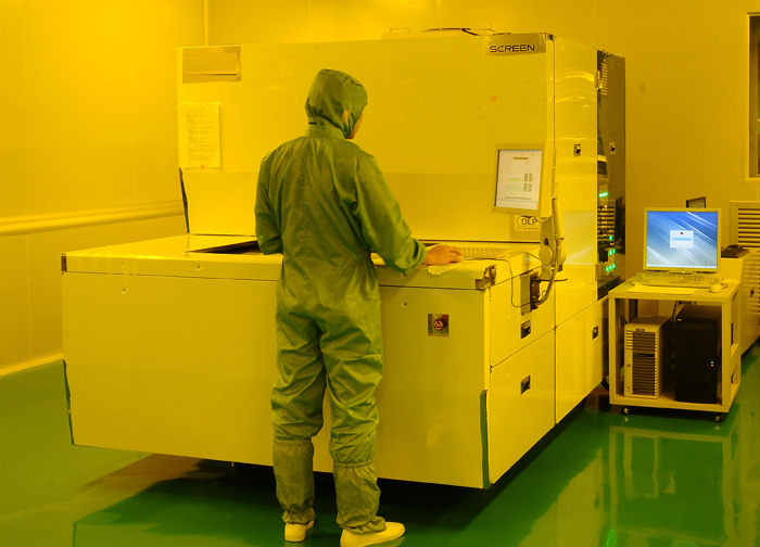
Laser direct imaging machine exposing a PCB panel from digital CAM data

What Is Laser Direct Imaging (LDI)?

Laser direct imaging is a digital PCB exposure process. An LDI machine reads CAM data generated from Gerber or ODB++ files and exposes the required pattern directly onto photoresist or liquid photoimageable solder mask. A physical film mask is not required.

LDI may be used for:

  • Inner-layer circuit imaging
  • Outer-layer circuit imaging
  • HDI build-up layers
  • Pattern-plating processes
  • Solder mask exposure
  • Flexible and rigid-flex circuits
  • Fine-line package substrates

LDI does not remove copper or drill holes. It creates the photosensitive pattern that controls later developing, etching, plating, or solder mask processing.

How Does Laser Direct Imaging Work?

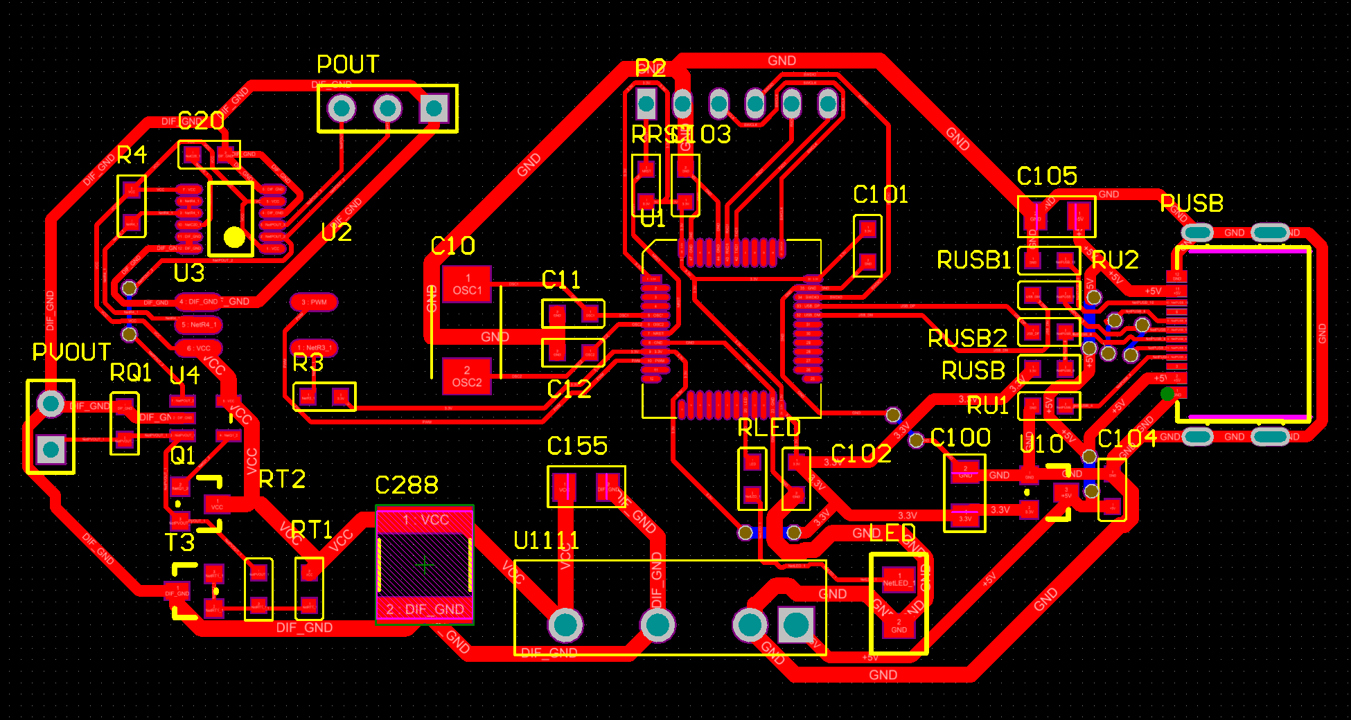
The process begins with digital PCB artwork. CAM software converts the production data into exposure instructions for the LDI system.

Before imaging, registration cameras locate targets on the PCB panel. The machine compares their actual positions with the design coordinates and may correct:

  • X-Y position
  • Rotation
  • Image scale
  • Panel expansion or shrinkage
  • Local dimensional distortion

The system then exposes selected areas of the photosensitive coating with controlled ultraviolet light. After exposure, the panel enters the developing process. Soluble resist is removed, leaving the required circuit or solder mask image.

This digital correction is one of the main reasons LDI is useful for advanced PCBs. Panels can change slightly during lamination, heating, copper plating, or flex-material processing. A fixed phototool cannot easily adapt to those changes, while an LDI image can be adjusted before exposure.

What Is the Step-by-Step LDI PCB Imaging Process?
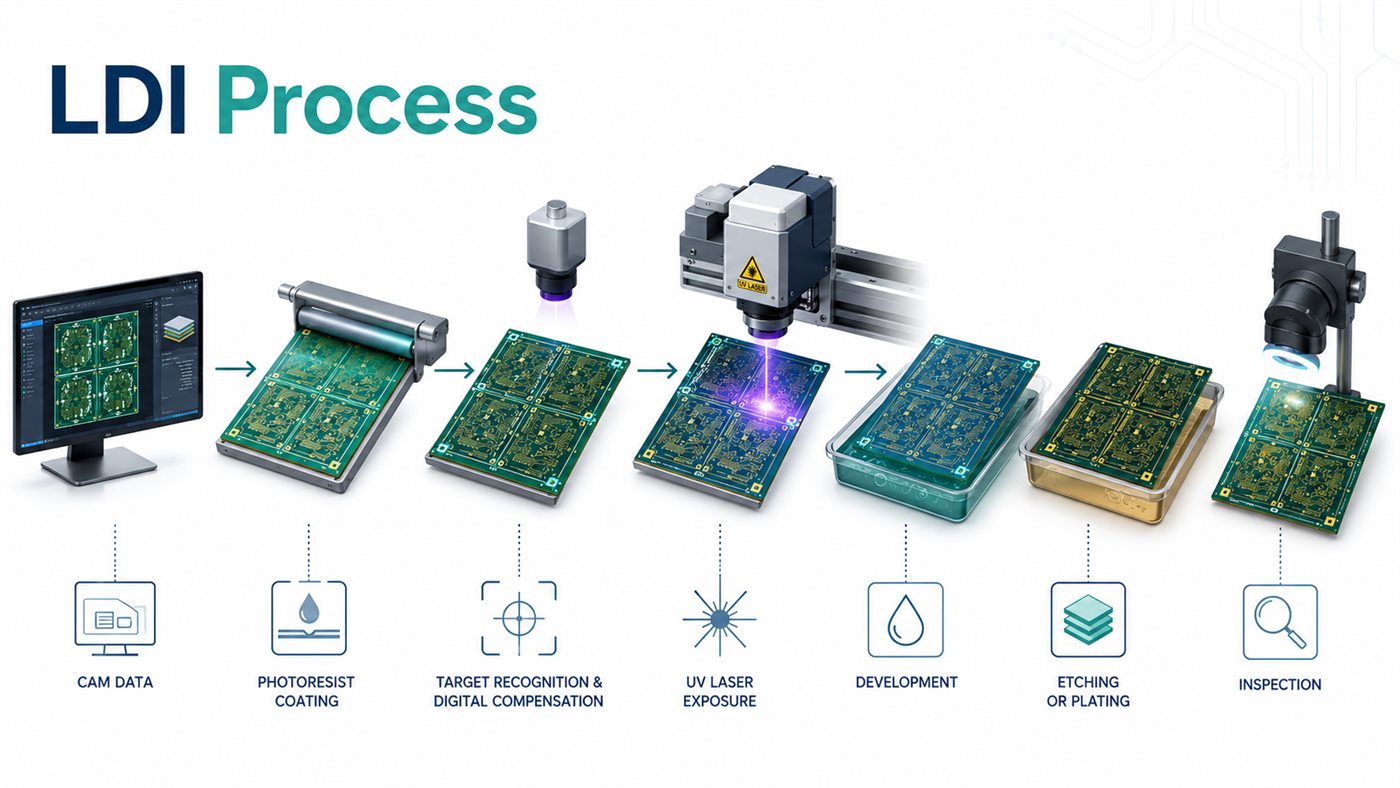
Step-by-step LDI PCB imaging process from CAM data to inspection

The exact workflow varies between inner layers, outer layers, and solder mask, but the main sequence is similar.

  1. CAM preparation: Engineers check layer polarity, panelization, tooling targets, scaling, and manufacturing compensation.
  2. Surface cleaning: Copper is cleaned and, when required, micro-etched. Dust, oxidation, oil, or fingerprints can weaken resist adhesion.
  3. Photoresist application: Dry-film photoresist is laminated onto copper. For solder mask, liquid photoimageable material is coated and tack-dried.
  4. Target recognition: Cameras locate tooling holes, etched targets, or fiducials on the panel.
  5. Digital compensation: Software adjusts the exposure image to match the actual panel dimensions.
  6. Laser exposure: The LDI system writes the circuit or solder mask pattern onto the photosensitive layer.
  7. Development: The soluble part of the resist is removed, revealing the required pattern.
  8. Etching or plating: Inner layers normally proceed to etching. Outer layers may enter pattern plating before final etching.
  9. Resist stripping: Temporary circuit resist is removed after completing its masking function.
  10. Inspection: AOI or solder mask inspection checks for opens, shorts, missing features, registration errors, and unwanted mask coverage.

LDI improves image placement, but it cannot correct poor cleaning, unstable development, excessive etching variation, or unsuitable photoresist.

What Are the Main Components of a Laser Direct Imaging System?
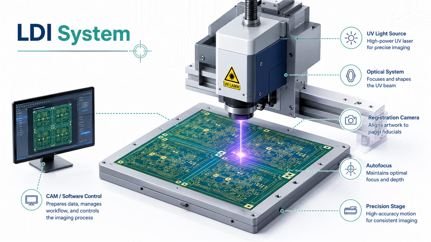
Main components of an LDI system including UV source, optics, registration camera, autofocus, stage, and CAM control

An LDI machine combines imaging, optical, motion-control, and data-processing systems. Its main components normally include:

  • UV light source: Supplies exposure energy.
  • Optical system: Directs and focuses the light.
  • Image-modulation unit: Controls which areas are exposed.
  • Registration cameras: Detect panel targets.
  • Precision stage: Positions the panel or imaging head.
  • Autofocus system: Adjusts for panel thickness and surface variation.
  • CAM software: Converts PCB data into exposure instructions.
  • Handling system: Loads, aligns, turns, and unloads panels.
  • Environmental controls: Reduce dust, vibration, and temperature variation.

Equipment model alone does not prove manufacturing capability. PCB buyers should focus on stable line width, spacing, registration tolerance, supported materials, qualified resist systems, and volume-production performance.

What Photoresist Is Used for Laser Direct Imaging?

Circuit imaging usually uses dry-film photoresist designed for the wavelength and energy output of the LDI machine. A laser direct imaging photoresist must match the exposure wavelength and process energy. Liquid photoimageable materials are more commonly used for solder mask.

A suitable LDI photoresist should provide:

  • Compatibility with the exposure wavelength
  • Adequate photospeed
  • Strong adhesion to prepared copper
  • Resolution for the required line and space
  • Resistance to etching or plating chemistry
  • Clean developing and stripping
  • Stable tenting over holes, when required
  • A practical manufacturing process window

Common LDI systems operate with ultraviolet wavelengths such as 355 nm or 405 nm. Some equipment supports multiple wavelengths to improve compatibility with different resist systems.

The advertised resolution of a dry film should not be treated as the finished PCB capability. Actual production results also depend on copper surface roughness, resist thickness, lamination pressure, exposure energy, development control, copper thickness, and etching factor. The resist, equipment, and manufacturing process must be qualified together.

How Is Laser Direct Imaging Used for PCB Solder Mask?
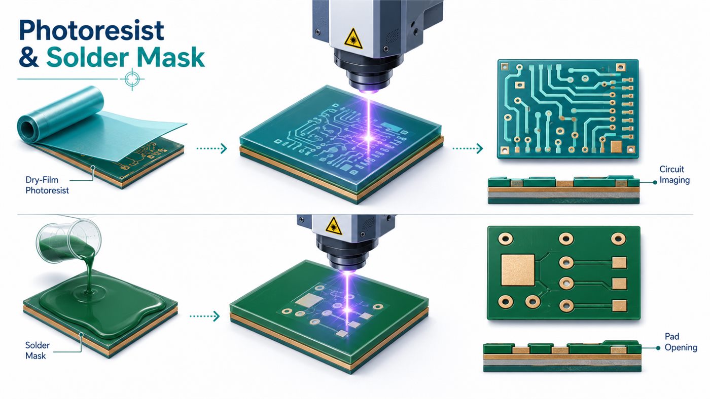
LDI exposure of dry-film photoresist for circuit imaging and liquid solder mask for pad openings

In a laser direct imaging solder mask process, the PCB is first coated with liquid photoimageable material and partially dried. The LDI system then aligns the digital solder mask pattern with the actual copper pads before exposure.

After developing, solder mask is removed from pads, holes, test points, and other required openings. LDI solder mask is particularly useful for:

  • Fine-pitch BGA pads
  • QFN and LGA footprints
  • Small solder mask dams
  • Dense connector pads
  • Closely spaced test points
  • Flexible circuits
  • Boards with tight mask-to-pad registration

Because the image is aligned to the real panel, the manufacturer may not need to enlarge solder mask openings as much as with less accurate exposure methods. This can help preserve narrow dams between adjacent pads.

LDI does not remove the need for realistic design rules. Final solder mask openings still depend on manufacturer registration tolerance, coating thickness, solder mask chemistry, development control, surface finish, assembly requirements, and solder mask color. White, black, and other less-transmissive colors may require different exposure settings, so critical dams and colors should be specified during quotation.

Laser Direct Imaging vs Traditional Photolithography

The choice depends on whether the PCB needs digital compensation, tighter registration, or phototool-free processing.
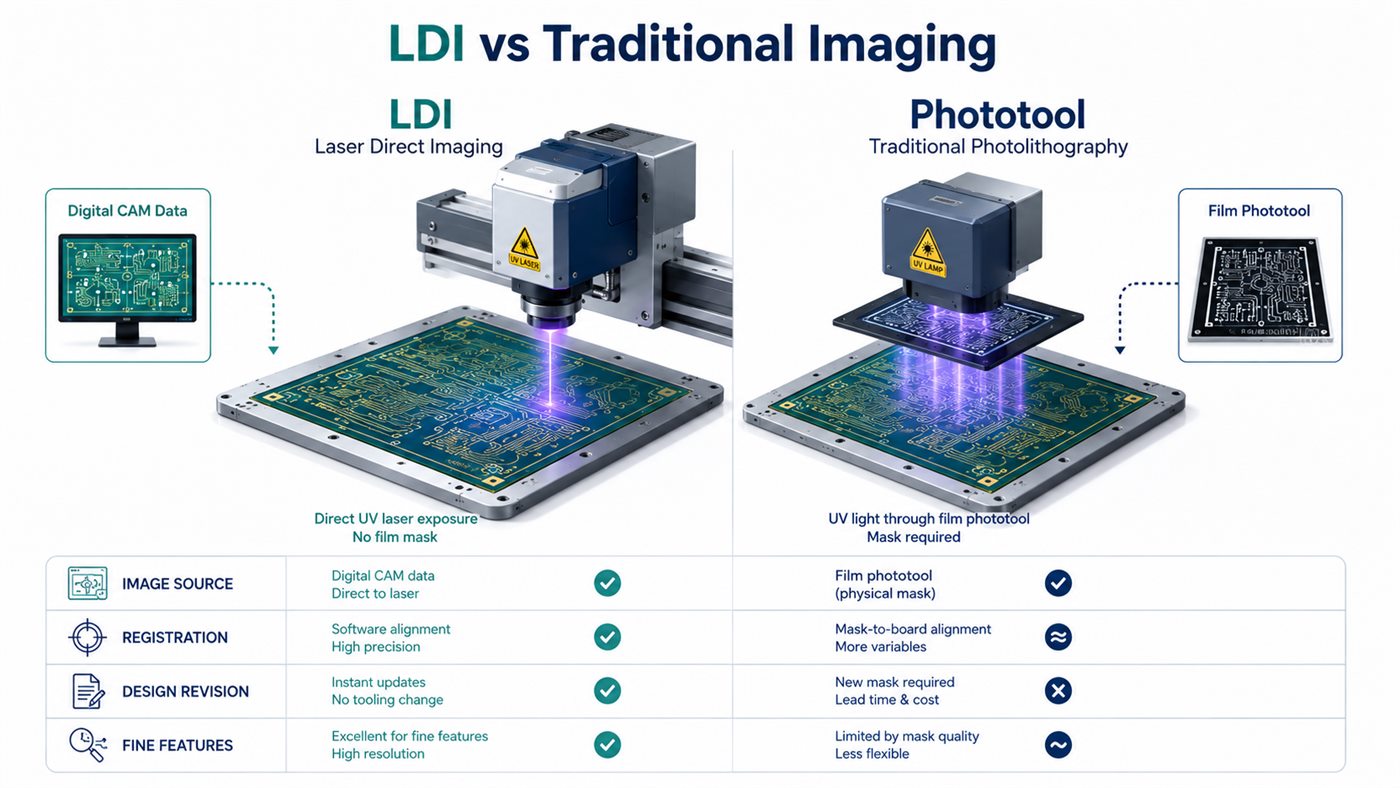
Comparison of laser direct imaging and traditional phototool PCB exposure
Comparison Point Laser Direct Imaging Traditional Photolithography
Image source Digital CAM data Film or glass phototool
Physical mask Not required Required
Registration Digitally corrected Depends on film and tooling
Panel distortion Can be compensated within process limits More difficult to correct
Design revisions CAM data can be updated New film may be required
Fine features Better suited to dense patterns Suitable for conventional geometry
Prototype setup No film preparation Additional phototool preparation
Flex materials Better compensation for dimensional movement More dependent on fixed scaling
Equipment investment Higher Usually lower
Simple volume boards May offer limited benefit Often practical and economical

Traditional imaging remains suitable when the board geometry is comfortably within the manufacturer’s process window. LDI becomes more valuable as trace, spacing, and registration margins become tighter.

What Are the Advantages of Laser Direct Imaging?

LDI provides practical benefits when imaging accuracy is a major manufacturing constraint:

  • More accurate registration: The exposure image can be matched to the measured panel.
  • Better fine-line support: Narrow traces, spaces, pads, and solder mask dams can be positioned more accurately.
  • Faster engineering revisions: Updated artwork does not require a new film set.
  • Fewer phototool defects: Film scratches, stretching, dust, and handling damage are removed from the process.
  • Material compensation: Digital scaling helps with thin cores, flex materials, and sequentially laminated structures.
  • Efficient prototype preparation: Small batches and revised designs can move into exposure without film production.
  • Improved solder mask alignment: Openings can follow the actual copper pattern rather than the nominal panel position.

These advantages matter most when conventional imaging is close to its practical limits. LDI will not compensate for weak stack-up design, excessive etching variation, or unrealistic PCB tolerances.

What Are the Limitations of Laser Direct Imaging?

LDI equipment requires high capital investment, controlled production conditions, regular calibration, preventive maintenance, and trained operators.

Other limitations include:

  • Exposure speed may drop with slow photoresist or dense image areas.
  • Photoresist and solder mask must match the machine wavelength.
  • Poor copper cleaning can still cause resist failure.
  • Warped panels may exceed the autofocus or handling range.
  • Uneven coating thickness can affect exposure results.
  • Severe panel distortion cannot always be corrected.
  • Fine imaging still depends on stable plating and etching.
  • Simple PCBs may not gain enough benefit to justify the process cost.

For a standard double-sided PCB with wide traces and generous clearances, conventional exposure may provide the same usable result at a lower cost.

Which PCB Types Benefit Most from LDI?
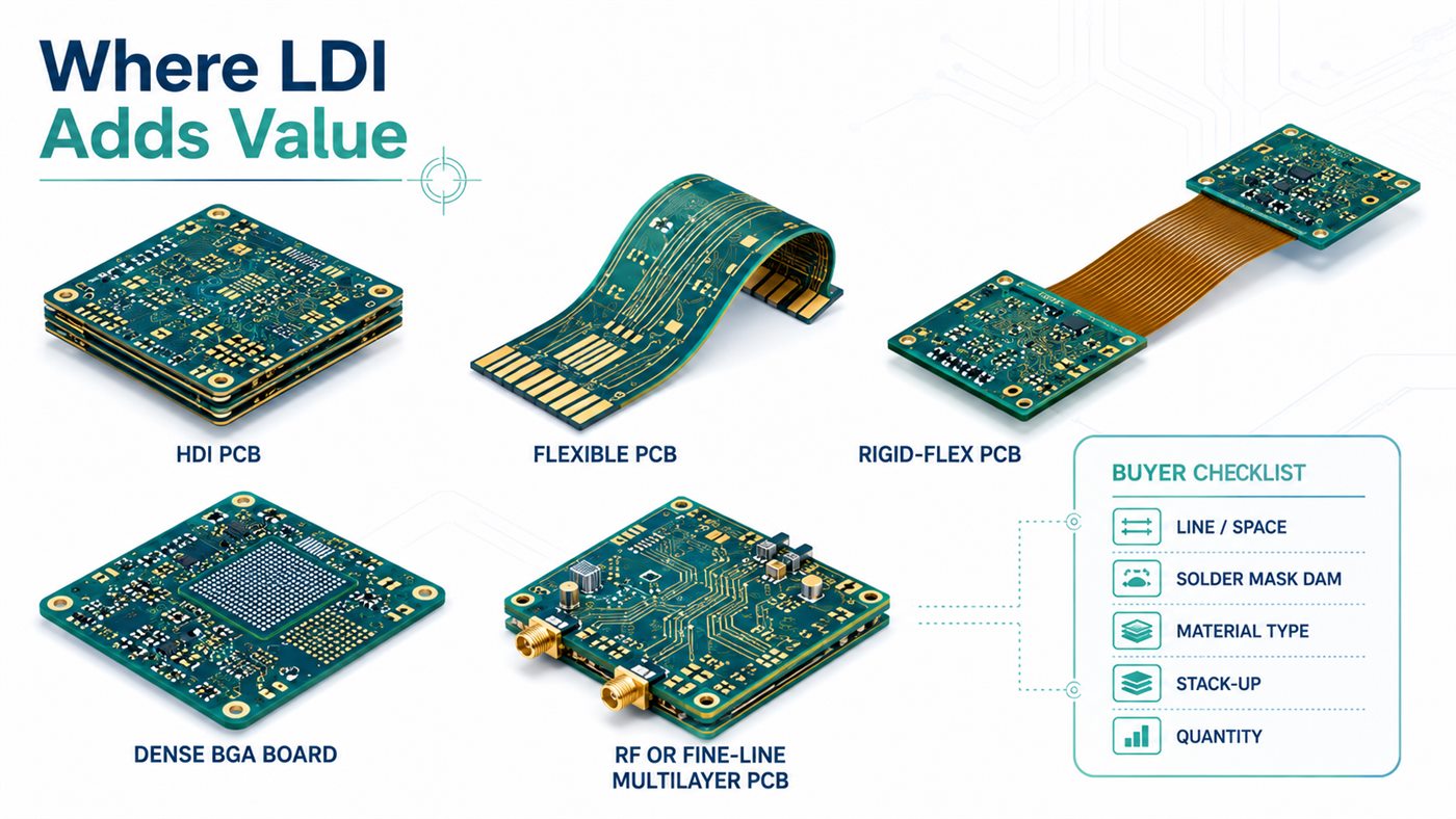
PCB types that benefit from LDI with buyer checklist for line space, solder mask dam, material, stack-up, and quantity

LDI provides the greatest value where feature density or material movement leaves little room for registration error.

PCB Type Why LDI Helps Main Imaging Concern
HDI PCB Supports dense build-up routing Fine lines and small microvia pads
Fine-line multilayer PCB Improves layer pattern placement Narrow traces and annular rings
Flexible PCB Compensates for material movement Stretching and shrinkage
Rigid-flex PCB Handles different material behavior Uneven dimensional change
BGA breakout board Supports dense fan-out routing Fine spacing and mask dams
RF or microwave PCB Preserves conductor geometry Line-width accuracy
Package substrate Supports very dense patterns Fine features and registration
Prototype PCB Simplifies design revisions Repeated artwork changes

A PCB does not need LDI simply because it has many layers. A high-layer-count board with conservative geometry may be easier to image than a thin four-layer flex PCB with tight solder mask registration.

When Should a PCB Design Require LDI?

LDI should be discussed when the design includes one or more of the following:

  • Trace and space near the manufacturer’s conventional imaging limit
  • Small annular rings
  • Dense BGA fan-out
  • Fine-pitch connector routing
  • Small solder mask dams
  • Tight solder mask-to-copper alignment
  • Thin flex materials
  • Sequential lamination
  • Tight layer-to-layer registration
  • Frequent prototype revisions

The design package should clearly state:

  • Minimum line width and spacing
  • Smallest annular ring
  • Finished copper thickness
  • Solder mask dam and color
  • Material type and stack-up
  • Impedance requirements
  • Quantity and lead time

These values allow the PCB manufacturer to decide whether LDI is necessary, beneficial, or unnecessary.

What Affects LDI PCB Cost, Lead Time, and Manufacturing Yield?

PCB buyers rarely need to know the purchase price of the LDI machine. Their project cost is influenced more directly by exposure time, materials, panel utilization, process complexity, and expected yield.

  • Trace and spacing: Features near the process limit require tighter control.
  • Layer count: Each additional circuit layer adds imaging and inspection steps.
  • Image density: Dense patterns may increase exposure time.
  • Photoresist speed: Slower materials reduce equipment throughput.
  • Solder mask detail: Small dams and tight openings require a narrower process window.
  • Material stability: Flex and thin-core materials may require more compensation.
  • Panel utilization: Poor nesting increases the cost per finished board.
  • Inspection requirements: Fine-line designs may require more detailed AOI review.
  • Yield risk: Designs combining several minimum features may require engineering trials.

LDI can shorten phototool preparation, but drilling, lamination, plating, surface finish, electrical testing, and material availability may have a greater effect on the final lead time.

How Should Buyers Evaluate a PCB Manufacturer’s LDI Capability?

Owning an LDI machine does not mean a supplier can produce every fine-line design reliably. Ask the manufacturer:

  • What minimum trace and space are stable in volume production?
  • Are the stated limits standard capability or prototype capability?
  • What registration tolerance can be maintained?
  • Is LDI used for inner layers, outer layers, solder mask, or all three?
  • Which dry-film and solder mask materials are qualified?
  • Can the process compensate for flexible-material movement?
  • What registration targets are required?
  • How are exposure focus and energy controlled?
  • What inspection follows the imaging process?
  • How is capability verified across the entire production panel?

For quotation, provide:

  • Gerber or ODB++ data
  • NC drill files
  • Fabrication drawing
  • Stack-up and material specification
  • Finished copper thickness
  • Impedance requirements
  • Solder mask color and minimum dam
  • Order quantity and delivery target

At EBest Circuit, we can review these details before quotation and determine whether LDI is required for the circuit pattern, solder mask, or both. This is more useful than requesting a specific equipment brand because the imaging method must match the complete PCB construction.

FAQs About Laser Direct Imaging

Q1. Is laser direct imaging the same as laser etching?

No. LDI exposes photosensitive material to form a pattern. Copper is removed later through chemical etching. Laser etching removes or changes material directly.

Q2. Does LDI remove copper from a PCB?

No. It defines the photoresist image. Etching or plating takes place in a later manufacturing step.

Q3. Can LDI be used for flexible PCBs?

Yes. Digital image compensation is useful for thin flexible materials that may expand, shrink, or distort during production.

Q4. Can LDI expose both dry film and liquid solder mask?

Yes, as long as the material is compatible with the machine wavelength and exposure energy.

Q5. What wavelength is used for PCB laser direct imaging?

Common systems use ultraviolet wavelengths such as 355 nm or 405 nm. Multi-wavelength equipment is also available.

Q6. Does every HDI PCB require LDI?

No. Some HDI boards can be produced with conventional exposure when their traces, spacing, annular rings, and registration tolerances remain within a stable process window.

Q7. Is LDI faster than traditional photolithography?

It removes film preparation, but exposure throughput depends on the machine, image density, panel area, resist sensitivity, and alignment method.

Q8. Does LDI improve PCB manufacturing yield?

It can improve yield when registration error or panel movement is a major defect source. Yield also depends on lamination, plating, development, etching, and inspection.

Q9. Can LDI compensate for panel expansion and shrinkage?

Yes, within the correction range of the equipment. Severe or irregular distortion may still make the panel unusable.

Q10. What files are required for LDI imaging?

The manufacturer normally needs Gerber or ODB++ data, drill files, a fabrication drawing, and stack-up information.

Q11. Is LDI suitable for prototype and volume production?

Yes. It supports fast artwork revisions for prototypes and is also used in volume production of HDI, multilayer, flex, and substrate products.

Q12. What is the difference between LDI and laser drilling?

LDI exposes photosensitive material. Laser drilling removes dielectric material to create microvias. They are separate PCB manufacturing processes.

Laser direct imaging is most useful when fine features, material movement, or registration requirements are difficult to control with conventional phototools. It can improve circuit imaging, solder mask alignment, and prototype revision efficiency, but it does not replace sound design rules or stable downstream processing.

For a manufacturing review, send your Gerber files, stack-up, quantity, minimum line and space, solder mask requirements, and delivery target to sales@bestpcbs.com. We can evaluate whether LDI is technically necessary and recommend a practical production route.

You may also like

What is laser direct imaging(LDI) in PCB manufacturing?
Thursday, February 13th, 2025

Laser direct imaging (LDI) is an advanced PCB manufacturing technology that uses a computer-controlled laser beam to directly expose circuit patterns on a PCB substrate coated with photosensitive material. This technology can achieve high-precision imaging effects and significantly improve production efficiency and imaging quality.

What is laser direct imaging?

Laser Direct Imaging (LDI) is an advanced PCB manufacturing technique that directly transfers circuit patterns onto a photoresist-coated board using laser technology.

What is laser direct imaging(LDI) in PCB manufacturing?

Unlike traditional photolithography, which relies on photomasks, LDI uses computer-controlled lasers to etch intricate designs with extreme precision.

This method significantly enhances accuracy, speed, and flexibility, making it a preferred choice for modern PCB production, especially for high-density interconnect (HDI) boards.

How does LDI differ from traditional imaging?

Traditional PCB imaging depends on photomasks to transfer circuit designs onto the PCB. This process involves multiple steps, including photomask fabrication, manual alignment, and exposure to UV light.

Since photomasks are physical templates, they can degrade over time, leading to inconsistencies in production.

LDI eliminates these challenges by using digital laser beams to expose the photoresist layer directly, ensuring greater precision and efficiency. Here’s how LDI stands out:

  • No photomasks required – Eliminates costs and maintenance associated with masks.
  • Higher precision – Laser beams can achieve much finer line widths than traditional methods.
  • Fast design modifications – Digital files allow for easy and quick adjustments.
  • Less material waste – Reduces the need for physical stencils, making the process eco-friendly.

Why is LDI important for PCB manufacturing?

The demand for compact, high-performance electronics continues to grow. LDI technology plays a crucial role in meeting these demands by allowing manufacturers to create complex circuit layouts with extreme accuracy.

What is laser direct imaging(LDI) in PCB manufacturing?

Key Benefits of LDI in PCB Production:

  • Fine-line circuit imaging – Supports line widths as small as 50 microns or less.
  • Better alignment precision – Perfect for multilayer PCBs where layers must align perfectly.
  • Faster turnaround time – Since no photomasks are required, production cycles are shorter.
  • Cost-effective for prototypes – Ideal for low to medium-volume production runs.
  • Reduces defects – Eliminates common photolithography issues like misalignment and dust contamination.

What is LDI used for in PCB manufacturing?

LDI is especially valuable for:

  • HDI PCBs – Enables the creation of extremely fine pitch traces.
  • Flexible & Rigid-Flex PCBs – Ensures precise patterning for flexible circuits.
  • Prototyping & Small Batch Production – Reduces the need for costly photomask production.

What are the steps in the laser imaging process?

The LDI process follows a precise workflow to ensure accurate circuit patterning on the PCB. Here’s how it works:

  • Pre-Processing & Design Preparation – The PCB layout is converted into a digital file for LDI processing.
  • Photoresist Application – The PCB is coated with a light-sensitive photoresist layer.
  • Laser Exposure – High-precision UV lasers expose the design directly onto the photoresist.
  • Development Process – Unexposed photoresist is removed, revealing the circuit pattern.
  • Etching & Stripping – Unwanted copper is etched away, leaving the final circuit traces.
  • Quality Inspection – The board undergoes optical and electrical testing to ensure precision.

How does laser direct imaging work?

LDI uses a high-intensity laser beam to directly expose the photoresist layer on the PCB without needing a photomask. The system moves the laser precisely across the board, creating circuit traces based on a digitally stored layout.

What is laser direct imaging(LDI) in PCB manufacturing?

Since the laser operates with pinpoint accuracy, it ensures perfect pattern alignment, making it especially useful for HDI and multilayer PCB manufacturing.

What are the advantages of laser direct imaging?

LDI has transformed the PCB manufacturing industry with its unmatched speed, accuracy, and efficiency.

1. Enhanced Precision

  • Allows for narrow trace widths and tight spacing.
  • Reduces alignment errors in multilayer PCBs.
  • Supports the production of high-density circuit boards.

2. Eliminates Photomasks

  • No need to create, store, or maintain expensive photomasks.
  • Digital files can be easily modified for design updates.

3. Faster Production Cycles

What is laser direct imaging(LDI) in PCB manufacturing?
  • Reduces imaging time compared to traditional methods.
  • Supports rapid prototyping and quick design changes.

4. Cost-Efficiency for Prototyping & Low-Volume Runs

  • Ideal for custom PCB designs and small-batch production.
  • Avoids high costs associated with mask creation.

5. Consistent & Reliable Results

  • No photomask degradation means every board is identical.
  • Reduces defects like overexposure, misalignment, and contamination.

What are the disadvantages of laser direct imaging?

Despite its benefits, LDI is not without challenges. Here are some considerations:

  • 1. High Initial Investment: LDI equipment is more expensive than traditional imaging tools.
  • 2. Higher Power Consumption: Laser systems require significant energy to operate efficiently.
  • 3. Not Always Ideal for High-Volume Production: For very large-scale manufacturing, traditional photolithography may still be more cost-effective.
Conclusion:

Laser Direct Imaging has revolutionized PCB manufacturing, offering higher accuracy, efficiency, and flexibility compared to traditional imaging techniques.

If you need precision-engineered PCBs with LDI technology, EBest Circuit (Best Technology) is your trusted partner. Contact us at: sales@bestpcbs.com

You may also like

What is Laser Direct Imaging in PCB Manufacturing?
Wednesday, October 30th, 2024

‌What is Laser Direct Imaging?

Laser Direct Imaging (LDI) is a technology that uses a laser beam emitted by an ultraviolet laser to image directly on a PCB (printed circuit board). Compared to traditional exposure techniques, LDI has higher image quality, precision traces and real-time adjustment.

The LDI technology achieves pattern transfer by projecting the line image directly onto the PCB coated with photoresist through the laser beam emitted by the laser diode. This method eliminates the use of negatives in the traditional exposure process, reduces the time and cost of loading and unloading negatives, and avoids deviations caused by negative growing. The image resolution of LDI technology is high, and the fine wire can reach about 20um, which is suitable for the production of fine wire and improves the yield of PCB production.

What is Laser Direct Imaging in PCB Manufacturing?

Working Principle of LDI Technology

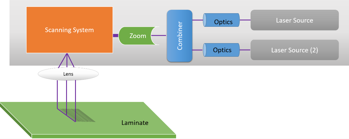
The principle of laser imaging is to acquire and present images based on the characteristics of laser beam. As we know, a laser is a highly focused, high-brightness, monochromatic beam that can therefore produce high-quality images. The laser imaging system mainly consists of laser, lens, scanning device and receiver. The laser is used to generate the laser beam, the lens is used to focus the beam, the scanning device is used to change the path of the beam on the object, and the receiver is used to receive the light signal and convert it into an image.

In the imaging process, the laser beam is focused from the laser through the lens, and then the path of the beam on the object is controlled by the scanning device. When the laser beam hits the surface of an object, it interacts with the surface. This interaction causes light to scatter and reflect, with scattered light diffusing in different directions and reflected light remaining in its original direction of propagation. The receiver receives the light scattered and reflected by the object and converts it into an electrical signal. The receiver converts the signal into a digital image signal, which is then processed and displayed on the screen to form an image. In the processing process, the received signal can be filtered, amplified and other operations to improve the quality and clarity of the image.

What is Laser Direct Imaging in PCB Manufacturing?

As PCB manufacturing processes continue to advance, LDI technology is also evolving. At present, the mainstream light source in the industry is the 405nm laser diode produced by Nichiya, Panasonic, and it is expected that the optical power requirements for exposure will be further improved in the future, and the optical power of a single device may develop to 100W. Nowadays, LDI technology is not only used in PCB manufacturing process, but also in high-end applications like medical imaging, industrial detection, remote sensing.

Advantages of Laser Direct Imaging Over Photo Exposure

The advantages of laser direct imaging (LDI) compared with traditional exposure machines mainly include the following aspects:

1. Eliminating the negative process in the exposure process

    The LDI technology eliminates the step of making the negative in the traditional exposure process, thereby saving the time and cost of loading and unloading the negative, and reducing the deviation caused by the negative growth and contraction.

    2. High resolution

    The image resolution of LDI technology is very high, which is suitable for some very fine line production, especially for multi-layer PCB, which greatly improves the yield of PCB production.

    3. High quality and precision

    LDI is contactless operation, reducing the chance of miscontact, the closed operating environment reduces the influence of temperature and humidity, the image quality is high and fine, eliminating many defects in the traditional process.

    4. Reduce errors and improve alignment

    LDI technology improves alignment by eliminating alignment problems that often exist in photographic plates, especially the anisotropic movement of photographic plates caused by changes in temperature and humidity. High-precision alignment is achieved by using a charge-coupled device (CCD) camera system and a reference target to line up printed images and panels.

    5. Shorten the production process and reduce costs

    Because there is no need to have a negative production process, LDI technology shortens the production process, reduces the call of personnel, and reduces the production cost. In addition, the LDI system can lay more devices in the same environment, enabling two-way scanning and further savings.

    6. Adapt to a variety of production needs

    LDI technology has a flexible manufacturing route, which can meet various production needs without affecting the output. Once the data is delivered to the engineering department, production can begin, reducing product delivery time.

    The image quality of LDI technology is clearer than that of traditional exposure technology, and it has obvious advantages in mid-to-high-end PCB manufacturing. With the transfer of global PCB production capacity to China and the high-end development of the electronics industry, the demand for LDI equipment continues to grow, and it is expected that the future will gradually replace traditional exposure equipment in the field of low-end PCB.

    What is the Process of Direct Imaging?

    Direct imaging with LDI involves several steps that ensure precise layer creation:

    • Design Preparation: The digital circuit design is prepped for imaging, with adjustments made to accommodate laser processing specifics.
    • Photoresist Coating: The PCB is coated with a light-sensitive photoresist material, which reacts chemically when exposed to the laser.
    • Laser Imaging: The laser projects the circuit pattern directly onto the photoresist. Adjustments can be made mid-process, allowing for precise alignment.
    • Developing: After exposure, the board is treated with a developer to reveal the circuit paths. Unexposed areas are removed, leaving only the intended design.
    • Etching or Plating: Depending on the PCB type, the board undergoes etching or plating to define the copper traces, completing the imaging process.

    Difference Between Positive and Negative Images in PCB

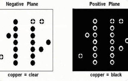
    In PCB photo exposure, the terms “positive” and “negative” refer to how the photoresist reacts to the laser exposure:

    • Positive Image: Here, the laser exposes areas intended to be removed. During development, the exposed regions dissolve, leaving behind the unexposed areas as the design.
    • Negative Image: In a negative image process, the laser exposes the regions meant to remain on the board. These exposed parts resist the developer, protecting the underlying material, while unexposed regions dissolve away.
    What is Laser Direct Imaging in PCB Manufacturing?

    The choice between positive and negative imaging depends on the photoresist type and the specific design requirements. Both methods offer high accuracy, but each has unique benefits based on the intended application.

    Why LDI Process Less Cost-effective than Phototool?

    While LDI offers many advantages, it often requires a higher initial investment than phototools:

    1. Equipment Costs: LDI machines are sophisticated and costly, requiring a significant investment in laser technology and imaging systems.

    2. Maintenance: High-precision lasers and optics demand regular maintenance and calibration to ensure consistent performance, which adds to operational costs.

    3. Speed on Larger Runs: For high-volume production, phototools may still be more cost-effective. Phototools offer rapid replication without the need for repeated laser exposure, lowering costs for large-scale production.

    These cost factors make LDI more suitable for specialized, lower-volume, or high-precision applications rather than large-batch productions.

    How is Layer Registration in LDI?

    Layer registration is crucial in PCB manufacturing, especially for multilayer boards where each layer must align precisely. LDI excels in this aspect:

    1. Automated Alignment: LDI systems come with advanced alignment software that adjusts each laser exposure to match the existing layer positions.

    2. Reduced Human Error: Since the process is largely automated, human handling is minimal, reducing the risk of alignment issues.

    3. Dynamic Adjustment: With real-time feedback systems, LDI machines adjust alignment during the process, maintaining tight registration tolerances.

    If you’re seeking high-quality PCB manufacturing, consider choosing a provider skilled in LDI processes like EBest Circuit (Best Technology). Our company combines expertise with cutting-edge technology to ensure your boards are produced to exact specifications, delivering the durability and performance you need in today’s advanced electronics.

    You may also like

    What is laser direct imaging technology?
    Wednesday, October 9th, 2024

    Laser direct imaging (LDI) technology is a process that uses lasers to expose images directly on photoresists, mainly used in the exposure process of PCB manufacturing processes. LDI is a widely used technology that can create a variety of images and is used in various industries, including electronics, automotive and medical industries.

    What is laser direct imaging?

    Laser direct imaging (LDI) is an advanced photolithography technology. It directly uses a laser beam to expose images on photoresists, eliminating the intermediate step of making photolithography masks in traditional photolithography technology.

    What is laser direct imaging technology?

    In this process, the laser beam is precisely controlled according to the pre-set circuit pattern data. The laser emitted by the laser light source is processed by a series of optical components, such as beam expansion and focusing, and then the laser beam is guided by the scanning system to scan and expose the surface of the printed circuit board (PCB) coated with photoresist.

    The photoresist responds to the laser energy, and according to the type of photoresist (positive or negative), the corresponding chemical changes occur in the laser irradiation area. This change will lay the foundation for subsequent development and other processes, thereby forming an accurate circuit pattern.

    What is the principle of laser direct imaging?

    The principle of laser direct imaging (LDI) is to expose the pattern directly on the substrate coated with photosensitive material through a computer-controlled laser beam.

    Specifically, the workflow of LDI includes the following steps: First, the designed circuit pattern is converted into the image generation program of the spatial light modulator through computer-aided manufacturing (CAM) software. Then, the laser beam passes through the spatial light modulator, and the generated image is projected onto the substrate coated with photosensitive material through the optical imaging system to complete the pattern exposure. Compared with the traditional mask exposure process, LDI saves the film process in the exposure process and greatly improves the production efficiency.

    The main advantages of LDI technology are its efficiency and precision. It directly uses a highly focused laser beam controlled by a computer to define the circuit pattern on the PCB copper layer covered with laser photoresist without the need for photographic tools, thus avoiding the film and printing defects in the traditional process.

    In addition, LDI also optimizes the production environment, eliminates the influence of temperature and humidity on the product, and further improves the production quality and efficiency.

    How does laser direct imaging (LDI) work?

    Laser direct imaging (LDI) technology is a process that uses laser to directly expose and image on photoresist, and is mainly used in the exposure process in the PCB manufacturing process. Its working principle is as follows:

    • 1. Design graphics: Design the circuit graphics to be produced through computer-aided design (CAD) software.
    What is laser direct imaging technology?
    • 2. Generate images: Convert the designed circuit graphics into digital images and transmit them to the control system of the LDI equipment.
    • 3. Laser scanning: The laser beam in the LDI equipment scans and exposes the photoresist according to the information of the digital image under the precise control of the control system.
    • 4. Photochemical reaction: The photoresist undergoes a photochemical reaction under the irradiation of the laser, changing its solubility.
    • 5. Development: The exposed photoresist is developed in the developer to remove the unexposed part of the photoresist, thereby forming a circuit pattern on the photoresist that is consistent with the design graphics.
    • 6. Etching or electroplating: According to needs, the developed circuit board is etched or electroplated and other subsequent processes are performed to produce the actual circuit.

    Compared with traditional exposure technology, LDI technology has higher resolution and precision, can produce finer circuit wiring and smaller line spacing, and also has higher production efficiency and flexibility.

    What are the advantages of using laser direct imaging?

    The main advantages of LDI (Laser Direct Image) technology include: eliminating the film process in the exposure process, saving time and cost for loading and unloading films, and reducing deviations caused by film expansion and contraction; directly imaging CAM data on PCB, eliminating CAM production process; high image resolution, fine wires can reach about 20um, suitable for fine wire production; improve PCB production yield.

    The main problems of LDI technology include: high-precision lasers and optical systems are required, which increases the cost and complexity of the equipment; high environmental requirements, temperature and humidity need to be controlled to ensure imaging quality; high technical requirements for operators, and professional training is required to operate the equipment proficiently.

    The advantages of LDI technology in the flexible board industry include: improving production efficiency, no need to make and replace physical masks, shortening production cycles and waiting time; high-precision imaging, capable of processing finer and more complex graphics, improving product yield and reliability; efficient use of materials, reducing material waste; environmental advantages, reducing the use of chemicals, and reducing environmental pollution.

    What are the disadvantages of laser direct imaging?

    The disadvantages of laser direct imaging (LDI) technology mainly include:

    • 1. High equipment cost: LDI equipment is usually expensive and requires a large initial investment, which may be a burden for some small enterprises or projects.
    What is laser direct imaging technology?
    • 2. High environmental requirements: LDI equipment needs to work in a specific environment, such as a dark room or a low-illuminance red light environment, which increases the requirements for the working environment.
    • 3. Technical complexity: LDI technology involves multiple steps and complex process flows, with high technical requirements for operators, and long training costs and time.
    • 4. High material cost: LDI requires the use of specific photoresists and laser diodes, which are expensive and increase production costs.
    • 5. Speckle problem: After the laser beam is reflected or transmitted through a rough surface, it will form countless independent scattered sub-waves. These sub-waves are coherently superimposed during the spatial propagation process, forming random and irregularly distributed bright and dark spots in space, that is, speckle phenomenon, which may affect the imaging quality.

    In summary, although LDI technology has the advantages of high precision and high efficiency, its disadvantages such as high equipment cost, complex technical requirements and speckle problem also need to be considered when using it.

    When is laser direct imaging used?

    Laser direct imaging LDI is mainly used in the exposure process in PCB manufacturing, especially when high precision and efficient production are required. This technology is particularly suitable for the production of fine-line and ultra-fine-line circuit boards, and can achieve the best imaging effect.

    In addition, LDI technology is also widely used in the field of FPC soft boards, which can improve production efficiency and product quality, and support complex circuit structures and high-density layouts.

    The advantages of laser direct imaging LDI technology include:

    • 1. High precision: It can achieve high-resolution pattern exposure and improve product performance and reliability.
    • 2. Efficient production: shorten the exposure process, speed up production and reduce costs.
    • 3. Complex circuit structure: support the exposure of multi-layer FPC and meet the needs of high-density layout.

    Laser direct imaging technology is a highly promising technology in the field of PCB manufacturing. It has many advantages in terms of precision, flexibility, production efficiency and cost-effectiveness, and plays an important role in PCB manufacturing in many fields such as high-end electronic products, automotive electronics, industrial control and communication equipment.

    You may also like