PCB manufacturing PCB manufacturing
Home > Blog

aluminum pcb vs fr4

Aluminum PCB Circuit Board Complete Guide
Thursday, May 14th, 2026

What Is an Aluminum PCB?

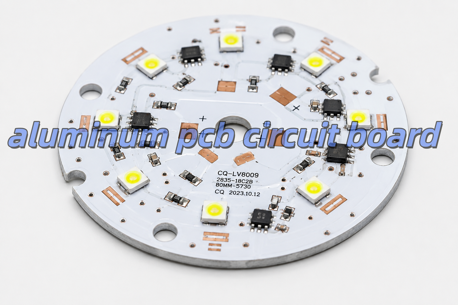
An aluminum PCB is a printed circuit board with an aluminum metal base. It is also called an aluminum core PCB, metal core PCB, or MCPCB. Its main purpose is to move heat away from components.
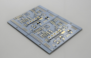
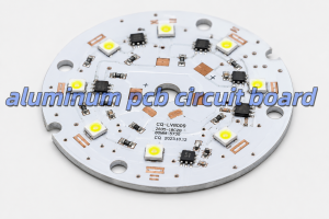
aluminum pcb circuit board

A normal FR4 PCB uses fiberglass as the base material. However, an aluminum PCB uses a metal base. Because aluminum transfers heat better than FR4, It helps reduce heat accumulation around high-temperature components.

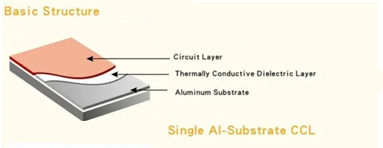
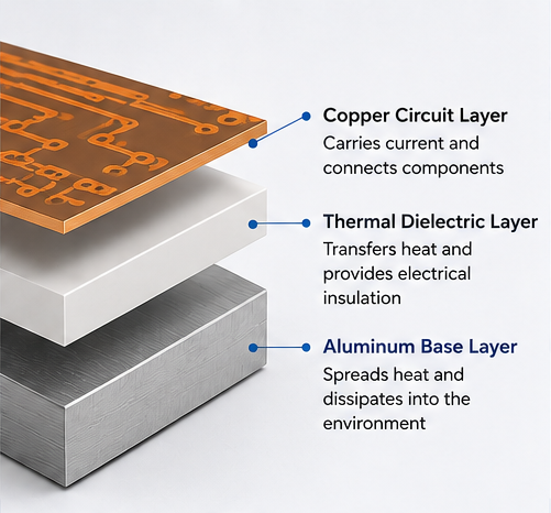
Typical aluminum-based printed circuit board has three main layers,as following:

LayerMain JobWhy It Matters
Copper Circuit LayerCarries current and signalsHelps the circuit work
Thermal Dielectric LayerMoves heat and insulates electricityControls heat and safety
Aluminum Base LayerSpreads heatKeeps the board cooler

The copper layer forms the circuit. The dielectric layer moves heat downward. Then, the aluminum base spreads the heat into the housing, air, or heat sink.

Because of this structure, aluminum PCB is a strong choice for LED lights, power boards, and other heat-sensitive products.

How Does an Aluminum PCB Circuit Board Dissipate Heat?

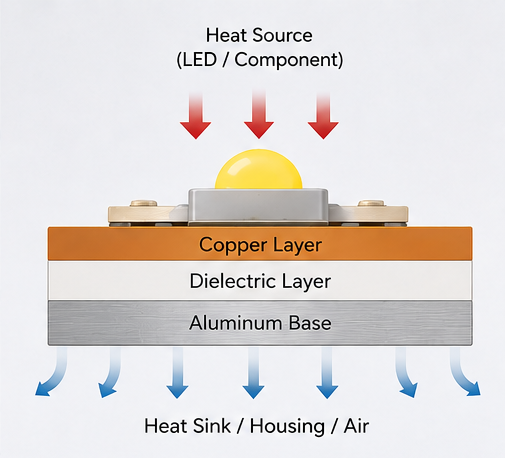
An aluminum PCB circuit board dissipates heat through a short heat path. First, heat starts at the component. Then, it moves into the solder joint and copper layer. After that, it passes through the dielectric layer. Finally, it reaches the aluminum base.

The heat path is usually:

Component → Solder Joint → Copper Layer → Dielectric Layer → Aluminum Base → Heat Sink
Heat dissipation path

The dielectric layer is very important. It must move heat well. However, it must also keep electricity away from the aluminum base.

If this layer is poor, the board may still run hot. Therefore, the material quality matters. It is not enough to choose a board only because it has an aluminum base.

Also, the whole product design affects heat. For example, copper area, pad size, airflow, housing contact, and heat sink design all play a role. Therefore, the PCB should be reviewed together with the full product structure.

What Materials Are Used in Aluminum PCBs?

The aluminum PCB is made from copper foil, thermal dielectric material, aluminum base, solder mask, and surface finish. Each material affects heat control, electrical safety, soldering quality, and service life.

Copper Circuit Layer

The copper layer carries current. Also, it helps spread heat from component pads.

Copper ThicknessCommon Use
1 ozStandard LED lighting and simple circuits
2 ozHigher-current LED and power boards
3 oz or aboveHeavy-current power designs

For simple LED boards, 1 oz copper is often enough. However, for automotive lamps, power boards, and industrial modules, 2 oz copper may be better.

Thicker copper can carry more current. It can also reduce heat rise. However, it may increase production cost.

Thermal Dielectric Layer

The dielectric layer sits between the copper and the aluminum base. It has two jobs. First, it moves heat. Second, it provides electrical insulation.

Important points include:

  • Heat transfer
  • Insulation strength
  • Thickness
  • Heat resistance
  • Bonding strength
  • Long-term stability

A thinner dielectric layer can move heat faster. However, it must still meet the voltage and safety needs of the product.

Aluminum Base Layer

The aluminum base gives the PCB strength. It also spreads heat away from hot parts.

Aluminum ThicknessCommon Use
0.8 mmLight LED modules
1.0 mmGeneral lighting products
1.5 mmCommon aluminum PCB design
2.0 mm or aboveHigh-power or rugged products

For many LED boards, 1.5 mm is a common choice. However, larger lamps and industrial products may need 2.0 mm or thicker aluminum.

Solder Mask and Surface Finish

White solder mask is common for LED aluminum PCB. It reflects light better than dark solder mask. As a result, it helps improve light output.

Common surface finishes include lead-free HASL, ENIG, OSP, and immersion silver. For example, lead-free HASL is often used for standard LED boards. However, ENIG is better when the board needs a flat surface or fine-pitch parts.
aluminum-pcb-layer-structure

What Are the Common Aluminum PCB Stackup Types?

The most common aluminum PCB is single-sided. However, double-sided and hybrid aluminum PCBs are also used. The right choice depends on heat, current, routing space, and cost.

Single-Sided Aluminum PCB

Single-sided aluminum PCB is the most popular type. The circuit and parts are on one side. The aluminum base is on the other side.It is often used in:

  • LED bulbs
  • Street lights
  • High-bay lights
  • Panel lights
  • Power modules
  • Simple driver boards

Also, this type is cost-effective. It gives heat a short path to the aluminum base.

Double-Sided Aluminum PCB

Double-sided aluminum PCB has circuits on both sides. It gives more space for routing. Therefore, it is useful when the circuit is more complex.

However, it is harder to produce than a single-sided board. The via structure and insulation must be controlled well.

Hybrid Aluminum PCB

Hybrid aluminum PCB combines FR4 layers with an aluminum base. It is useful when a product needs both signal routing and heat control.

For example, FR4 can handle control signals. Meanwhile, aluminum can help remove heat from the power section.

What Thermal Conductivity Should You Choose for Aluminum PCB?

The right thermal conductivity depends on the product. For many LED products, 1.0–1.5 W/m·K is enough. However, high-power products often need 2.0 W/m·K or more.

Thermal ConductivitySuitable UseSimple Advice
1.0 W/m·KLow-power LED productsGood for simple lighting
1.5 W/m·KStandard LED lightingCommon choice
2.0 W/m·KMedium-power LED and power boardsBetter for more heat
3.0 W/m·K or higherHigh-power LED, automotive, industrial boardsGood for demanding designs

Higher thermal conductivity can move heat faster. However, it is not the only factor. Copper thickness, dielectric thickness, pad design, and heat sink contact also matter.

Therefore, do not choose material only by price. Also, do not choose the highest value without checking the real heat load.

For sealed lamps, automotive lights, medical devices, and industrial modules, it is better to leave more safety margin. As a result, the product can work more safely over time.

How Should You Design an Aluminum PCB Circuit Board Layout?

A good aluminum PCB layout should control heat, current, insulation, and mounting. The board is not only a circuit carrier. It is also part of the heat system.

Place Hot Parts Properly

High-power LEDs, MOSFETs, regulators, drivers, and power resistors should not be packed into one small area.

If hot parts are too close, hot spots may appear. As a result, some parts may age faster.

Therefore, spread hot parts when the circuit allows it. This helps the aluminum base spread heat more evenly.

Use Wider Copper for High Current

High-current traces should not be too narrow. Narrow copper creates more resistance. As a result, it creates more heat.

For high-current areas, use:

  • Wider traces
  • Copper pours
  • Thicker copper
  • Shorter current paths
  • Better thermal pads

Also, copper balance is important in LED arrays. Uneven copper may affect heat flow and soldering quality.

Design Thermal Pads Well

Thermal pads help move heat from components into the PCB. For LEDs and power parts, the pad should be large enough.

Also, the pad should connect well to the copper area. As a result, the LED junction temperature can be lower.

Control Clearance and Creepage

The aluminum base is conductive. Therefore, insulation design is very important.

Check these areas:

  • High-voltage spacing
  • Board edge clearance
  • Mounting hole isolation
  • Connector spacing
  • Exposed aluminum areas
  • Screw contact points

This is very important for LED drivers, medical power boards, industrial power supplies, and automotive electronics.

Design Mounting Holes Carefully

Mounting holes affect both strength and safety. If screws touch the aluminum base, the design must confirm whether the base is grounded or isolated.

In many products, screws press the PCB against a heat sink. This helps heat transfer. However, the structure must not damage the insulation layer.

What Are the Advantages and Disadvantages of Aluminum PCBs?

Aluminum PCBs offer strong heat control and good strength. However, they also have some limits. For example, they cost more than basic FR4 boards. Also, they are not ideal for very dense multilayer routing.

ItemAdvantagesLimits
Heat ControlGood for LED and power productsDepends on dielectric quality
StrengthRigid and stableNot flexible
CostGood value for heat productsHigher than standard FR4
DesignGood for simple power circuitsHarder for dense routing
ReliabilityReduces heat stressNeeds correct material choice
ReworkStable after assemblyRework may be harder

The main benefit is heat control. If heat affects your product, aluminum PCB is often a good choice.

However, the board must match the real use. A high-power street light should not use the same material as a small decorative lamp. Therefore, material selection should be based on heat load, current, and working environment.

What Are Aluminum PCBs Used For?

Aluminum PCBs are used in products that need fast and stable heat transfer. They are common in LED lighting, power electronics, automotive electronics, industrial equipment, medical devices, and aerospace systems.

LED Lighting

LED lighting is one of the largest markets for aluminum PCB.Common products include:

  • LED bulbs
  • LED tubes
  • Street lights
  • High-bay lights
  • Stage lights
  • UV LED modules
  • Panel lights
  • Automotive LED lamps

In LED products, aluminum PCB helps control heat near the LED chip. As a result, it supports stable brightness and longer life.

Power Electronics

Power electronics often create high heat in small spaces. Therefore, aluminum PCB can help reduce heat build-up.

Typical products include power supplies, DC-DC converters, motor drivers, inverters, voltage regulator modules, and charging modules.

Automotive Electronics

Automotive electronics must work under heat, vibration, and long use.

Aluminum PCBs are often used in LED headlights, taillights, signal lights, interior lighting, power modules, and battery-related boards.

Industrial Equipment

Industrial products often run for long hours. Therefore, stable heat control is important.

Aluminum PCBs can be used in automation equipment, industrial LED indicators, power modules, control cabinets, motor control boards, and machine vision lighting.

Medical and Aerospace Electronics

Medical and aerospace products often need stable heat behavior and strong process control.

Aluminum PCB may be used in medical lighting, diagnostic modules, UAV electronics, aerospace lighting, and compact power boards.

In these fields, traceability, inspection records, and stable quality are also important.

Why Are Aluminum PCBs Popular in LED Lighting?
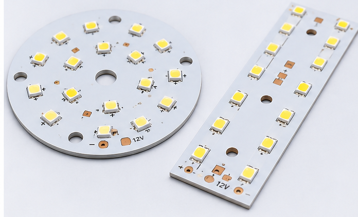
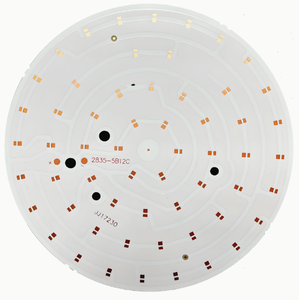
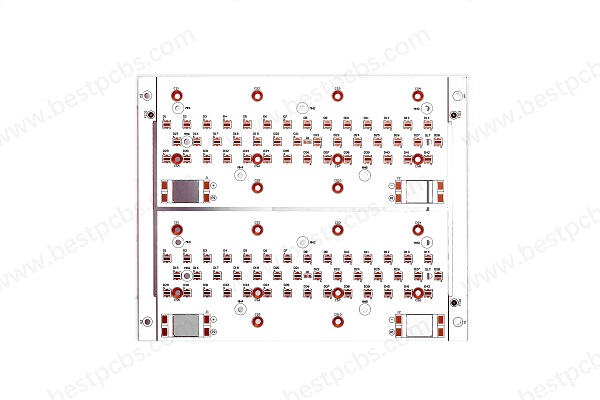
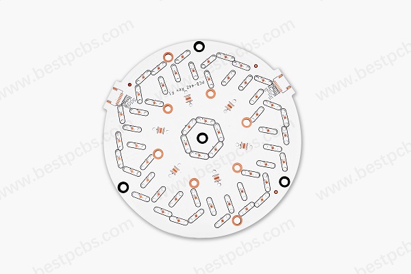
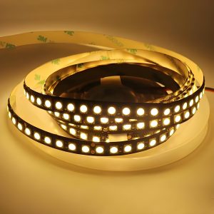
led-aluminum-pcb

Aluminum PCBs are popular in LED lighting because LEDs create heat during use. If the heat is not removed well, brightness and life may drop.

An LED does not turn all electric energy into light. Some energy becomes heat. If this heat stays near the LED chip, the junction temperature rises.

High junction temperature may cause:

  • Lower light output
  • Faster lumen loss
  • Color shift
  • Shorter service life
  • More solder joint stress

Therefore, aluminum PCB is a strong choice for LED lighting. It creates a shorter heat path from the LED package to the lamp housing or heat sink.

Design ItemCommon Choice
Board TypeSingle-sided aluminum PCB
Board Thickness1.5 mm
Copper Thickness1 oz or 2 oz
Solder MaskWhite
Surface FinishLead-free HASL or ENIG
Thermal Conductivity1.5–2.0 W/m·K

White solder mask is common in LED aluminum PCB. It reflects light better than dark solder mask. Therefore, it supports both heat control and light output.

For high-power street lights, industrial lights, and automotive lamps, higher thermal conductivity and thicker copper may be needed.

Aluminum PCB Circuit Board vs FR4 PCB: Which Is Better?

Aluminum PCB is better for heat control. However, FR4 PCB is better for complex routing and low-heat circuits. Therefore, the better choice depends on your design goal.

Comparison ItemAluminum PCB Circuit BoardFR4 PCB
Base MaterialAluminum metal baseFiberglass epoxy
Heat ControlStrongLimited
Best UseLED, power, automotive lightingSignal, control, digital circuits
Circuit ComplexityBetter for simple heat designsBetter for multilayer routing
StrengthStrong and rigidGood for general electronics
CostHigher than basic FR4Lower for standard boards
Extra Heat SinkOften less neededOften needed for high power
Common ProductsLED lighting, power modules, industrial equipmentConsumer electronics, control boards

Choose aluminum PCB when heat is the main issue. It is suitable for LEDs, power modules, automotive lamps, and compact heat-sensitive products.

However, choose FR4 when the design needs many signal layers, fine-pitch IC routing, lower heat, and lower standard PCB cost.

In many products, both boards can be used together. For example, FR4 can handle signal control. Meanwhile, aluminum PCB can handle the LED or power section.

How to Select the Most Appropriate Aluminum PCB for Your Needs

To select the right aluminum PCB, start with heat load, current, voltage, environment, structure, and service life. Do not choose only by board thickness or price.

Check Heat Load First

Before selecting material, check:

  • Component power
  • Operating current
  • Ambient temperature
  • Enclosure design
  • Heat sink contact
  • Working hours
  • Product life target
  • Safety needs

A sealed outdoor lamp needs more heat margin than an open indoor module.

Select Thermal Conductivity

Match the thermal conductivity with the real use. For standard lighting, 1.5 W/m·K may be enough. However, compact high-power designs may need 2.0 W/m·K or higher.

Choose Copper Thickness

Copper thickness should match the current path. If the board carries higher current, use thicker copper or wider copper areas.

Otherwise, thin traces may create extra heat, even when the aluminum base is good.

Match Surface Finish

If the board uses simple LED packages, lead-free HASL may work well. However, if the board uses fine-pitch parts or needs a flatter surface, ENIG is often better.

Request DFM Review

A DFM review can find design and production risks before fabrication.

It should check trace width, spacing, mounting holes, thermal pads, solder mask openings, board edge clearance, surface finish, and assembly needs.

Finally, for high-power, automotive, medical, or industrial products, early review can reduce redesign cost and improve production stability.

EBEST Circuit: A Reliable Aluminum PCB Manufacturer

EBEST supports aluminum PCB fabrication, DFM review, component sourcing, PCBA assembly, and testing for heat-control electronic products.

For aluminum PCB projects, EBEST can review material choice, copper thickness, dielectric performance, solder mask, surface finish, layout risk, and assembly process before production.

EBEST Circuit CapabilityCustomer Value
Aluminum PCB FabricationSupports LED, power, automotive, industrial, and heat-control designs
DFM ReviewHelps reduce layout and production risks
PCB + PCBA ServiceSupports fabrication, sourcing, assembly, and testing
Material Selection SupportHelps match heat needs and board structure
Prototype to Batch ProductionSupports design test and production growth
Quality InspectionImproves consistency and delivery confidence

EBEST supports aluminum PCB projects for LED lighting, industrial equipment, automotive electronics, medical devices, aerospace modules, communication equipment, and power electronics.

Also, early manufacturing feedback can help customers reduce redesign work and improve delivery speed.

If you need an aluminum PCB circuit board, aluminum PCB assembly, or related PCB manufacturing support, EBEST can help from DFM review and PCB fabrication to component sourcing, assembly, and final testing. For project review or quotation support, contact sales@bestpcbs.com.

You may also like

What is Aluminium Based PCB? Aluminum PCB vs. FR-4
Wednesday, July 30th, 2025

An aluminium based PCB is a powerful choice for modern electronics, especially where heat control matters. Whether you’re designing LED lights, power supplies, or automotive electronics, aluminium PCBs help you manage temperature, protect components, and deliver stable performance. Compared to standard boards, they offer better heat dissipation, which can make a big difference in product reliability.

At EBest Circuit (Best Technology), we manufacture high-quality aluminium PCBs using certified materials and advanced processes. With certifications like ISO9001, ISO13485 for medical devices, IATF16949 for automotive, and UL approval, we provide dependable circuit boards tailored to your needs.

Aluminium Based PCB Manufacturer

What Is Aluminium PCB?

An aluminium PCB—also called a metal core PCB (MCPCB)—is a type of printed circuit board that uses aluminium as the base material instead of the common fiberglass material (FR-4). The board consists of three main layers:

  • Aluminium base layer for strength and heat conduction
  • Insulating dielectric layer to separate the metal from the copper
  • Copper circuit layer for electrical connections

This structure helps draw heat away from heat-sensitive components like LEDs, transistors, or power devices. In simple terms, aluminium PCBs help keep things cool, especially in high-power or high-temperature applications.

What Are the Pros and Cons of Aluminum PCB?

Aluminium-based PCBs are made from low-alloy Al-Mg-Si series high-plasticity aluminium plates (structure shown in the figure below). These boards offer excellent thermal conductivity, electrical insulation, and machinability. Compared to traditional FR-4 boards, aluminium PCBs of the same thickness and trace width can carry higher current. They also feature dielectric breakdown strength up to 4500V and a thermal conductivity greater than 2.0 W/m·K. In the PCB industry, aluminium-based boards are the most widely used metal core PCBs. Key advantages include:

  • Support for Surface Mount Technology (SMT)
  • Highly efficient thermal diffusion in circuit design
  • Lower operating temperature, higher power density, high reliability, and longer product lifespan
  • Smaller product size, reducing both hardware and assembly costs
  • Replacement for fragile ceramic substrates, offering better mechanical durability

But they also have some limitations:

  • Lower flexibility: Aluminium boards cannot be bent like flexible PCBs.
  • More complex manufacturing: Special processes are needed to drill and etch metal-based boards.
  • Limited layers: Multi-layer aluminium PCBs exist, but they are harder and more expensive to produce.

At EBest Circuit (Best Technology), we help customers balance these factors. Our engineering team guides you through design and material selection to ensure your aluminium PCB works perfectly for your application.

Aluminium PCB Material Properties

Aluminium based PCB typically made from aluminium alloys like 5052, 6061, or 3003. These materials are chosen to handle heat well, maintain electrical insulation, and provide mechanical support. Some customers may confused about them and the differences between these materials. Here EBest Circuit (Best Technology) listing the properties of each material, hope this can help you to choose which one is best for your project.

Property5052 Aluminium6061 Aluminium3003 Aluminium
CompositionAl-Mg alloyAl-Mg-Si alloyAl-Mn alloy
Thermal Conductivity~138 W/m·K~167 W/m·K~160 W/m·K
Electrical Conductivity~35% IACS~40% IACS~40% IACS
Tensile Strength210–230 MPa260–310 MPa130–180 MPa
Yield Strength~130 MPa~240 MPa~115 MPa
Elongation~12–20%~8–10%~10–20%
Corrosion ResistanceExcellentGoodVery Good
FormabilityExcellentGoodExcellent
MachinabilityFairGoodFair
CostModerateHigherLower
Common Use in PCBsLED lighting, power electronicsHigh-power, structural applicationsConsumer electronics, general use

Quick Notes:

  • 5052 is favored for excellent corrosion resistance and good thermal performance, often used in outdoor lighting PCBs or marine applications.
  • 6061 offers better strength and machinability, suitable for mechanically demanding PCBs or large-size boards.
  • 3003 is cost-effective with good thermal and corrosion resistance, ideal for low to moderate power electronic boards.

How Thick Is Aluminum PCB?

Aluminium PCBs vary in thickness based on design and applications needs. Common thicknesses range from 0.8mm to 3.2mm, but custom options are available. Here is a standard aluminium PCB thickness rules:

  • Single-layer boards: Typically range from 0.2mm to 0.5mm, suitable for simple circuit designs.
  • Double-layer boards: Generally 0.5mm to 1.2mm, balancing both signal transmission and heat dissipation needs.
  • Multi-layer boards: Thickness starts from 1.2mm and can reach up to 10mm, ideal for high-power electronic devices.

For applications with high thermal conductivity requirements (such as LED lighting and power electronics), aluminium PCBs may use thinner copper foil (ranging from 35ÎŒm to 280ÎŒm) laminated with the aluminium base. In such cases, the minimum board thickness can be as low as 0.075mm.

At EBest Circuit (Best Technology), we help customers choose the right thickness based on current flow, heat output, and mechanical strength. Thicker boards may cost more but offer better performance in demanding settings.

What is Aluminium Based PCB? Aluminum PCB vs. FR-4

What Is the Maximum Temperature for Aluminium PCB?

Aluminium PCBs are built for high-temperature conditions. The dielectric layer determines the maximum working temperature, which typically ranges between 130°C to 150°C. Special materials can go higher, depending on the design.

Why is this important? In LED lighting or automotive power modules, excess heat can damage components. By using aluminium PCBs, you keep the temperature down and extend the life of your product. If you want to used in extreme high temperature applications, we have ceramic PCB that can achieve 850°C.

Aluminium PCB Manufacturing Process – Simplified

1. Material preparation: Select the right aluminium base, apply dielectric material, and add copper foil.

2. Drilling: CNC machines create holes for vias and component placement.

3. Circuit imaging: A photoresist is applied, and UV light is used to define the circuit pattern.

4. Etching: Unwanted copper is removed, leaving only the desired circuit.

5. Plating: Through-hole plating may be used if needed for connections.

6. Solder mask application: A protective layer prevents oxidation and solder bridging.

7. Surface finish: Common finishes include ENIG (Electroless Nickel Immersion Gold), HASL (Hot Air Solder Leveling), or OSP (Organic Solderability Preservative).

8. Testing: Electrical and thermal tests ensure each board performs as required.

Below is the detailed aluminium based PCB manufacturing process. EBest Circuit (Best Technology) uses advanced MES systems for full traceability and tight quality control. We support both prototype runs and mass production with fast turnaround times.

How Does an Aluminium Based PCB Cost?

Several factors influence the cost of aluminium PCBs:

  • Material grade: Higher-quality aluminium and thermal materials cost more.
  • Board size and complexity: Larger boards or intricate designs increase price.
  • Copper thickness: Thicker copper adds to material and processing costs.
  • Surface finish: ENIG is more expensive than HASL or OSP.
  • Quantity: Bulk orders lower per-unit costs.

In general, aluminium PCBs cost more than FR-4 for simple designs but offer cost savings in thermal management. For example, using aluminium boards can eliminate the need for extra heat sinks or cooling fans. At EBest Circuit (Best Technology), we offer competitive pricing and help you optimize design for cost and performance.

What Is the Difference Between Aluminum PCB and FR-4?

The main difference between aluminum PCBs and FR-4 PCBs lies in the base material and how each board handles heat and mechanical stress.

Aluminum PCBs use a metal base (usually aluminum) that helps conduct heat away from components. This makes them a great choice for high-power circuits like LEDs and power supplies. In contrast, FR-4 PCBs are made from fiberglass material. They are versatile and cost-effective but have poor thermal conductivity, which can be a problem in heat-sensitive designs. Here’s a quick side-by-side comparison:

FeatureAluminum PCBFR-4 PCB
Base MaterialAluminum (metal core)Fiberglass (FR-4)
Thermal ConductivityHigh (1.0–3.0 W/m·K)Low (~0.3 W/m·K)
Heat DissipationExcellentLimited
StrengthStrong and durableModerate
FlexibilityLow (rigid)Higher (can be rigid or flexible)
CostSlightly higher (for materials)Lower for basic designs
Typical UseLEDs, power electronics, automotiveConsumer electronics, general use

Use aluminium PCBs when your design needs to handle heat efficiently and survive tough environments. Use FR-4 when thermal demands are low, or you need flexible or multi-layer boards.

When to Use Aluminum PCB?

Aluminium PCBs are the right choice when you need:

  • Efficient heat dissipation
  • Reliable performance in high-power applications
  • Space-saving designs without extra heat sinks

Common applications include:

  • LED lighting systems (e.g., streetlights, automotive lamps)
  • Power converters and inverters
  • Battery chargers
  • Audio amplifiers
  • Telecom and base stations

If your design struggles with overheating or if your product needs to run 24/7 without failure, aluminium PCBs can help you achieve that.

At EBest Circuit (Best Technology), we specialize in custom aluminium PCBs with strict quality standards and professional support. Whether you need single-layer, multi-layer, or special-shaped boards, we’ve got you covered. Ready to explore aluminium PCB solutions? Contact EBest Circuit (Best Technology) today for a quote or technical consultation.

FAQs

1. Can aluminium PCBs be used in flexible applications?

No, aluminium PCBs are rigid. If you need flexibility, consider flexible PCBs or hybrid designs.

2. Are aluminium PCBs more expensive than FR-4?

Yes, but they reduce the need for additional cooling, saving costs in the long run.

3. Can I use aluminium PCBs for RF applications?

Yes, with the right dielectric material, aluminium PCBs can work in RF circuits.

4. How fast can I get aluminium PCBs from EBest Circuit (Best Technology)?

We offer fast lead times, depending on design and quantity. Contact us for details.

5. Do you provide samples for testing?

Yes, we support prototype orders to help you test and finalize your design.

You may also like

PCB Aluminium Substrate, Aluminum PCB Board for LED
Thursday, April 17th, 2025

When it comes to reliable and advanced PCB solutions, EBest Circuit (Best Technology) leads the way. With more than 18 years in the industry, we provide custom circuit board manufacturing for global clients. From prototype to volume production, we help you build better products with very good heat dissipation and military-grade quality. Our strength lies in metal-based PCBs, especially pcb aluminium substrates. These are widely used in LED, automotive, telecom, and power industries. With precision equipment and a strict quality system, we ensure high-performance boards that meet your needs.

What Is a PCB Aluminium Substrate?

A PCB aluminium substrate is a type of metal-based printed circuit board. (MCPCB) It uses aluminum as its base material instead of traditional FR4. This base supports layers of dielectric, and copper circuits. Aluminum PCBs offer strong heat dissipation and structural support compared with normal rigid PCB. The aluminum base acts as a heat sink. This makes the substrate ideal for high-power or thermally sensitive applications. In simple terms, it’s a PCB built on aluminum rather than fiberglass.

Performance of Aluminium Substrate PCB in LED

Aluminum substrate PCBs are the backbone of today’s LED lighting systems. Their ability to manage heat is the most critical factor. When LEDs operate, they generate a lot of heat at the junction point. If that heat isn’t removed quickly, the LED’s brightness fades, and its lifespan shortens. Using an aluminum board for LED, we can get these benefits:

  • Efficient heat dissipation: The aluminum metal base acts as a built-in heat sink, pulling heat away from the LED source and spreading it across the board.
  • Improved reliability: By reducing thermal stress, the board helps extend the lifespan of each LED component. That means longer-lasting light and less need for replacement.
  • Stable light output: Overheating causes LEDs to dim. Aluminum PCBs maintain the thermal balance so that brightness stays consistent. Whether it’s a street lamp or a small indoor fixture, aluminum PCBs deliver stable operation.
  • Compact design: Since aluminum boards manage heat on their own, there’s no need for bulky external cooling systems.
  • Cost-effective: Although slightly more expensive than FR4, their longer lifespan and lower maintenance needs make them a better investment for lighting manufacturers.

6061 vs. 5052 vs. 1060 Aluminum Substrate

In the aluminum PCB manufacturing, the common aluminium substrates that manufacturers always use are 6061 aluminum substrate, 5052 aluminum substrate and 1060 substrate. All of them are aluminum allay, but the compositions and purity are different, so that the performance different too.

5052 aluminum sheet belongs to Al-Mg alloy, the main alloying element is magnesium, which has a content of 2.2% ~ 2.8%. In addition, it also contains a small amount of chromium (0.15%-0.35%) and other elements. The addition of which is intended to improve the strength and corrosion resistance of the alloy. 6061 aluminum sheet is Al-Mg-Si alloy, in addition to magnesium (0.8%-1.2%) and silicon (0.4%-0.8%) as the main alloying elements, copper (0.15%-0.4%) and zinc (less than 0.25%) are also added. 1060 aluminum material belongs to pure aluminum sheet, with an aluminum content of more than 99.6%, and almost no other alloying elements. Different alloy components form the basis of the different performances of these aluminum substrates. Below is a table comparison show the differences between each of them:

Property6061 Aluminum5052 Aluminum1060 Aluminum
CompositionMagnesium & silicon alloyMagnesium alloyPure aluminum (≄99.6%)
Thermal ConductivityModerate (150 W/m·K)High (160 W/m·K)Very high (≈237 W/m·K)
Strength of Extension290MPa215MPaLow
Hardness95HB65HB30HB
Elongation10-18%12-25%5%
FormabilityLowHighHigh
Corrosion ResistanceGoodExcellentGood
Common UsesStructural parts, high-load PCBsLED lights, flexible designsHigh heat-dissipation PCBs
CostHigherMediumLower
(6061 vs. 5052 vs. 1060 Aluminum Substrate)

So how to choose the suitable substrate for your aluminum PCB board? Follow this rule:

  • Choose 1060 if your project needs maximum thermal conductivity.
  • Choose 5052 if flexibility and corrosion resistance are more important.
  • Choose 6061 if you need strength and rigidity for heavy-duty PCBs.

What Is the Dielectric Layer of Aluminum PCB?

Aluminum substrate is generally composed of three layers: circuit layer (copper foil), dielectric layer and metal base. The dielectric layer is located between the circuit layer and the metal base layer, which acts as insulation and heat conduction. It is a polymer filled with high thermal conductivity and high insulation ceramic powder, make it is an ideal material with non-conductive but heat-conductive.

single sided PCB aluminium substrate structure

This dielectric layer has good heat conduction properties (thermal conductivity up to 3.0W/m-K), it is the key to thermal performance. It allows heat to pass from the copper to the aluminum while keeping them electrically isolated. The dielectric must have low thermal resistance and high breakdown voltage. Materials used often include ceramic-filled epoxy or polyimide. These support thermal conductivity while maintaining safety.

What Is the Difference Between FR4 and Aluminum PCB?

FR4 PCBs use fiberglass as a base. They are cheaper and more common. But they are poor at dissipating heat. They also deform more under thermal stress. Aluminum PCBs, on the other hand, handle heat much better. The aluminum pcb thermal conductivity is usually between 1.0 to 3.0 W/m·K. In contrast, FR4 is less than 0.3 W/m·K. That means aluminum PCBs can move heat away much faster. Here we listing the main differences between two of them:

FeatureFR4 PCBAluminum PCB
Base MaterialFiberglass-reinforced epoxyAluminum metal
Thermal Conductivity≈0.3 W/m·K1–3 W/m·K
Heat DissipationPoorExcellent
Mechanical StrengthModerateHigh
EMI ShieldingWeakStrong
Cost (under the same design complexity situation)LowerSlightly higher
Use CasesConsumer electronics, PCsMainly used in led lights, automotive, power modules
Thickness Options0.10mm, 0.12mm, 0.15mm, 0.20mm, 0.25mm, 0.30mm, 0.40mm, 0.50mm, 0.60mm, 0.80mm, 1.0 mm, 1.2 mm,  1.6mm, >=2.0 mm0.30mm, 0.40mm, 0.50mm, 0.60mm, 0.80mm, 1.0 mm, 1.2 mm, 1.6mm, 2.0 mm, 2.4mm, 3.0mm (exclude copper)
WeightMuch lighterHeavier but lighter than copper pcb
Environment ToleranceLower heat resistanceWithstands high temperatures

How Do You Make Aluminium PCB?

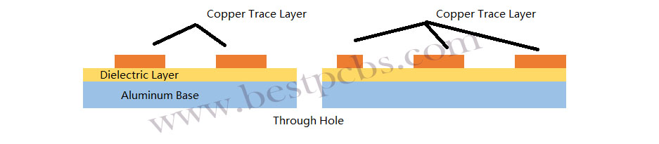
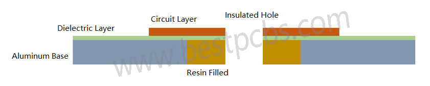
The manufacturing process of aluminum PCB is almost the same as normal FR4 PCB, except the lamination process of dielectric layer, aluminum and copper. This also is the biggest manufacturing difficult that faced by manufacturers, especially for multi-layer aluminum PCB. For the single & double sided aluminum PCB, the aluminum substrate we purchased from the manufacturers are laminated with dielectric, so we do not need to laminate again. In addition to this, the manufacturing process of aluminum PCB with insulated hole and without insulated hole are different.

  • Single-sided Aluminum PCB without insulated hole:

Cutting raw material (substrate laminated with dielectric layer) — Circuit layer generation (D-E-S) — Solder Mask – Silkscreen — Surface Treatment — Stripping — Drill Holes — Outline (V-cut – Routing – Die Punching) — QC — Package & Delivery

Single-sided Aluminum PCB without insulated hole
  • Single-sided Aluminum PCB with insulated hole:

Cutting raw material (substrate without laminated with dielectric layer) — Drill larger holes — Filled resin with holes — Lamination (dielectric layer + copper + aluminum base) — Circuit layer generation (D-E-S) — Solder Mask – Silkscreen — Surface Treatment — Stripping — Drill Holes — Outline (V-cut – Routing – Die Punching) — QC — Package & Delivery

Single-sided Aluminum PCB with insulated hole

Manufacturing Difficulties of Aluminum PCBs

Working with aluminum is not the same as working with FR4. It brings challenges, especially for a professional aluminum PCB manufacturer.

1. Mechanical Processing

Drilling holes on aluminum PCBs is possible, but the inner walls and board edges must be completely free of burrs. Even a slight burr can cause the board to fail the high-voltage test. Milling the outline is also quite difficult. The milling cutter used for FR4 PCB board has a relatively low hardness, while the milling cutter used for aluminum substrate has a high hardness. During the processing, the milling cutter for fiberglass board production has a high speed, while the milling cutter for aluminum substrate production has a speed at least 2/3 slower. As an alternative, punching with high-precision dies is often used—but die making requires exceptional skill, making this one of the main challenges in aluminum PCB manufacturing.

After punching, the edges must be clean and smooth, without any burrs or damage to the solder mask along the edges. Most factories use compound dies. Holes are punched from the circuit side, and the outline is punched from the aluminum side. This requires specific techniques, such as upward shearing and downward pulling during punching. Even after punching, the board’s warpage must be strictly controlled and should remain under 0.5%.

2. Protecting the Aluminum Surface During Processing

The aluminum base must remain completely free of scratches throughout the entire production process. Any direct contact with hands or chemicals can cause surface discoloration or oxidation, which are absolutely unacceptable. In many cases, re-polishing the aluminum surface is not allowed by customers. So, avoiding even the slightest damage to the aluminum layer is another major difficulty in the production process.

Some manufacturers use surface passivation treatments, while others apply protective films before and after hot air solder leveling (HASL). There are countless tricks and methods used to keep the surface clean—every factory has its own unique way of doing it.

3. High-Voltage Testing Requirements

For telecom power supply boards, 100% high-voltage testing is often mandatory. Some clients require DC testing, while others specify AC, typically at 1500V or 1600V for durations of 5 to 10 seconds. Every single board must pass this test.

Even the smallest contamination on the surface, burrs on holes or edges, jagged traces, or damage to the insulation layer can lead to arcing, leakage, or dielectric breakdown during testing. Boards that show signs of delamination or bubbling during the test are automatically rejected.

Despite these, trusted manufacturers like EBest Circuit (Best Technology) handle it well. Our experience helps solve such problems early in the process.

How Much Does Aluminum PCB Cost?

Many factors influence the pcb aluminium substrate price. These include:

  • Aluminum grade (6061, 5052, or 1060)
  • Thickness of copper and base layer
  • Board size and layer count
  • Surface finish type
  • Quantity ordered
  • Special design features (e.g., thermal vias, contours)

In general, aluminum PCBs cost more than FR4 boards. But for heat-sensitive designs, the added cost pays off in reliability.

For instance, a basic one-layer aluminum PCB may start from $1.0–$5.0 per unit in bulk. Complex designs with multi-layers or special finishes can go higher. EBest Circuit (Best Technology) offer competitive pricing without cutting corners. We also provide quick prototypes aluminium PCB substrate and full-scale production to meet your timeline and budget.

If you are interested in PCB aluminium substrate or aluminum PCB manufacturing, contact us today to learn more about our aluminum PCB board solutions. Let’s build something great together—strong, reliable, and ready for tomorrow’s tech.

You may also like