PCB manufacturing PCB manufacturing
Home > Blog

aluminum PCB circuit board

Aluminum PCB Circuit Board Complete Guide
Thursday, May 14th, 2026

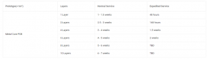
What Is an Aluminum PCB?

An aluminum PCB is a printed circuit board with an aluminum metal base. It is also called an aluminum core PCB, metal core PCB, or MCPCB. Its main purpose is to move heat away from components.

aluminum pcb circuit board

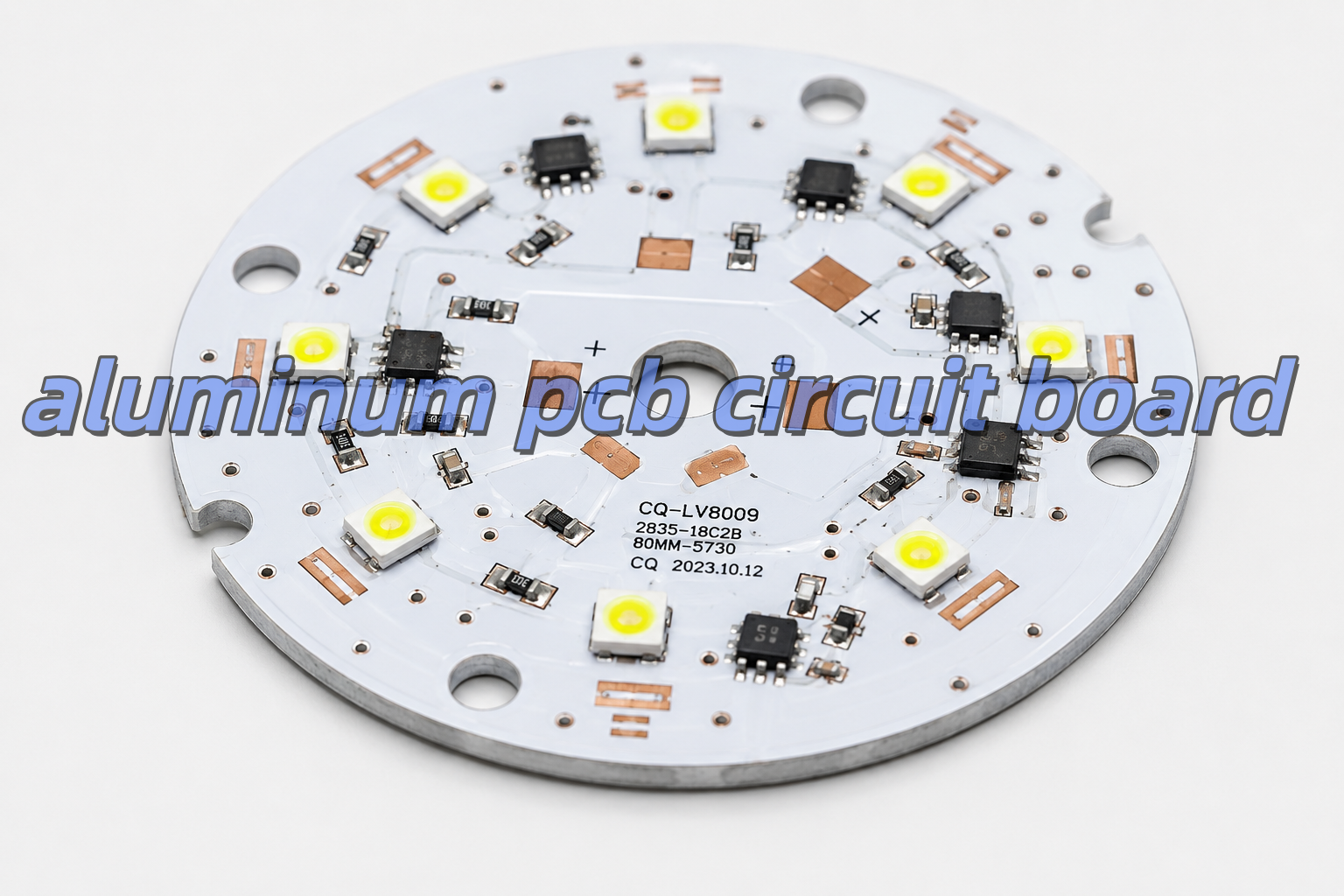
A normal FR4 PCB uses fiberglass as the base material. However, an aluminum PCB uses a metal base. Because aluminum transfers heat better than FR4, It helps reduce heat accumulation around high-temperature components.

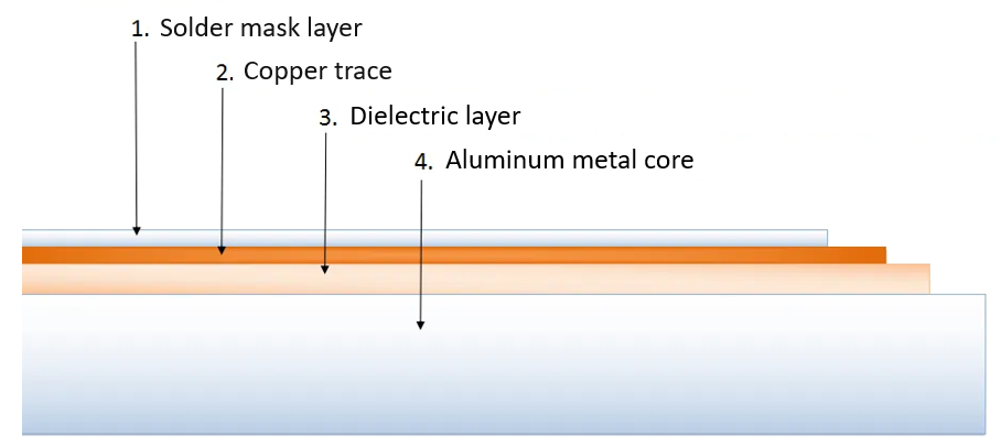
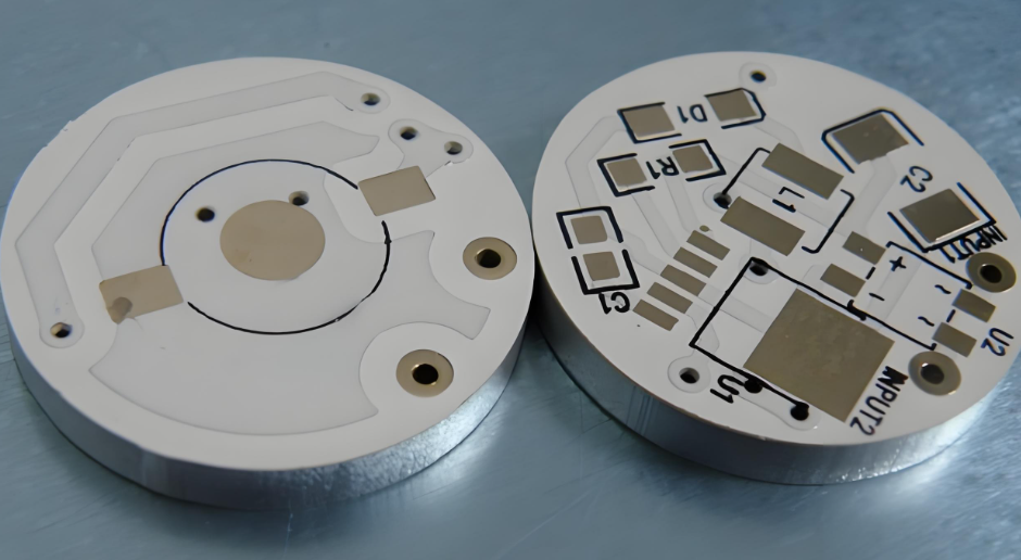
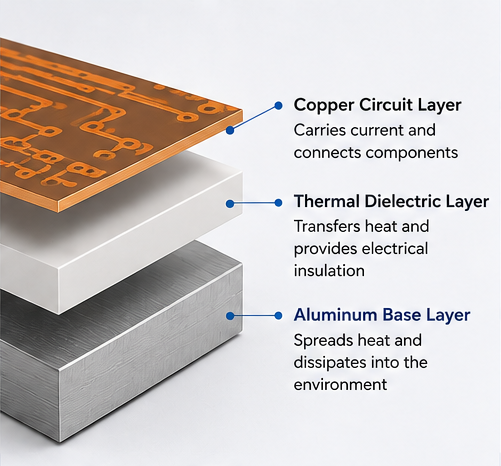
Typical aluminum-based printed circuit board has three main layers,as following:

LayerMain JobWhy It Matters
Copper Circuit LayerCarries current and signalsHelps the circuit work
Thermal Dielectric LayerMoves heat and insulates electricityControls heat and safety
Aluminum Base LayerSpreads heatKeeps the board cooler

The copper layer forms the circuit. The dielectric layer moves heat downward. Then, the aluminum base spreads the heat into the housing, air, or heat sink.

Because of this structure, aluminum PCB is a strong choice for LED lights, power boards, and other heat-sensitive products.

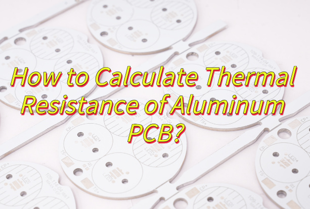
How Does an Aluminum PCB Circuit Board Dissipate Heat?

An aluminum PCB circuit board dissipates heat through a short heat path. First, heat starts at the component. Then, it moves into the solder joint and copper layer. After that, it passes through the dielectric layer. Finally, it reaches the aluminum base.

The heat path is usually:

Component → Solder Joint → Copper Layer → Dielectric Layer → Aluminum Base → Heat Sink

Heat dissipation path

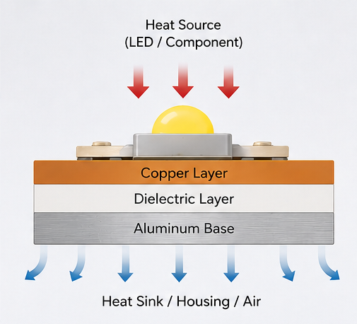
The dielectric layer is very important. It must move heat well. However, it must also keep electricity away from the aluminum base.

If this layer is poor, the board may still run hot. Therefore, the material quality matters. It is not enough to choose a board only because it has an aluminum base.

Also, the whole product design affects heat. For example, copper area, pad size, airflow, housing contact, and heat sink design all play a role. Therefore, the PCB should be reviewed together with the full product structure.

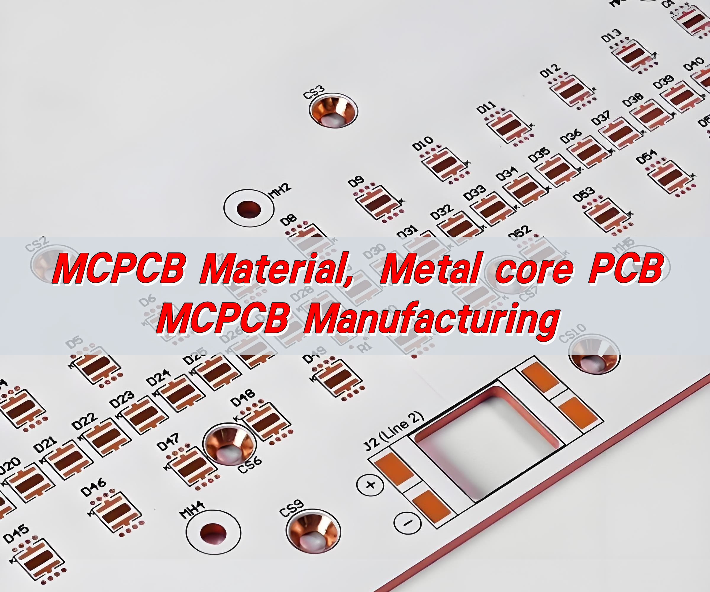
What Materials Are Used in Aluminum PCBs?

The aluminum PCB is made from copper foil, thermal dielectric material, aluminum base, solder mask, and surface finish. Each material affects heat control, electrical safety, soldering quality, and service life.

Copper Circuit Layer

The copper layer carries current. Also, it helps spread heat from component pads.

Copper ThicknessCommon Use
1 ozStandard LED lighting and simple circuits
2 ozHigher-current LED and power boards
3 oz or aboveHeavy-current power designs

For simple LED boards, 1 oz copper is often enough. However, for automotive lamps, power boards, and industrial modules, 2 oz copper may be better.

Thicker copper can carry more current. It can also reduce heat rise. However, it may increase production cost.

Thermal Dielectric Layer

The dielectric layer sits between the copper and the aluminum base. It has two jobs. First, it moves heat. Second, it provides electrical insulation.

Important points include:

  • Heat transfer
  • Insulation strength
  • Thickness
  • Heat resistance
  • Bonding strength
  • Long-term stability

A thinner dielectric layer can move heat faster. However, it must still meet the voltage and safety needs of the product.

Aluminum Base Layer

The aluminum base gives the PCB strength. It also spreads heat away from hot parts.

Aluminum ThicknessCommon Use
0.8 mmLight LED modules
1.0 mmGeneral lighting products
1.5 mmCommon aluminum PCB design
2.0 mm or aboveHigh-power or rugged products

For many LED boards, 1.5 mm is a common choice. However, larger lamps and industrial products may need 2.0 mm or thicker aluminum.

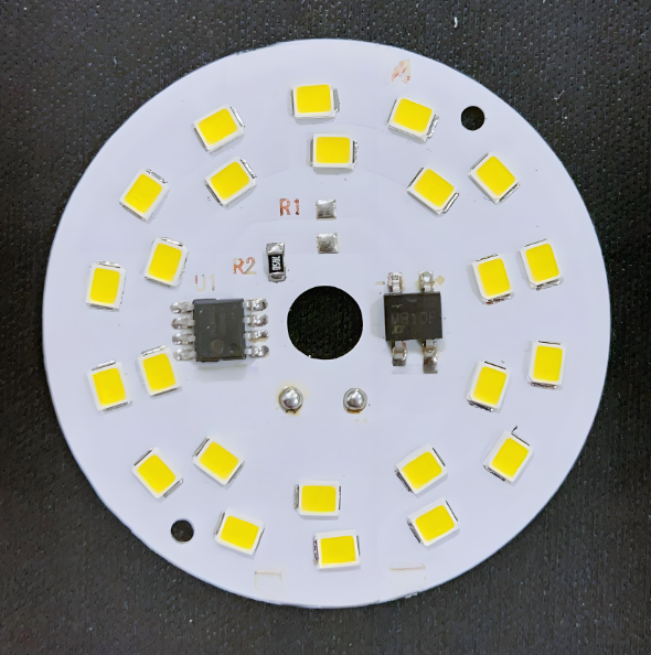
Solder Mask and Surface Finish

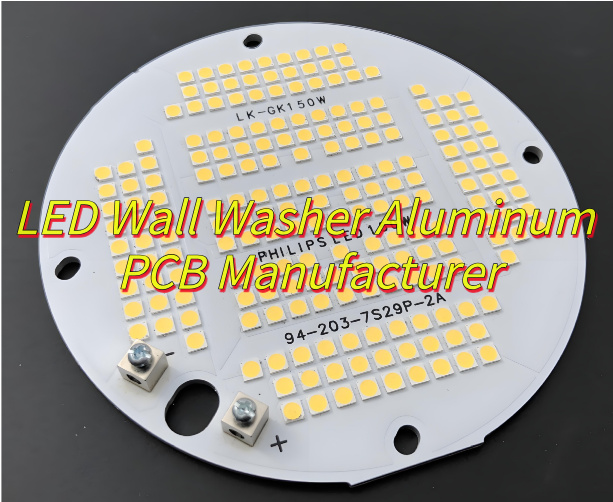
White solder mask is common for LED aluminum PCB. It reflects light better than dark solder mask. As a result, it helps improve light output.

Common surface finishes include lead-free HASL, ENIG, OSP, and immersion silver. For example, lead-free HASL is often used for standard LED boards. However, ENIG is better when the board needs a flat surface or fine-pitch parts.

aluminum-pcb-layer-structure

What Are the Common Aluminum PCB Stackup Types?

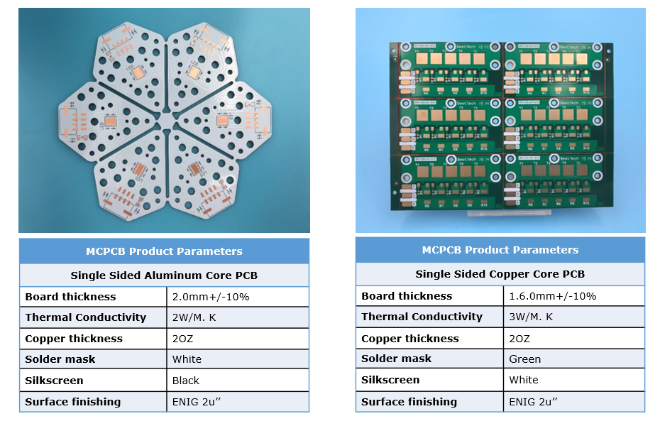
The most common aluminum PCB is single-sided. However, double-sided and hybrid aluminum PCBs are also used. The right choice depends on heat, current, routing space, and cost.

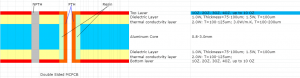
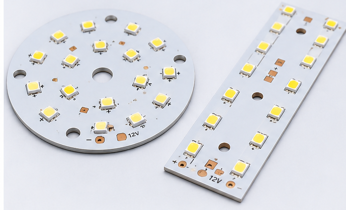
Single-Sided Aluminum PCB

Single-sided aluminum PCB is the most popular type. The circuit and parts are on one side. The aluminum base is on the other side.It is often used in:

  • LED bulbs
  • Street lights
  • High-bay lights
  • Panel lights
  • Power modules
  • Simple driver boards

Also, this type is cost-effective. It gives heat a short path to the aluminum base.

Double-Sided Aluminum PCB

Double-sided aluminum PCB has circuits on both sides. It gives more space for routing. Therefore, it is useful when the circuit is more complex.

However, it is harder to produce than a single-sided board. The via structure and insulation must be controlled well.

Hybrid Aluminum PCB

Hybrid aluminum PCB combines FR4 layers with an aluminum base. It is useful when a product needs both signal routing and heat control.

For example, FR4 can handle control signals. Meanwhile, aluminum can help remove heat from the power section.

What Thermal Conductivity Should You Choose for Aluminum PCB?

The right thermal conductivity depends on the product. For many LED products, 1.0–1.5 W/m·K is enough. However, high-power products often need 2.0 W/m·K or more.

Thermal ConductivitySuitable UseSimple Advice
1.0 W/m·KLow-power LED productsGood for simple lighting
1.5 W/m·KStandard LED lightingCommon choice
2.0 W/m·KMedium-power LED and power boardsBetter for more heat
3.0 W/m·K or higherHigh-power LED, automotive, industrial boardsGood for demanding designs

Higher thermal conductivity can move heat faster. However, it is not the only factor. Copper thickness, dielectric thickness, pad design, and heat sink contact also matter.

Therefore, do not choose material only by price. Also, do not choose the highest value without checking the real heat load.

For sealed lamps, automotive lights, medical devices, and industrial modules, it is better to leave more safety margin. As a result, the product can work more safely over time.

How Should You Design an Aluminum PCB Circuit Board Layout?

A good aluminum PCB layout should control heat, current, insulation, and mounting. The board is not only a circuit carrier. It is also part of the heat system.

Place Hot Parts Properly

High-power LEDs, MOSFETs, regulators, drivers, and power resistors should not be packed into one small area.

If hot parts are too close, hot spots may appear. As a result, some parts may age faster.

Therefore, spread hot parts when the circuit allows it. This helps the aluminum base spread heat more evenly.

Use Wider Copper for High Current

High-current traces should not be too narrow. Narrow copper creates more resistance. As a result, it creates more heat.

For high-current areas, use:

  • Wider traces
  • Copper pours
  • Thicker copper
  • Shorter current paths
  • Better thermal pads

Also, copper balance is important in LED arrays. Uneven copper may affect heat flow and soldering quality.

Design Thermal Pads Well

Thermal pads help move heat from components into the PCB. For LEDs and power parts, the pad should be large enough.

Also, the pad should connect well to the copper area. As a result, the LED junction temperature can be lower.

Control Clearance and Creepage

The aluminum base is conductive. Therefore, insulation design is very important.

Check these areas:

  • High-voltage spacing
  • Board edge clearance
  • Mounting hole isolation
  • Connector spacing
  • Exposed aluminum areas
  • Screw contact points

This is very important for LED drivers, medical power boards, industrial power supplies, and automotive electronics.

Design Mounting Holes Carefully

Mounting holes affect both strength and safety. If screws touch the aluminum base, the design must confirm whether the base is grounded or isolated.

In many products, screws press the PCB against a heat sink. This helps heat transfer. However, the structure must not damage the insulation layer.

What Are the Advantages and Disadvantages of Aluminum PCBs?

Aluminum PCBs offer strong heat control and good strength. However, they also have some limits. For example, they cost more than basic FR4 boards. Also, they are not ideal for very dense multilayer routing.

ItemAdvantagesLimits
Heat ControlGood for LED and power productsDepends on dielectric quality
StrengthRigid and stableNot flexible
CostGood value for heat productsHigher than standard FR4
DesignGood for simple power circuitsHarder for dense routing
ReliabilityReduces heat stressNeeds correct material choice
ReworkStable after assemblyRework may be harder

The main benefit is heat control. If heat affects your product, aluminum PCB is often a good choice.

However, the board must match the real use. A high-power street light should not use the same material as a small decorative lamp. Therefore, material selection should be based on heat load, current, and working environment.

What Are Aluminum PCBs Used For?

Aluminum PCBs are used in products that need fast and stable heat transfer. They are common in LED lighting, power electronics, automotive electronics, industrial equipment, medical devices, and aerospace systems.
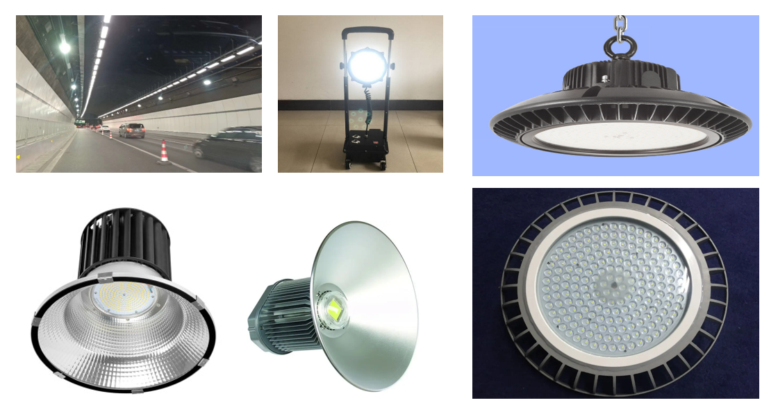
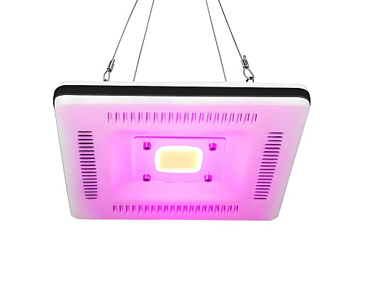
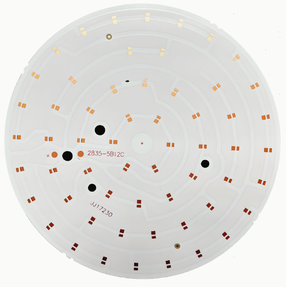
LED Lighting

LED lighting is one of the largest markets for aluminum PCB.Common products include:

  • LED bulbs
  • LED tubes
  • Street lights
  • High-bay lights
  • Stage lights
  • UV LED modules
  • Panel lights
  • Automotive LED lamps

In LED products, aluminum PCB helps control heat near the LED chip. As a result, it supports stable brightness and longer life.
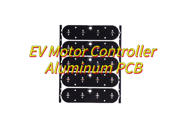
Power Electronics

Power electronics often create high heat in small spaces. Therefore, aluminum PCB can help reduce heat build-up.

Typical products include power supplies, DC-DC converters, motor drivers, inverters, voltage regulator modules, and charging modules.

Automotive Electronics

Automotive electronics must work under heat, vibration, and long use.

Aluminum PCBs are often used in LED headlights, taillights, signal lights, interior lighting, power modules, and battery-related boards.

Industrial Equipment

Industrial products often run for long hours. Therefore, stable heat control is important.

Aluminum PCBs can be used in automation equipment, industrial LED indicators, power modules, control cabinets, motor control boards, and machine vision lighting.

Medical and Aerospace Electronics

Medical and aerospace products often need stable heat behavior and strong process control.

Aluminum PCB may be used in medical lighting, diagnostic modules, UAV electronics, aerospace lighting, and compact power boards.

In these fields, traceability, inspection records, and stable quality are also important.

Why Are Aluminum PCBs Popular in LED Lighting?

led-aluminum-pcb

Aluminum PCBs are popular in LED lighting because LEDs create heat during use. If the heat is not removed well, brightness and life may drop.

An LED does not turn all electric energy into light. Some energy becomes heat. If this heat stays near the LED chip, the junction temperature rises.

High junction temperature may cause:

  • Lower light output
  • Faster lumen loss
  • Color shift
  • Shorter service life
  • More solder joint stress

Therefore, aluminum PCB is a strong choice for LED lighting. It creates a shorter heat path from the LED package to the lamp housing or heat sink.

Design ItemCommon Choice
Board TypeSingle-sided aluminum PCB
Board Thickness1.5 mm
Copper Thickness1 oz or 2 oz
Solder MaskWhite
Surface FinishLead-free HASL or ENIG
Thermal Conductivity1.5–2.0 W/m·K

White solder mask is common in LED aluminum PCB. It reflects light better than dark solder mask. Therefore, it supports both heat control and light output.

For high-power street lights, industrial lights, and automotive lamps, higher thermal conductivity and thicker copper may be needed.

Aluminum PCB Circuit Board vs FR4 PCB: Which Is Better?

Aluminum PCB is better for heat control. However, FR4 PCB is better for complex routing and low-heat circuits. Therefore, the better choice depends on your design goal.

Comparison ItemAluminum PCB Circuit BoardFR4 PCB
Base MaterialAluminum metal baseFiberglass epoxy
Heat ControlStrongLimited
Best UseLED, power, automotive lightingSignal, control, digital circuits
Circuit ComplexityBetter for simple heat designsBetter for multilayer routing
StrengthStrong and rigidGood for general electronics
CostHigher than basic FR4Lower for standard boards
Extra Heat SinkOften less neededOften needed for high power
Common ProductsLED lighting, power modules, industrial equipmentConsumer electronics, control boards

Choose aluminum PCB when heat is the main issue. It is suitable for LEDs, power modules, automotive lamps, and compact heat-sensitive products.

However, choose FR4 when the design needs many signal layers, fine-pitch IC routing, lower heat, and lower standard PCB cost.

In many products, both boards can be used together. For example, FR4 can handle signal control. Meanwhile, aluminum PCB can handle the LED or power section.

How to Select the Most Appropriate Aluminum PCB for Your Needs

To select the right aluminum PCB, start with heat load, current, voltage, environment, structure, and service life. Do not choose only by board thickness or price.

Check Heat Load First

Before selecting material, check:

  • Component power
  • Operating current
  • Ambient temperature
  • Enclosure design
  • Heat sink contact
  • Working hours
  • Product life target
  • Safety needs

A sealed outdoor lamp needs more heat margin than an open indoor module.

Select Thermal Conductivity

Match the thermal conductivity with the real use. For standard lighting, 1.5 W/m·K may be enough. However, compact high-power designs may need 2.0 W/m·K or higher.

Choose Copper Thickness

Copper thickness should match the current path. If the board carries higher current, use thicker copper or wider copper areas.

Otherwise, thin traces may create extra heat, even when the aluminum base is good.

Match Surface Finish

If the board uses simple LED packages, lead-free HASL may work well. However, if the board uses fine-pitch parts or needs a flatter surface, ENIG is often better.

Request DFM Review

A DFM review can find design and production risks before fabrication.

It should check trace width, spacing, mounting holes, thermal pads, solder mask openings, board edge clearance, surface finish, and assembly needs.

Finally, for high-power, automotive, medical, or industrial products, early review can reduce redesign cost and improve production stability.

EBEST Circuit: A Reliable Aluminum PCB Manufacturer

EBEST supports aluminum PCB fabrication, DFM review, component sourcing, PCBA assembly, and testing for heat-control electronic products.

For aluminum PCB projects, EBEST can review material choice, copper thickness, dielectric performance, solder mask, surface finish, layout risk, and assembly process before production.

EBEST Circuit CapabilityCustomer Value
Aluminum PCB FabricationSupports LED, power, automotive, industrial, and heat-control designs
DFM ReviewHelps reduce layout and production risks
PCB + PCBA ServiceSupports fabrication, sourcing, assembly, and testing
Material Selection SupportHelps match heat needs and board structure
Prototype to Batch ProductionSupports design test and production growth
Quality InspectionImproves consistency and delivery confidence

EBEST supports aluminum PCB projects for LED lighting, industrial equipment, automotive electronics, medical devices, aerospace modules, communication equipment, and power electronics.

Also, early manufacturing feedback can help customers reduce redesign work and improve delivery speed.

If you need an aluminum PCB circuit board, aluminum PCB assembly, or related PCB manufacturing support, EBEST can help from DFM review and PCB fabrication to component sourcing, assembly, and final testing. For project review or quotation support, contact sales@bestpcbs.com.

You may also like

Aluminum PCB Circuit Board Design & Manufacturer, Free DFM
Thursday, July 17th, 2025

Why choose aluminum PCB circuit board for your project? These high-performance boards combine superior thermal management with structural durability, making them ideal for LED, automotive, and power electronics. This guide covers their structure, benefits, design tips, and manufacturing process to help you make informed decisions.

  • Does heat dissipation design drag down product life?
  • Is it difficult to get professional support for small batches?
  • Does batch stability affect the pace of mass production?

EBest Circuit (Best Technology) Can Provide:

  • Accurate heat dissipation solution: Patented aluminum substrate (5.2W/m·K) with thermal simulation optimization reduces temperature rise by 35%.
  • Flexible cooperation model: 10 pieces minimum order, providing full technical support from design to mass production.
  • Reliable Batch Quality Inspection: Provide material traceability report + reliability test data for each batch.

Welcome to contact EBest Circuit (Best Technology) if you’re interested in aluminum PCB board: sales@bestpcbs.com.

What Is An Aluminum PCB Circuit Board?

An aluminum PCB circuit board (printed circuit board) is a specialized circuit board type constructed using an aluminum alloy base material instead of conventional fiberglass substrates like FR-4. This metal-core foundation serves as a heat dissipation solution, redirecting warmth away from temperature-sensitive electronic components.

These boards are formally categorized as metal-core PCBs (MCPCBs), with aluminum being the most widely adopted base material. The essential purpose centers on thermal management, aluminum efficiently absorbs and spreads heat generated during circuit operation, preventing damage to parts like LED emitters, power transistors, or voltage regulators. This characteristic makes aluminum PCBs a practical choice in applications demanding real-world cooling performance beyond traditional boards’ capabilities.

What Is An Aluminum PCB Circuit Board?

What Is the Structure of Aluminum PCB Board?

  • Circuit Layer (Copper Foil): Composed of electrolytic copper foil, typically 1 oz to 3 oz thickness. Serves as the conductive pathway for electrical signals.
  • Dielectric Layer (Thermal Insulation): A thermally conductive but electrically insulating material (e.g., epoxy resin with ceramic fillers). Transfers heat from the circuit layer to the metal substrate while preventing electrical shorts.
  • Metal Substrate (Aluminum Base): A thick aluminum plate (usually 1mm to 3mm thickness). Provides mechanical rigidity, heat dissipation, and acts as a heat sink for high-power components.
  • Adhesive Layer (Bonding Film): A thin adhesive film between the dielectric layer and aluminum substrate. Ensures strong adhesion and thermal conductivity between layers.

Aluminum PCB Circuit Board Specification

ParameterSpecification Range
Base Material5052/6061 Aluminum Alloy
Copper Thickness1oz – 4oz (35ÎŒm – 140ÎŒm)
Dielectric Layer50ÎŒm – 150ÎŒm
Max Operating Temp130°C – 150°C
Thermal Resistance0.5°C/W – 3.0°C/W
Breakdown Voltage2kV – 5kV
Surface FinishHASL, ENIG, OSP
Min Trace Width0.1mm – 0.3mm      
Min Hole Size0.3mm – 0.5mm
Panel Size500mm x 600mm (max)

What Are the Pros and Cons of Aluminum PCB Circuit Board?

Advantages of aluminum PCB circuit board:

  • Superior Thermal Management: Conducts heat 8-10x faster than standard FR4, preventing overheating in high-power LEDs, motor drives, and power converters.
  • Enhanced Durability: Resists vibration and mechanical stress better than fiberglass PCBs, ideal for automotive and aerospace applications.
  • Longer Component Lifespan: Stable thermal performance minimizes thermal expansion stress, reducing failure rates in power electronics.
  • Cost-Effective for High-Power Designs: Lower lifetime costs compared to FR4 + external cooling solutions in applications like LED lighting and industrial power supplies.
  • Eco-Friendly Material: 100% recyclable, aligning with green manufacturing and RoHS compliance.

Disadvantages of aluminum PCB circuit board:

  • Higher Upfront Cost: 20-30% more expensive than FR4 due to specialized dielectric layers and metal-core processing.
  • Limited Complexity: Mostly 1-2 layers; multilayer designs are rare and costly (e.g., hybrid constructions with FR4 sections).
  • Challenging Rework: Difficult to modify after production—drilling or cutting risks damaging the aluminum substrate.
  • Electrical Isolation Risks: Dielectric layer defects (e.g., voids) may cause shorts in high-voltage applications (>1kV).
  • Poor High-Frequency Performance: Higher parasitic capacitance distorts signals above 500MHz, making RF/microwave circuits impractical.
What Are the Pros and Cons of Aluminum PCB Circuit Board?

What Are Aluminum PCB Board Used for?

  • High-Power LED Lighting – Commercial lighting, automotive headlamps, backlight units.
  • Power Electronics – Switch-mode power supplies, motor controllers, solar inverters.
  • Automotive Systems – Electric vehicle battery modules, engine control units, LED taillights.
  • Audio Amplifiers – High-fidelity amplifiers, professional audio equipment, RF power modules.
  • Renewable Energy – Solar panel junction boxes, wind turbine converters, energy storage systems.
  • Medical Devices – Surgical lighting, diagnostic imaging equipment, laser therapy systems.
  • Industrial Controls – Programmable logic controllers (PLCs), sensor modules, robotics.
What Are Aluminum PCB Board Used for?

How to Design Aluminum LED PCB for Better Heat Dissipation?

Methods about how to design aluminum LED PCB for better heat dissipation:

  • Choose High-Thermal-Conductivity Dielectric Layers‌: Use ‌≄2.0 W/mK‌ dielectric materials (e.g., Bergquist HT-07000) to bridge heat from LEDs to the aluminum base.
  • Maximize Copper Thickness for Power Traces‌: Prioritize ‌2–4 oz copper‌ to reduce resistive heating and improve thermal spreading.
  • Implement Thermal Vias Under LED Pads‌: Place ‌arrays of vias (0.3–0.5mm diameter)‌ beneath LED footprints to direct heat to the aluminum core.
  • Avoid Thermal Islands in Layouts‌: Connect all high-power components to large copper pours, ensuring heat paths are ‌continuous and low-impedance‌.
  • Balance Copper Distribution‌: Symmetrical copper layers prevent warping and reduce ‌localized hotspots‌ during thermal cycling.
  • Optimize LED Spacing‌: Maintain ‌≄5mm spacing‌ between high-power LEDs to minimize cross-heating effects.
  • Use Thermal Simulation Early‌: Tools like ‌ANSYS Icepak‌ or ‌Mentor FloTHERM‌ can predict hotspots before prototyping.

How Are Aluminum PCBs Made?

Aluminum PCB Manufacturing Process:

1. Material Cutting: Cut aluminum alloy substrate (e.g., 1050, 6061) to specified dimensions.
2. Surface Cleaning: Clean aluminum and copper foil surfaces to remove oils, oxides, or contaminants.
3. Dielectric Layer Coating: Apply thermally conductive epoxy or prepreg to the aluminum substrate.
4. Copper Foil Lamination: Bond electrolytic copper foil (1–3 oz) to the dielectric layer under heat and pressure.
5. Circuit Etching: Print photoresist, expose to UV light, and etch excess copper with alkaline/acidic solutions.
6. Drilling: Machine-drill via holes using carbide bits, ensuring positional accuracy (±0.05mm).
7. Through-Hole Plating: Electroplate drilled holes to create conductive vias (copper thickness ≄1.5 mils).
8. Surface Finish Application: Apply HASL, ENIG, or OSP to protect copper and enhance solderability.
9. Thermal Stress Testing: Subject boards to thermal cycling (-40°C to +125°C) to validate durability.
10. Final Inspection & Packing: Conduct 100% visual and dimensional checks before packaging.

How Are Aluminum PCBs Made?

Why Choose EBest Circuit (Best Technology) as Aluminum PCB Manufacturer?

Reasons why choose EBest Circuit (Best Technology) as aluminum PCB manufacturer:

  • Certified Compliance (ISO 9001, UL, RoHS, ISO 9001, IATF 16949 ): Mitigates regulatory risks and ensures products meet global standards for safety and environmental compliance.
  • Free DFM (Design for Manufacturability) Analysis: Optimizes PCB layouts to reduce material waste, lower production costs, and avoid late-stage design revisions.
  • Turnkey Solutions – Full-service PCB manufacturing from design to delivery, accelerating your product’s time-to-market.
  • Fast Turnaround – 24-hour rapid prototyping and industry-leading production lead times.
  • Stable Supply Chain – Guaranteed material availability with minimal risk of delays.
  • Responsive Support – Dedicated customer service with a 2-hour response guarantee for urgent requests.
  • Competitive & Transparent Pricing – No hidden costs, offering the best value without compromising quality.
  • Stringent Quality Control with 100% Inspection: Eliminates hidden defects, reduces rework costs, and ensures reliability in high-current/thermal applications.

If you have any request for aluminum PCB, welcome to contact us: sales@bestpcbs.com.

You may also like

Aluminum PCB Circuit Board | Aluminum PCB Design & Prototype
Tuesday, October 8th, 2024

What is Aluminum PCB Circuit Board?

An aluminum PCB, also known as an aluminum circuit board, is a type of metal core printed circuit board that uses aluminum as its base material. Unlike traditional PCBs, which are typically made with fiberglass, aluminum PCBs offer superior heat dissipation. This makes them ideal for high-power applications where excess heat can damage sensitive components. Aluminum PCBs are widely used in industries such as LED lighting, automotive, and power equipment because they provide better thermal management.

Aluminum PCBs are made from a combination of the following materials:

  • Aluminum Substrate: The base layer, responsible for mechanical support and heat dissipation.
  • Dielectric Layer: This layer provides insulation between the conductive layer and the aluminum base, while also helping with thermal transfer.
  • Conductive Layer: Made of copper, this layer is etched to form the circuit pattern and provides electrical connectivity.
  • Solder Mask Layer: This is a protective layer to protect the traces.
Aluminum PCB Circuit Board | Aluminum PCB Design & Prototype

Types of Aluminum PCB

Aluminum circuit board is a kind of metal base copper clad plate with good heat dissipation function, the main types include single-sided aluminum PCB, double-sided aluminum PCB and multi-layer aluminum PCB. ‌

Single sided aluminum PCB

The single-sided aluminum substrate is composed of a conductive graphic layer and an insulating material plus aluminum plate, which is relatively simple in structure and suitable for the installation and connection of some basic electronic components.

Double sided aluminum PCB

The double-sided circuit aluminum substrate has two layers of conductive graphics layer and the insulating material plus aluminum plate superimposed together, providing a larger circuit layout space and better heat dissipation effect, which is often used in electronic devices requiring higher integration and better heat dissipation performance.

Multilayer aluminum PCB

Multi-layer printed aluminum-based circuit board consists of three or more layers of conductive graphic layer and insulating material and aluminum plate alternately laminated together, with complex circuit design and excellent heat dissipation performance, suitable for high-end applications such as LED lighting, automotive electronics ‌.

In addition, there are other special types of aluminum-based circuit boards, such as flexible aluminum substrates, mixed aluminum substrates, etc. Flexible aluminum substrate has excellent electrical insulation, flexibility and thermal conductivity, and is suitable for product design in various shapes and angles. The hybrid aluminum substrate is a multilayer component made of conventional FR-4 bonded to an aluminum substrate with a thermoelectric medium, designed to improve heat dissipation and rigidity, and used as a shield ‌.

Aluminum PCB Features

The aluminum substrate, a metal-based cooling plate (including aluminum, copper, and iron substrates), is made from a low-alloyed Al-Mg-Si series high-plastic alloy plate. This material offers excellent thermal conductivity, electrical insulation, and mechanical processing capabilities. When compared to traditional FR-4 materials, aluminum substrates of the same thickness and line width can carry higher currents. Additionally, they can withstand voltages up to 4500V and have a thermal conductivity greater than 2.0, making aluminum substrates the preferred choice in the industry.

● Surface mount technology (SMT);

● Very effective treatment of thermal diffusion in circuit design;

● Reduce product operating temperature, improve product power density and reliability, extend product service life;

● Reduce product volume, reduce hardware and assembly costs;

● Replace fragile ceramic substrate for better mechanical durability.

Aluminum PCB vs. Copper PCB

Both aluminum and copper PCBs have their own advantages, but they cater to different applications:

1. Thermal Conductivity

    In general, the higher the thermal conductivity, the more efficient the heat transfer, resulting in better heat dissipation and a longer lifespan. Among metal substrates, copper substrates offer the best thermal conductivity, outperforming aluminum substrates.

    2. Electrical Conductivity

    Both aluminum and copper are metals and conduct electricity, though their exact levels of conductivity differ. In terms of electrical conductivity, copper is significantly superior to aluminum. In applications that require high electrical conductivity, copper is the ideal choice.

    3. Resistance

    Resistance is crucial in PCB design as it affects the overall functionality and stability of the components. Given that copper has a higher density than aluminum, its resistance is generally lower. Therefore, in applications requiring thinner circuits and faster power transmission, copper is the better option.

    4. Weight

    Due to copper’s higher density per unit area, copper PCBs are much heavier than aluminum PCBs with the same design.

    In applications where lightweight structures are critical, aluminum is the preferred material. On the other hand, applications where weight is not a major concern often favor the use of copper.

    5. Applications

    Aluminum substrates are somewhat specialized. They are mainly used in energy-saving lighting products such as indoor lighting, energy-efficient lighting, and street lights. Copper substrates are suitable for high-power lighting equipment like car headlights, tail lights, and some high-tech electronics.

    6. Manufacturing Process

    The manufacturing process for aluminum-based PCBs is simpler than that for copper-based PCBs, which also impacts their production time and delivery schedules. Below is aluminum PCB and copper core PCB that made by EBest Circuit (Best Technology):

    Aluminum PCB Circuit Board | Aluminum PCB Design & Prototype

    Aluminum PCB Manufacturing Process

    The manufacturing process for aluminum PCBs involves several steps to ensure high quality and performance. Here is a basic manufacturing process of aluminum PCB:

    1. Substrate Selection and Preprocessing

      Aluminum alloys with high thermal conductivity, such as the 5052 and 6061 series, are selected as the base material. The aluminum sheet is first cut and cleaned to remove surface grease and impurities, ensuring proper adhesion for subsequent processes.

      2. Chemical Etching of Patterns

      Photosensitive ink is used to form the desired circuit patterns on the aluminum surface. After exposure and development, the ink-covered areas protect the underlying aluminum from being etched by chemicals, while the unprotected areas are etched away, forming the circuit pattern.

      3. Insulation Layer Deposition

      To achieve electrical isolation, an insulating material, usually thermosetting resin or ceramic-filled epoxy resin, is deposited on the aluminum substrate. This step is typically completed using screen printing or inkjet printing technology to ensure a uniform and appropriately thick insulation layer.

      4. Metallization

      Creating conductive paths on the insulation layer is a key step. Copper foil is deposited onto the insulation layer using methods such as electroplating, sputtering, or chemical copper deposition. This copper foil serves as the conductive layer for connecting LED chips and other components.

      5. Drilling and Metallization

      Holes are drilled in the board according to the design to achieve electrical connections between different layers. The hole walls are then metallized to ensure good conductivity inside the holes.

      6. Surface Treatment

      To improve solderability and corrosion resistance, the aluminum substrate undergoes additional surface treatments, such as tin spraying, gold plating, or silver plating.

      7. Assembly and Testing

      LED chips, resistors, capacitors, and other components are soldered onto the circuit board to complete the assembly. Here you can see the whole manufacturing process of aluminum metal core PCB.

      What Affects Aluminum PCB Circuit Board Price?

      First of all, ‌ raw material cost ‌ is one of the important factors affecting the price of aluminum based circuit board. The raw materials of aluminum substrate include aluminum substrate and other auxiliary materials, such as insulating layer materials. The price fluctuation of aluminum substrate will directly affect the production cost of aluminum substrate, and then affect its market price. In addition, the cost of electricity is also a part of the production process cannot be ignored, the fluctuation of electricity price will further affect the production cost ‌.

      Secondly, ‌ market supply and demand ‌ is also a key factor in determining the price of aluminum-based circuit boards. If demand increases and supply is insufficient, prices will naturally go up. On the other hand, if there is an oversupply, the price will fall. Changes in demand in the construction, automotive and other industries, as well as changes on the supply side such as the construction of new plants or the closure of old plants, will have a direct impact on the price of aluminum-based circuit boards ‌.

      ‌The macroeconomic environment ‌ also has an important impact on the price of aluminum-based circuit boards. When economic growth is expected to be good, the demand for aluminum substrate in related industries increases, driving up prices; The expectation of economic recession will lead to a decline in demand and pressure on aluminum substrate prices ‌.

      ‌Policies and regulations ‌ is also one of the factors affecting the price of aluminum-based circuit boards. The government’s environmental protection policies, trade policies and industry subsidies will have an impact on the aluminum substrate market. For example, environmental policies that limit production may reduce supply and push up prices; The establishment of trade barriers may affect the import and export of aluminum substrate, and then affect the domestic market price.

      Aluminum PCB Production Capability – EBest Circuit (Best Technology)

      EBest Circuit (Best Technology) is known for its strong production capability when it comes to aluminum PCBs. Our manufacturing facilities are equipped with the latest technology to produce high-quality aluminum PCBs that meet industry standards. We have the ability to produce single-sided, double-sided, and multi-layer aluminum PCBs, below you can see our capability of aluminum PCBs:

      Aluminum PCB Circuit Board | Aluminum PCB Design & Prototype

      Applications of Aluminum PCB

      Aluminum PCBs are used in a variety of applications, particularly where heat management is crucial:

      • LED Lighting
      • Automotive Electronics
      • Power Supplies
      • Consumer Electronics
      • Medical
      • Household appliance
      Aluminum PCB Circuit Board | Aluminum PCB Design & Prototype

      FAQs about Aluminum PCB Circuit Board

      1. What is the main advantage of aluminum PCBs?

        Aluminum PCBs excel in thermal management, making them perfect for heat-sensitive applications.

        2. Are aluminum PCBs expensive?

        No, aluminum PCBs are generally affordable, making them a cost-effective option for many industries.

        3. Can aluminum PCBs be used in consumer electronics?

        Yes, aluminum PCBs are commonly used in consumer electronics, especially in devices that generate significant heat.

        4. What industries commonly use aluminum PCBs?

        Industries such as automotive, LED lighting, and power supplies frequently use aluminum PCBs due to their thermal properties.

        5. Is aluminum PCB better than copper PCB?

        It depends on the application. Aluminum is better for heat dissipation, while copper excels in electrical conductivity.

        You may also like