PCB manufacturing PCB manufacturing
Home > Blog

aluminum pcb thermal conductivity

Long Aluminum PCB: LED Lighting, Flatness and Manufacturing
Friday, October 9th, 2026

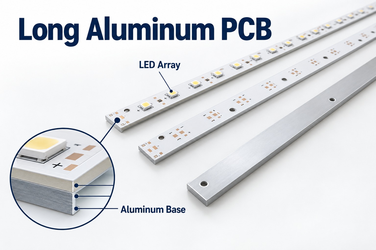
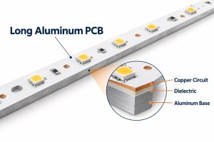
A long aluminum PCB is an elongated metal-core circuit board that carries an LED array and transfers heat toward the light fixture’s heatsink. Its copper circuit is separated from the aluminum base by a thermally conductive electrical insulation layer. For a 1.2-meter design, the main questions are usable manufacturing length, flatness after processing, and compatibility with the assembly line—not length alone.

At EBest Circuit, we support aluminum PCB fabrication, component sourcing and PCB assembly. Send your board drawing and thermal requirements for a DFM review before fixing the material or production layout.
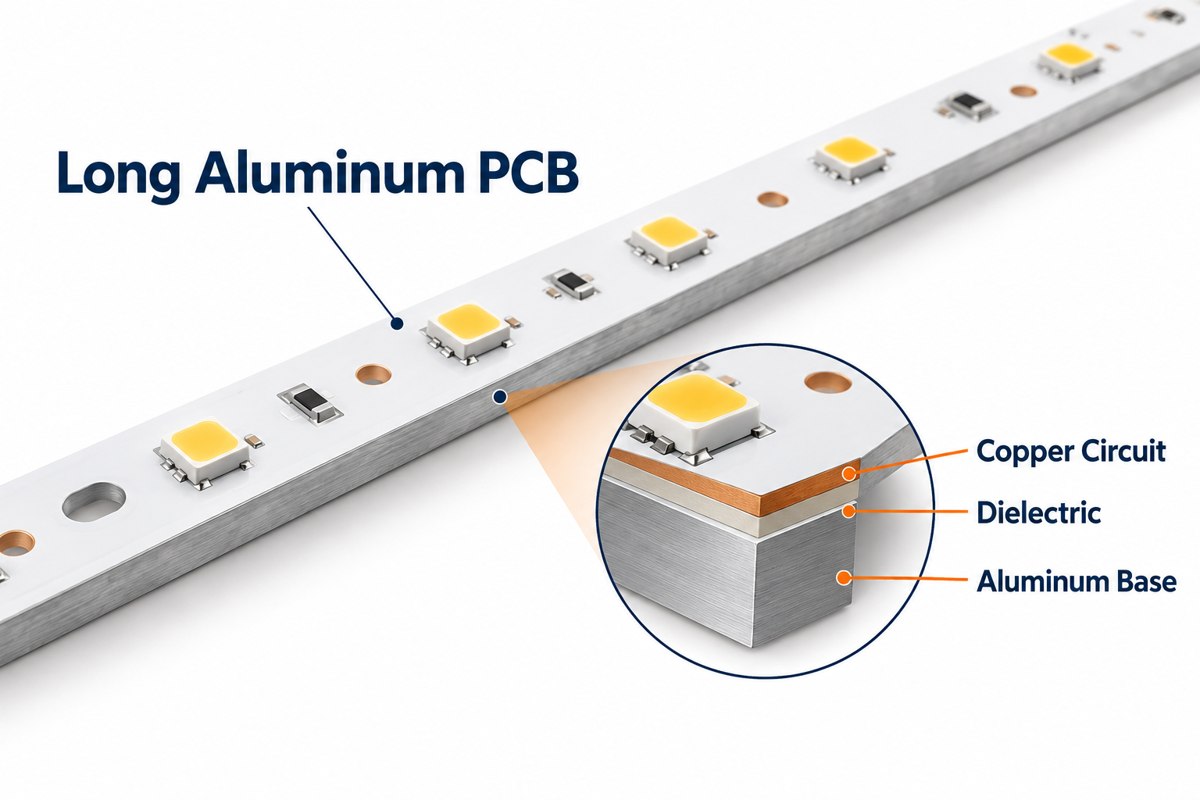
Long aluminum LED PCB with a magnified copper, dielectric and aluminum base cross section

Key Takeaways

  • A long aluminum PCB combines electrical routing with a metal heat-spreading base for linear LED lighting.
  • Our MCPCB capability table lists 480 × 1180 mm regular aluminum large-sheet dimensions and 1600 × 480 mm special single-sided processing. Finished-board and assembly dimensions require separate confirmation.
  • A 1.2-meter strip needs an agreed flatness limit, measurement condition and heatsink mounting arrangement.
  • Dielectric options include 1, 2 and 3 W/m·K grades. Thickness and thermal resistance matter alongside conductivity.
  • Long-board process planning must address support, profiling, handling and soldering—not just the laminate size.
  • Marine lighting requires coordinated moisture, corrosion and enclosure design. A bare PCB does not establish a luminaire’s environmental rating.
  • Quote files should define the mechanical drawing, material, quantities and acceptance tests, with BOM and placement data for PCBA.

What Is a Long Aluminum PCB?

A long aluminum PCB is a rigid aluminum-based circuit board whose elongated shape suits a linear product, such as an LED light bar. “Long” describes the geometry; it is not a separate electrical technology or a standardized length class.

A typical single-sided aluminum PCB stackup contains these layers:

Layer Function
Copper circuit Connects LEDs, resistors and power connections.
Thermally conductive dielectric Electrically isolates the circuit from the metal while conducting heat.
Aluminum base Supports the board and spreads heat toward the mounting surface.

Solder mask covers the circuit except at exposed pads. Aluminum boards belong to the metal core PCB family; the metal base is not automatically an electrical ground connection.

Why Are Long Aluminum PCBs Used in LED Lighting?

Long aluminum PCBs fit continuous LED rows while providing a heat-transfer path to a linear heatsink or housing. A single board can also reduce the number of connectors between shorter LED modules.

They suit architectural light bars, linear fixtures and selected marine lighting assemblies. The board supports LED placement along the optical path, but uniform brightness still depends on the driver, LED spacing, bin selection and optical design.

We can bring the aluminum light board and a separate FR-4 driver or control board into the same PCB/PCBA project. This lets the mechanical interfaces, connectors and test requirements be reviewed together. It does not require forcing a complex driver circuit onto the LED board.

How Long Can an Aluminum PCB Be?

Our MCPCB capability table lists 1600 × 480 mm for special single-sided aluminum processing, alongside a regular aluminum large-sheet size of 480 × 1180 mm. These figures describe different processing categories, not a blanket maximum for every finished board.

A 1200 mm finished strip exceeds the listed regular sheet length. It therefore needs a special-process review, including tooling space and the usable area remaining after manufacturing margins.

Capability item Listed range or condition
Regular aluminum large sheet 480 × 1180 mm
Special single-sided aluminum processing 1600 × 480 mm; project review required
Regular processing thickness 0.8–3.0 mm
Thicker material 4.0 and 5.0 mm by material order and confirmation
1 oz copper line/space 0.20/0.20 mm regular; 0.15/0.15 mm special

These parameters are not guaranteed in every combination. Before releasing a long-board order, confirm three dimensions separately: the finished PCB, the fabrication panel, and the assembly carrier or panel. The printer, placement machine, reflow transport and inspection equipment each need to accommodate the approved format.

Why Is Flatness Difficult on a 1.2-Meter Aluminum PCB?

A 1.2-meter aluminum PCB makes small curvature more visible because the unsupported span is long. Its copper, dielectric and aluminum layers also respond differently to heating and cooling.

  • Material and copper distribution: an asymmetric construction can develop uneven stress through processing.
  • Thermal history: curing and soldering cycles can change the board’s free-state shape.
  • Profiling and support: a narrow strip may move when it is separated from a larger panel.
  • Handling and mounting: unsupported lifting or forcing the strip against uneven screw positions can introduce deformation.
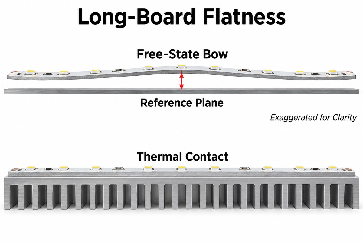
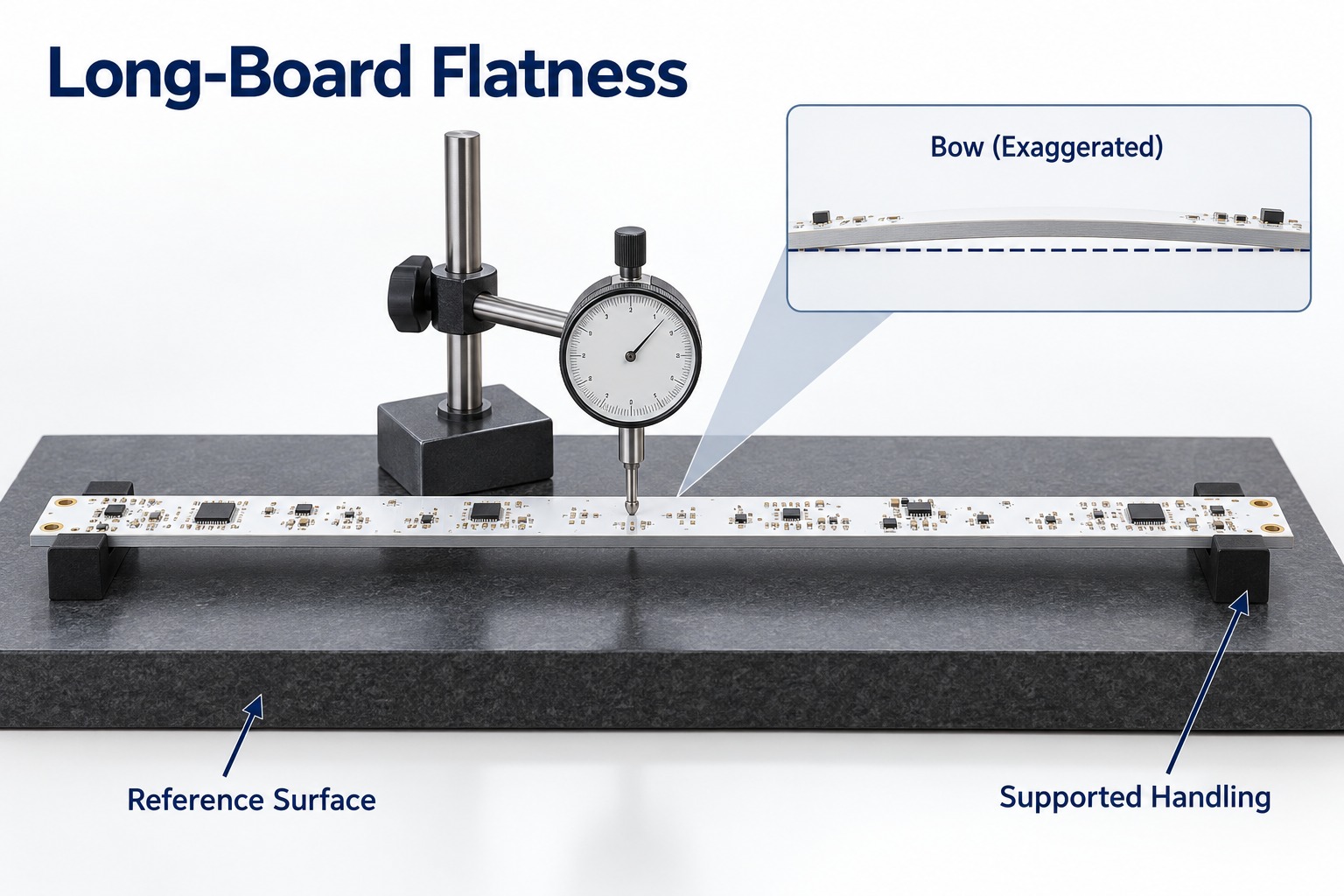
Exaggerated free-state bow in a long LED board compared with flat contact on a heatsink

Specify flatness in the drawing with a measurement method. State whether the board is free or restrained, where it is supported, and whether inspection occurs before or after assembly. For illustration only, 0.5% of 1200 mm is 6 mm: a percentage that appears small can allow a large gap. This is not a recommended acceptance limit or an IPC test calculation.

How Do We Maintain Yield on Long, Narrow Aluminum PCBs?

Our starting point is a DFM review that connects the long-board layout with a practical fabrication and inspection plan. The detailed support method and process settings must be qualified for the selected design.

For long, narrow boards, the production review should resolve:

  1. Material and panel layout: confirm the selected laminate is available in the required usable size. Include tooling and handling margins.
  2. Support during processing: establish how the strip is held during machining, inspection and any assembly operation.
  3. Profile and hole quality: check edge clearances, mounting-hole positions and burr control against the drawing.
  4. First-article release: verify dimensions, flatness and electrical results before approving the production arrangement.
  5. Handling and packing: support the board along its length and prevent bending loads during transport.

For assembly, add stencil support and a soldering profile validated on the actual aluminum construction. Aluminum PCB design decisions should be reviewed before tooling is ordered; correcting a support or mounting problem after production starts adds rework. A meaningful yield figure must refer to a defined product and inspection plan, not an unrelated short-board run.

How Should You Choose Dielectric Thermal Conductivity for an LED Aluminum PCB?

Start by comparing the available 1, 2 and 3 W/m·K dielectric grades against the LED temperature budget, then check dielectric thickness and electrical insulation requirements. Our material table lists higher-conductivity 3–8 W/m·K options as requiring a material inquiry.

Aluminum PCB thermal conductivity is often quoted as the dielectric value—not the conductivity of the aluminum base or the complete board. Our listed regular dielectric thickness for specified material families is 100–110 ”m; 150 and 200 ”m options require confirmation.

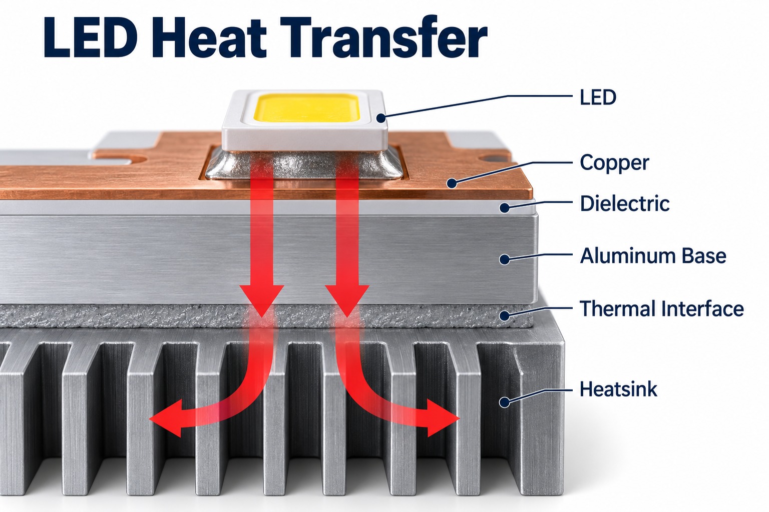
For an ideal uniform layer, thermal resistance is proportional to thickness divided by conductivity and heat-transfer area: R = t/(kA). At equal area, doubling conductivity halves that layer’s calculated resistance; doubling thickness cancels that benefit. The complete LED-to-ambient path also includes the package, solder connection, mounting interface and heatsink.
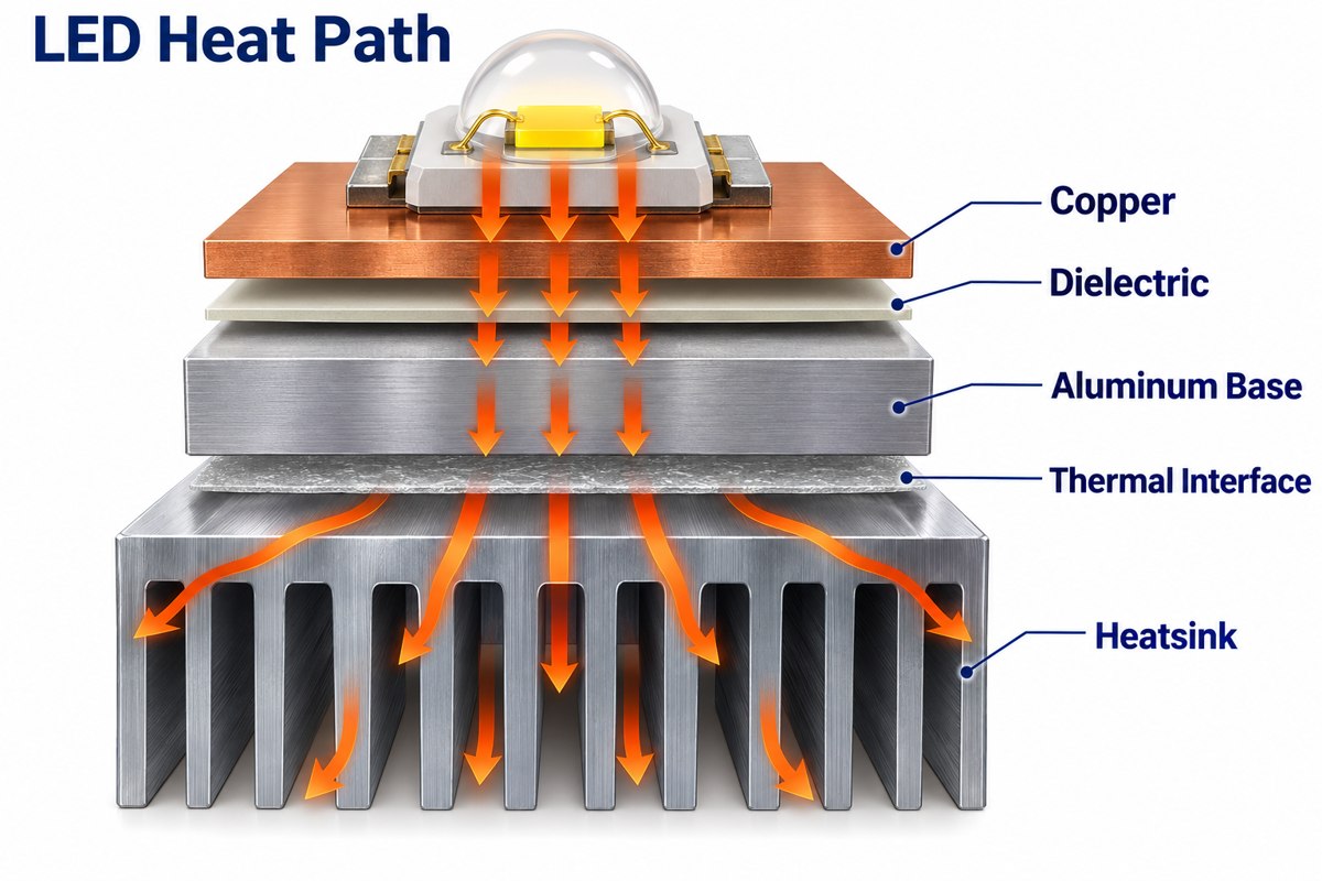
Illustrated heat path from an LED through the dielectric and aluminum base to a heatsink

Request the exact laminate grade and its test method rather than comparing unlabeled conductivity numbers. Confirm insulation performance separately, and validate LED temperature in the intended housing at the specified operating current and ambient temperature. Higher conductivity alone does not establish an acceptable junction temperature.

What Should Be Checked for Marine LED Lighting PCBs?

Marine LED lighting PCBs need checks for moisture exposure, corrosion paths and insulation, together with the luminaire’s sealing and heat-transfer design. Interior cabin lighting and an exposed exterior fixture do not face identical conditions.

  • Water entry and condensation: define the expected exposure and how the enclosure, seals and cable entries manage it.
  • Exposed metal: review board edges, mounting holes and dissimilar-metal contacts for the intended environment.
  • Coating or potting: specify coverage and keep-outs for LEDs, connectors and heat-transfer surfaces; check material compatibility.
  • Mechanical installation: assess mounting stress, vibration and connector strain relief.
  • Electrical protection: define operating voltage, insulation requirements and the driver’s protection needs.
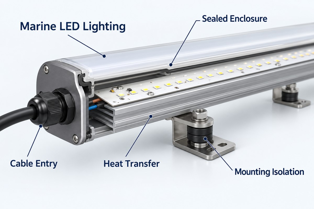
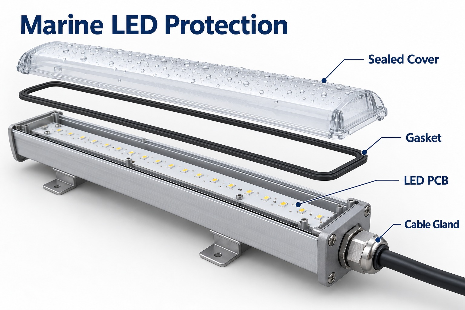
Conceptual cutaway of a marine linear LED light showing enclosure, cable entry, mounting isolation and heat transfer

The qualification plan should identify tests for the PCB, PCBA and complete fixture separately. A coating on the board does not by itself establish an IP rating, and a company quality-system certificate is not marine product approval.

What Tests Are Important for Long Aluminum PCBs?

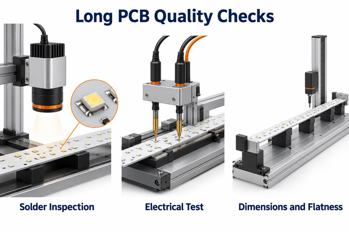
Long aluminum PCBs need dimensional and flatness checks plus electrical continuity and short-circuit testing. Assembled LED boards also need solder-joint inspection and the functional checks defined for the lighting circuit.

Stage Check What it verifies
Bare PCB Dimensions, holes and flatness Fit against the released mechanical drawing
Bare PCB Open/short electrical test Circuit connectivity against approved data
PCB or PCBA, as specified Insulation resistance or dielectric withstand Insulation under the agreed test conditions
PCBA Paste and solder inspection Deposit quality, placement and inspectable solder joints
PCBA Powered functional test LED polarity, string operation and specified electrical behavior
Qualification build Thermal and environmental validation Performance in the defined installation and exposure
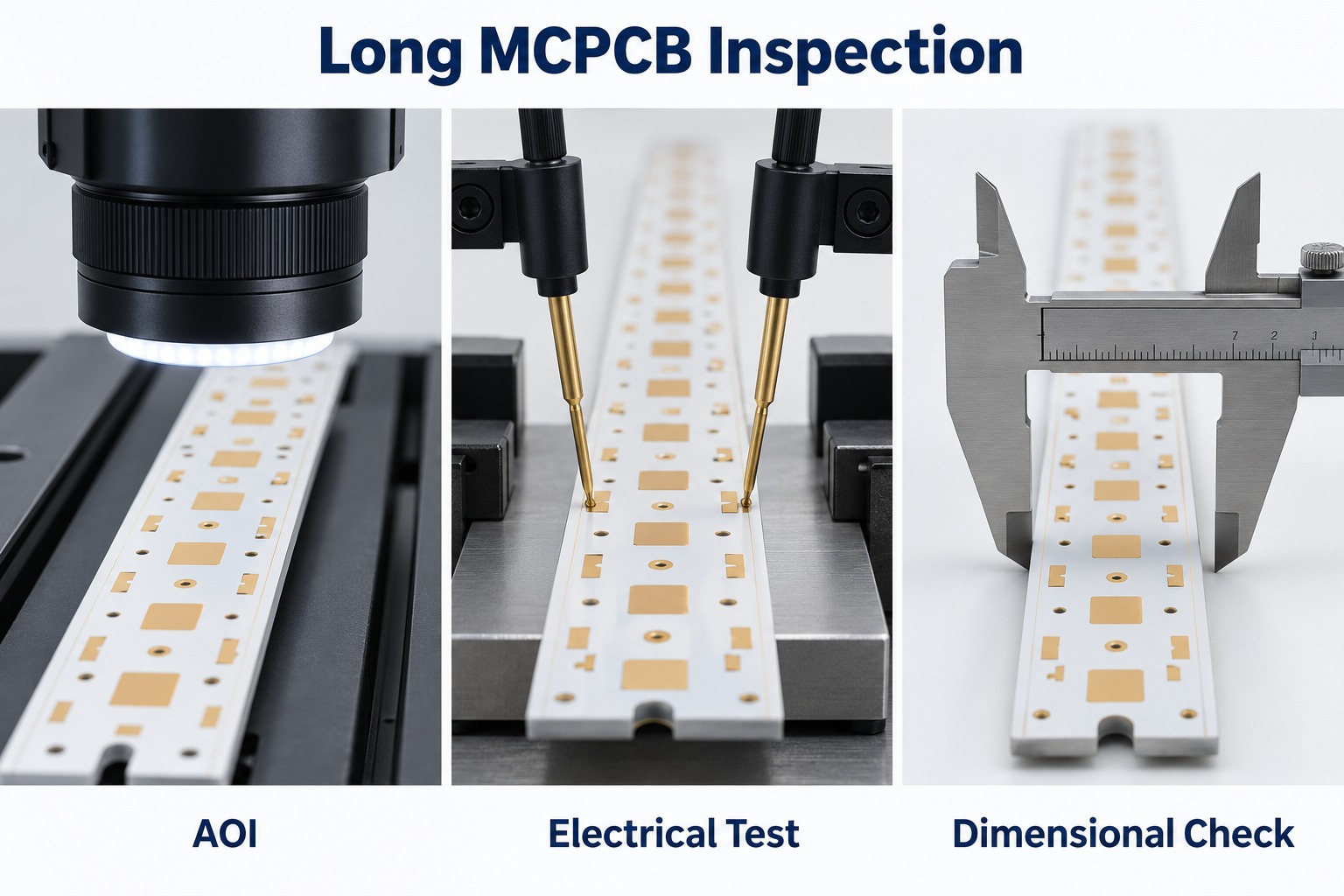
Conceptual optical inspection, electrical probing and dimensional checking of long LED PCBs

Our listed inspection resources include AOI, electrical testing, dimensional measurement, SPI, X-ray and functional testing. The selected methods, equipment size coverage and acceptance criteria must match the actual long-board project. X-ray is relevant where a joint cannot be assessed adequately by optical inspection; it is not a substitute for a functional test.

Agree the test voltage, duration, limits and sampling plan before ordering. Separate qualification tests from routine production tests so neither cost nor acceptance depends on an unstated assumption.

What Should Buyers Ask an Aluminum PCB Manufacturer?

Ask an aluminum PCB manufacturer to confirm the usable finished-board size and the corresponding assembly route in writing. A maximum sheet dimension alone does not answer whether your long LED strip can be built and tested.

  • Which laminate grade, dielectric thickness and copper thickness are included in the quote?
  • How will flatness be measured, and which limit applies after soldering?
  • Which fabrication and assembly operations are in-house, and which need another facility or a special process?
  • What first-article records and production test results will be supplied?
  • What are the prototype and repeat-order quantities, lead times and tooling charges?
  • How are approved material substitutions and LED bin requirements controlled?
  • How will long strips be packed, and what purchasing commitments apply to forecast or stocked material?

Compare quotations using the same drawing revision and test scope. A lower bare-board price can conceal different material, inspection or packaging assumptions.

What Files Should You Send for an Aluminum PCB Quote?

Send fabrication data and a dimensioned drawing first; add the BOM, placement file and assembly drawing when you need a populated LED board.

  • PCB data: Gerber or ODB++ files, drill data, outline and revision.
  • Mechanical requirements: length, width, thickness, mounting holes, flatness limit and measurement condition.
  • Material specification: laminate grade or required dielectric properties, copper thickness, solder mask and surface finish.
  • Assembly data: manufacturer part numbers, approved alternatives, LED bin requirements, placement coordinates and polarity notes.
  • Validation scope: electrical limits, functional test procedure and any thermal or environmental qualification requirements.
  • Commercial information: prototype quantity, production lot sizes, forecast and required delivery schedule.

A heatsink or enclosure drawing is useful when board contact and mounting affect acceptance. Our PCB design guides provide additional background, but the released project drawing should define the actual requirements.

FAQ About Long Aluminum PCBs

Can a long aluminum PCB replace a flexible LED strip? Only where the installation accepts a rigid board. A conventional aluminum PCB cannot follow curves like a flexible strip, so the mechanical layout and mounting method may need to change.

Is white solder mask an electrical insulation layer? No. In the basic metal-core stackup, the specified dielectric isolates the copper circuit from the aluminum base. White solder mask covers the circuit surface and must not be treated as a replacement for that insulation.

Can LEDs and their driver use the same aluminum board? They can share a board if routing, insulation, thermal conditions and assembly access permit. A separate FR-4 driver board may be more practical when the driver requires more complex routing.

Does increasing aluminum thickness always solve overheating? No. It can change heat spreading and stiffness, but it does not remove resistance in the dielectric or a poor board-to-heatsink interface. Check the complete thermal path before changing thickness.

Can a long board be divided into shorter modules? Yes, if the optical and electrical design allows it. The trade-off is easier handling against additional interconnections, mechanical joints and possible gaps in the light pattern.

Why Choose EBest Circuit for Long Aluminum PCB and PCBA Projects?

We connect aluminum PCB fabrication with component sourcing and PCB assembly, so the light board, components and inspection requirements can be reviewed as one build. Our MCPCB capability table distinguishes regular materials and processing from special long-board requirements instead of treating every design as a standard panel.

For a new long-strip project, send the board drawing, Gerber files, material requirements and quantities to sales@bestpcbs.com. Include the BOM and test requirements if assembly is needed. We can then identify the engineering questions that must be resolved before prototype and production quotations are finalized.
You may also like

Long Aluminum PCB for LED Lighting: Manufacturing Guide
Thursday, October 8th, 2026

A long aluminum PCB is commonly used in linear LED lighting, architectural luminaires, commercial fixtures, transit lighting, and marine lighting. Its aluminum base helps support the board mechanically while transferring heat away from the LED area.

When board length approaches 1,000–1,200 mm, manufacturing becomes more demanding. Flatness, registration, thermal stress, testing, and handling all need tighter control, especially for long and narrow LED boards.

At EBest Circuit, we review aluminum PCB fabrication and LED assembly requirements together, including board dimensions, materials, handling, and inspection before production.

Long aluminum LED PCBs showing LED array and aluminum base

Key Takeaways

  • Long aluminum PCBs are widely used in linear LED lighting because they provide mechanical support and a direct path for heat spreading.
  • Once board length approaches 1,000–1,200 mm, flatness, registration, handling, and dimensional consistency become much harder to control.
  • Manufacturing difficulty depends on length, width, thickness, copper distribution, and panel design together, not board length alone.
  • Thermal conductivity is only one part of LED thermal design. Dielectric thickness, thermal resistance, copper weight, and heatsink contact also matter.
  • Long MCPCBs need tighter control of AOI, electrical testing, dimensional inspection, flatness, and packaging.
  • One-stop PCB and PCBA manufacturing can simplify traceability, LED bin control, DFM/DFA, SMT process matching, and volume ramp-up.

What Is a Long Aluminum PCB?

A long aluminum PCB is an elongated metal-core PCB used when LEDs or other components need to be arranged across a long, narrow board. It typically consists of a copper circuit layer, a thermally conductive dielectric, and an aluminum base. This aluminum PCB stackup separates the circuit from the metal base with an insulating dielectric.

A typical structure includes:

  • Copper circuit layer
  • Thermal dielectric
  • Aluminum base
  • Solder mask
  • Surface finish on exposed pads

The aluminum base provides mechanical support and helps transfer heat away from the circuit area. In LED lighting, long aluminum PCBs are commonly used for linear fixtures, LED strips, architectural lighting, and other applications that need both heat dissipation and a long board format.

Why Are Long Aluminum PCBs Used in LED Lighting?

Long aluminum PCBs are used in LED lighting because they support long LED arrays while creating a shorter thermal path from the LEDs to the fixture or heatsink.

LED heat path through copper dielectric aluminum base thermal interface and heatsink

Typical applications include:

  • Linear architectural lighting
  • Commercial LED luminaires
  • Cove lighting
  • Transit lighting
  • Marine lighting
  • Industrial linear fixtures
  • LED signage
  • Long LED strips

The typical thermal path is:

LED → solder joint → copper layer → dielectric → aluminum base → fixture or heatsink

This structure helps spread heat across the board instead of concentrating it around individual LEDs.

Many lighting products also use FR4 boards for driver, control, communication, or protection circuits. A complete lighting assembly may therefore include:

How Long Can an Aluminum PCB Be Manufactured?

The maximum aluminum PCB length depends on whether every production process can handle the required board size.

The main equipment limits are:

  • Imaging and exposure
  • Etching
  • Solder mask processing
  • Surface finish
  • Routing or V-scoring
  • AOI
  • Electrical testing
  • Handling and packaging
Board Length Main Manufacturing Concern
Below 600 mm Standard MCPCB processing in many factories
600–900 mm Equipment size and handling
900–1200 mm Flatness, registration, and dimensional consistency
Above 1200 mm Detailed equipment and process review required

For boards around 1,000–1,200 mm, the manufacturer should review the actual design before confirming production capability.

Important data includes:

  • Length and width
  • Aluminum thickness
  • Copper weight
  • Dielectric system
  • Surface finish
  • Panel layout
  • Dimensional tolerance

A factory being able to process a 1,200 mm sheet does not automatically mean every 1,200 mm PCB design is equally easy to manufacture.

Why Is Flatness Difficult on a 1.2-Meter Aluminum PCB?

Flatness is harder to control on a 1.2-meter aluminum PCB because small material and process stresses become more visible over a long distance.

Long aluminum PCB flatness inspection and exaggerated bow

The main factors include:

  • Long and narrow board shape
  • Aluminum thickness
  • Uneven copper distribution
  • Dielectric construction
  • Thermal processing
  • Routing stress
  • Storage method
  • Packaging pressure

Thin and narrow boards are usually more sensitive because they have less mechanical stiffness.

Copper balance also affects flatness. Large differences in copper coverage can create uneven stress during heating and cooling.

That is why long-board manufacturability should be evaluated using:

Length × Width × Thickness

For example:

  • 1200 × 20 × 1.0 mm
  • 1200 × 100 × 2.0 mm

Both are 1.2 meters long, but the first requires much more careful handling and flatness control.

How Do We Control Yield on Long, Narrow MCPCBs?

We control yield on long, narrow MCPCBs by reducing process variation from material preparation through final inspection.

Material and panel planning

Before production, we review:

  • Board dimensions
  • Aluminum thickness
  • Copper distribution
  • Trace layout
  • Panel method
  • Routing direction

A stable panel layout makes long boards easier to process and handle.

Registration control

Long boards are more sensitive to accumulated positional error. We therefore control:

  • Imaging alignment
  • Drilling accuracy
  • Solder mask registration
  • Hole-to-profile position
  • Final dimensions

Etching consistency

Trace width and copper geometry must remain stable across the full board length. This is especially important for long LED arrays with repeated circuit patterns.

Thermal process control

Heating and cooling conditions are controlled to reduce unnecessary internal stress and board deformation.

Mechanical handling

Long narrow boards require adequate support during:

  • Transfer
  • Inspection
  • Stacking
  • Storage
  • Packing

This helps prevent bending, scratching, and edge damage.

Inspection

Depending on the project, inspection can include:

  • Dimensional checks
  • AOI
  • Solder mask inspection
  • Flatness measurement
  • Electrical testing
  • Final visual inspection

For long MCPCBs, yield depends heavily on stable processing before final inspection rather than relying on sorting at the end.

What Thermal Conductivity Should an LED Aluminum PCB Use?

The correct thermal conductivity depends on the complete thermal design, not just the W/m·K rating of the dielectric. Specify aluminum PCB thermal conductivity together with dielectric thickness and insulation requirements.

Key parameters include:

  • Thermal conductivity
  • Dielectric thickness
  • Thermal resistance
  • Breakdown voltage
  • Copper thickness
  • LED power density
  • LED spacing
  • Heatsink contact
  • Operating temperature

A higher thermal conductivity value is useful only when the dielectric thickness and complete thermal path also support efficient heat transfer.

Application Main Thermal Concern
Low-power LED lighting Cost and basic heat spreading
Linear LED lighting Continuous heat transfer
High-density LED boards Local hotspot control
High-power LED modules Low thermal resistance
Marine LED lighting Thermal and environmental stability

For most LED projects, the better selection question is:

Which dielectric system provides the required thermal resistance, insulation, reliability, and cost?

This gives a more accurate result than selecting a board only because it is rated at 2 W/m·K or 3 W/m·K.

What Should Be Checked for Marine LED Lighting PCBs?

Marine LED lighting PCBs need both thermal control and environmental protection.

Marine LED luminaire cover gasket board and cable gland

The main points to check are:

  • Moisture resistance
  • Corrosion resistance
  • Surface finish
  • Conformal coating
  • Connector protection
  • Solder joint protection
  • Enclosure sealing
  • Thermal cycling performance

The PCB is only one part of the protection system.

A reliable marine lighting design normally depends on:

PCB material + assembly + coating + connector protection + enclosure sealing

Moisture or salt contamination that reaches the electronics can still cause failure even when the bare PCB itself is well manufactured.

What Tests Are Important for Long Aluminum PCBs?

Long aluminum PCBs need electrical, dimensional, and mechanical inspection before assembly.

AOI electrical testing and dimensional inspection of long MCPCBs
Inspection / Test Main Purpose
AOI Detect pattern defects, opens, shorts, and etching issues
Electrical Test Verify continuity and isolation
Dimensional Inspection Check length, width, holes, slots, and profile
Flatness Inspection Check bow and deformation
Solder Mask Inspection Verify registration and coverage
Surface Finish Inspection Check exposed pad quality
Material Verification Confirm aluminum and dielectric specification
Visual Inspection Detect scratches, dents, and edge damage

Electrical testing may use:

  • Flying probe
  • Dedicated fixture testing
  • Other netlist-based methods

After assembly, additional inspection may include:

  • SPI
  • AOI
  • X-ray
  • ICT
  • Functional testing

Bare-board inspection and PCBA inspection should remain separate control stages.

Why Is One-Stop PCB and PCBA Manufacturing Better for LED Lighting Buyers?

One-stop PCB and PCBA manufacturing gives LED lighting buyers better traceability, easier communication, and tighter coordination between board fabrication and assembly.

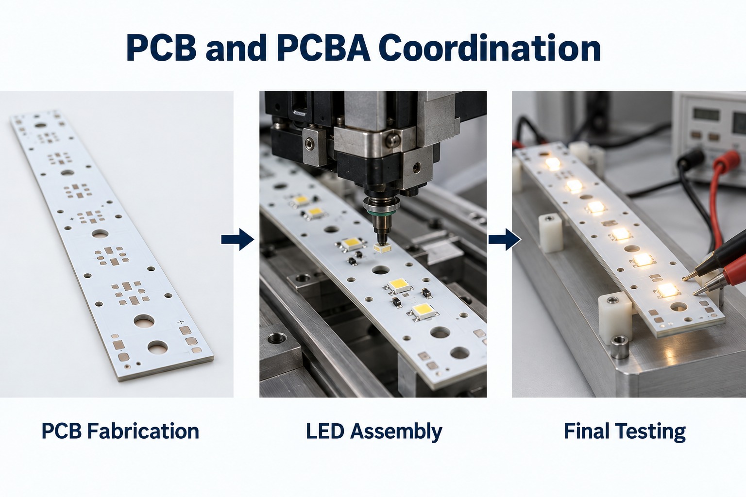
Long aluminum PCB fabrication LED assembly and final testing

PCB and PCBA problems are easier to trace

When one supplier manages both stages, it is easier to identify whether a defect comes from:

  • Bare PCB
  • Solder paste printing
  • LED placement
  • Reflow
  • Components
  • Assembly fixtures

This reduces repeated communication between separate PCB and SMT suppliers.

LED bin and BOM management becomes easier

LED projects often require tight control of:

  • LED bin
  • Color temperature
  • Forward voltage
  • Driver IC
  • Resistors
  • Connectors
  • Approved substitutions

Centralized material control makes batch traceability simpler.

SMT parameters can match the MCPCB

Aluminum PCBs have different thermal behavior from FR4 boards. Assembly settings should therefore be matched to the real MCPCB structure.

Important parameters include:

  • Preheating
  • Reflow profile
  • Solder paste behavior
  • Fixture support
  • Thermal balance

DFM and DFA can be reviewed together

The same engineering team can review:

  • PCB layout
  • Panelization
  • LED footprint
  • Component spacing
  • Fiducials
  • Tooling holes
  • Test points
  • Assembly direction

This reduces the risk of designing a board that is easy to fabricate but difficult to assemble.

Responsibility is clearer

Fewer manufacturing interfaces mean fewer delays when a problem needs to be investigated.

Prototype-to-volume transfer is smoother

Engineering changes, inspection findings, and process settings can remain within the same manufacturing system as production moves through:

  • Prototype
  • Pilot run
  • Volume production

At EBest Circuit, we support both MCPCB fabrication and PCB assembly, allowing our engineering team to review bare-board and assembly requirements together before production.

What Should Buyers Ask an Aluminum PCB Manufacturer?

Buyers should ask questions that confirm whether the supplier can control the actual board design and production process. Ask the supplier to review the actual aluminum PCB design.

A practical checklist includes:

  • What is your maximum board length?
  • What is your maximum panel size?
  • What aluminum thicknesses are available?
  • What copper weights can you produce?
  • What dielectric options do you offer?
  • What thermal conductivity options are available?
  • Can you provide thermal resistance data?
  • What breakdown voltage can the dielectric support?
  • What surface finishes are available?
  • What flatness can you control?
  • What IPC class can you support?
  • Do you use AOI?
  • How is electrical testing performed?
  • How are long boards dimensionally inspected?
  • What are the prototype and production lead times?
  • What is the MOQ?
  • Are tooling or NRE charges required?
  • Can you provide PCB assembly?
  • How is lot traceability managed?
  • What quality certifications do you hold?

For long narrow boards, buyers should also ask how the supplier handles the PCB during routing, inspection, storage, and packaging.

These steps have a direct impact on final flatness and mechanical condition.

What Files Should You Send for an Aluminum PCB Quote?

For an accurate aluminum PCB quotation, send enough information for the manufacturer to review dimensions, materials, tolerances, and production requirements.

For bare aluminum PCB projects:

  • Gerber files
  • Fabrication drawing
  • Board dimensions
  • Board thickness
  • Copper weight
  • Aluminum specification
  • Dielectric requirement
  • Thermal conductivity
  • Surface finish
  • Quantity
  • Annual demand, if available
  • Flatness requirement
  • Critical tolerances
  • Electrical test requirements

For PCB assembly projects:

  • BOM
  • Pick-and-place file
  • Assembly drawing
  • Gerber files
  • LED bin requirements
  • Approved component manufacturers
  • Substitution rules
  • Test requirements
  • Prototype quantity
  • Production quantity
  • Forecast, if available

For LED lighting projects, LED bin requirements should be clearly defined when color temperature, brightness, or forward-voltage matching is important.

FAQ About Long Aluminum PCBs

Can a long aluminum PCB replace a flexible LED strip? Only where the installation accepts a rigid board. A conventional aluminum PCB cannot follow curves like a flexible strip, so the mechanical layout and mounting method may need to change.

Is white solder mask an electrical insulation layer? No. In the basic metal-core stackup, the specified dielectric isolates the copper circuit from the aluminum base. White solder mask covers the circuit surface and must not be treated as a replacement for that insulation.

Can LEDs and their driver use the same aluminum board? They can share a board if routing, insulation, thermal conditions and assembly access permit. A separate FR-4 driver board may be more practical when the driver requires more complex routing.

Does increasing aluminum thickness always solve overheating? No. It can change heat spreading and stiffness, but it does not remove resistance in the dielectric or a poor board-to-heatsink interface. Check the complete thermal path before changing thickness.

Can a long board be divided into shorter modules? Yes, if the optical and electrical design allows it. The trade-off is easier handling against additional interconnections, mechanical joints and possible gaps in the light pattern.

Why Choose EBest Circuit for Long Aluminum PCB and PCBA Projects?

EBest Circuit combines aluminum PCB fabrication, component sourcing, and PCB assembly, allowing the bare board, LEDs, BOM, assembly process, and inspection requirements to be reviewed as one project.

For long and narrow LED boards, our engineering review can cover:

  • Board length, width, and thickness
  • Aluminum and dielectric selection
  • Copper weight and circuit layout
  • Flatness and dimensional requirements
  • Panelization and routing
  • LED bin and BOM control
  • SMT process requirements
  • AOI and electrical testing
  • PCBA inspection and functional testing
  • Packaging for long boards

We treat long-board requirements separately from standard MCPCB production because equipment size, handling, flatness, and dimensional control can become more critical as board length increases.

If your project involves a long aluminum PCB, LED MCPCB, FR4 control board, or complete PCB assembly, send your Gerber files, BOM, drawings, quantities, and manufacturing requirements to sales@bestpcbs.com. If assembly is required, include the BOM, pick-and-place file, and test requirements as well.

Our engineering team can review manufacturability, thermal requirements, assembly conditions, and production planning before quotation.

You may also like

PCB Aluminium Substrate, Aluminum PCB Board for LED
Thursday, April 17th, 2025

When it comes to reliable and advanced PCB solutions, EBest Circuit (Best Technology) leads the way. With more than 18 years in the industry, we provide custom circuit board manufacturing for global clients. From prototype to volume production, we help you build better products with very good heat dissipation and military-grade quality. Our strength lies in metal-based PCBs, especially pcb aluminium substrates. These are widely used in LED, automotive, telecom, and power industries. With precision equipment and a strict quality system, we ensure high-performance boards that meet your needs.

What Is a PCB Aluminium Substrate?

A PCB aluminium substrate is a type of metal-based printed circuit board. (MCPCB) It uses aluminum as its base material instead of traditional FR4. This base supports layers of dielectric, and copper circuits. Aluminum PCBs offer strong heat dissipation and structural support compared with normal rigid PCB. The aluminum base acts as a heat sink. This makes the substrate ideal for high-power or thermally sensitive applications. In simple terms, it’s a PCB built on aluminum rather than fiberglass.

Performance of Aluminium Substrate PCB in LED

Aluminum substrate PCBs are the backbone of today’s LED lighting systems. Their ability to manage heat is the most critical factor. When LEDs operate, they generate a lot of heat at the junction point. If that heat isn’t removed quickly, the LED’s brightness fades, and its lifespan shortens. Using an aluminum board for LED, we can get these benefits:

  • Efficient heat dissipation: The aluminum metal base acts as a built-in heat sink, pulling heat away from the LED source and spreading it across the board.
  • Improved reliability: By reducing thermal stress, the board helps extend the lifespan of each LED component. That means longer-lasting light and less need for replacement.
  • Stable light output: Overheating causes LEDs to dim. Aluminum PCBs maintain the thermal balance so that brightness stays consistent. Whether it’s a street lamp or a small indoor fixture, aluminum PCBs deliver stable operation.
  • Compact design: Since aluminum boards manage heat on their own, there’s no need for bulky external cooling systems.
  • Cost-effective: Although slightly more expensive than FR4, their longer lifespan and lower maintenance needs make them a better investment for lighting manufacturers.

6061 vs. 5052 vs. 1060 Aluminum Substrate

In the aluminum PCB manufacturing, the common aluminium substrates that manufacturers always use are 6061 aluminum substrate, 5052 aluminum substrate and 1060 substrate. All of them are aluminum allay, but the compositions and purity are different, so that the performance different too.

5052 aluminum sheet belongs to Al-Mg alloy, the main alloying element is magnesium, which has a content of 2.2% ~ 2.8%. In addition, it also contains a small amount of chromium (0.15%-0.35%) and other elements. The addition of which is intended to improve the strength and corrosion resistance of the alloy. 6061 aluminum sheet is Al-Mg-Si alloy, in addition to magnesium (0.8%-1.2%) and silicon (0.4%-0.8%) as the main alloying elements, copper (0.15%-0.4%) and zinc (less than 0.25%) are also added. 1060 aluminum material belongs to pure aluminum sheet, with an aluminum content of more than 99.6%, and almost no other alloying elements. Different alloy components form the basis of the different performances of these aluminum substrates. Below is a table comparison show the differences between each of them:

Property6061 Aluminum5052 Aluminum1060 Aluminum
CompositionMagnesium & silicon alloyMagnesium alloyPure aluminum (≄99.6%)
Thermal ConductivityModerate (150 W/m·K)High (160 W/m·K)Very high (≈237 W/m·K)
Strength of Extension290MPa215MPaLow
Hardness95HB65HB30HB
Elongation10-18%12-25%5%
FormabilityLowHighHigh
Corrosion ResistanceGoodExcellentGood
Common UsesStructural parts, high-load PCBsLED lights, flexible designsHigh heat-dissipation PCBs
CostHigherMediumLower
(6061 vs. 5052 vs. 1060 Aluminum Substrate)

So how to choose the suitable substrate for your aluminum PCB board? Follow this rule:

  • Choose 1060 if your project needs maximum thermal conductivity.
  • Choose 5052 if flexibility and corrosion resistance are more important.
  • Choose 6061 if you need strength and rigidity for heavy-duty PCBs.

What Is the Dielectric Layer of Aluminum PCB?

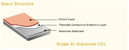
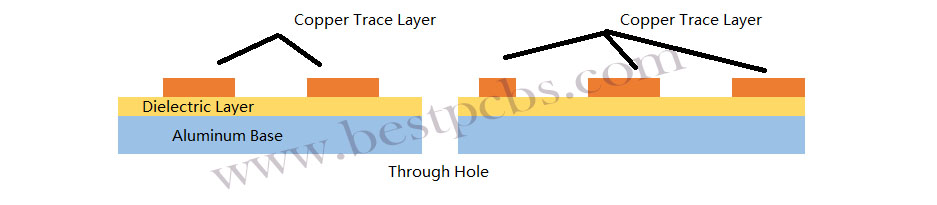
Aluminum substrate is generally composed of three layers: circuit layer (copper foil), dielectric layer and metal base. The dielectric layer is located between the circuit layer and the metal base layer, which acts as insulation and heat conduction. It is a polymer filled with high thermal conductivity and high insulation ceramic powder, make it is an ideal material with non-conductive but heat-conductive.

single sided PCB aluminium substrate structure

This dielectric layer has good heat conduction properties (thermal conductivity up to 3.0W/m-K), it is the key to thermal performance. It allows heat to pass from the copper to the aluminum while keeping them electrically isolated. The dielectric must have low thermal resistance and high breakdown voltage. Materials used often include ceramic-filled epoxy or polyimide. These support thermal conductivity while maintaining safety.

What Is the Difference Between FR4 and Aluminum PCB?

FR4 PCBs use fiberglass as a base. They are cheaper and more common. But they are poor at dissipating heat. They also deform more under thermal stress. Aluminum PCBs, on the other hand, handle heat much better. The aluminum pcb thermal conductivity is usually between 1.0 to 3.0 W/m·K. In contrast, FR4 is less than 0.3 W/m·K. That means aluminum PCBs can move heat away much faster. Here we listing the main differences between two of them:

FeatureFR4 PCBAluminum PCB
Base MaterialFiberglass-reinforced epoxyAluminum metal
Thermal Conductivity≈0.3 W/m·K1–3 W/m·K
Heat DissipationPoorExcellent
Mechanical StrengthModerateHigh
EMI ShieldingWeakStrong
Cost (under the same design complexity situation)LowerSlightly higher
Use CasesConsumer electronics, PCsMainly used in led lights, automotive, power modules
Thickness Options0.10mm, 0.12mm, 0.15mm, 0.20mm, 0.25mm, 0.30mm, 0.40mm, 0.50mm, 0.60mm, 0.80mm, 1.0 mm, 1.2 mm,  1.6mm, >=2.0 mm0.30mm, 0.40mm, 0.50mm, 0.60mm, 0.80mm, 1.0 mm, 1.2 mm, 1.6mm, 2.0 mm, 2.4mm, 3.0mm (exclude copper)
WeightMuch lighterHeavier but lighter than copper pcb
Environment ToleranceLower heat resistanceWithstands high temperatures

How Do You Make Aluminium PCB?

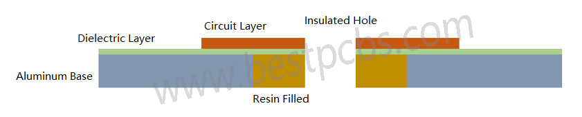
The manufacturing process of aluminum PCB is almost the same as normal FR4 PCB, except the lamination process of dielectric layer, aluminum and copper. This also is the biggest manufacturing difficult that faced by manufacturers, especially for multi-layer aluminum PCB. For the single & double sided aluminum PCB, the aluminum substrate we purchased from the manufacturers are laminated with dielectric, so we do not need to laminate again. In addition to this, the manufacturing process of aluminum PCB with insulated hole and without insulated hole are different.

  • Single-sided Aluminum PCB without insulated hole:

Cutting raw material (substrate laminated with dielectric layer) — Circuit layer generation (D-E-S) — Solder Mask – Silkscreen — Surface Treatment — Stripping — Drill Holes — Outline (V-cut – Routing – Die Punching) — QC — Package & Delivery

Single-sided Aluminum PCB without insulated hole
  • Single-sided Aluminum PCB with insulated hole:

Cutting raw material (substrate without laminated with dielectric layer) — Drill larger holes — Filled resin with holes — Lamination (dielectric layer + copper + aluminum base) — Circuit layer generation (D-E-S) — Solder Mask – Silkscreen — Surface Treatment — Stripping — Drill Holes — Outline (V-cut – Routing – Die Punching) — QC — Package & Delivery

Single-sided Aluminum PCB with insulated hole

Manufacturing Difficulties of Aluminum PCBs

Working with aluminum is not the same as working with FR4. It brings challenges, especially for a professional aluminum PCB manufacturer.

1. Mechanical Processing

Drilling holes on aluminum PCBs is possible, but the inner walls and board edges must be completely free of burrs. Even a slight burr can cause the board to fail the high-voltage test. Milling the outline is also quite difficult. The milling cutter used for FR4 PCB board has a relatively low hardness, while the milling cutter used for aluminum substrate has a high hardness. During the processing, the milling cutter for fiberglass board production has a high speed, while the milling cutter for aluminum substrate production has a speed at least 2/3 slower. As an alternative, punching with high-precision dies is often used—but die making requires exceptional skill, making this one of the main challenges in aluminum PCB manufacturing.

After punching, the edges must be clean and smooth, without any burrs or damage to the solder mask along the edges. Most factories use compound dies. Holes are punched from the circuit side, and the outline is punched from the aluminum side. This requires specific techniques, such as upward shearing and downward pulling during punching. Even after punching, the board’s warpage must be strictly controlled and should remain under 0.5%.

2. Protecting the Aluminum Surface During Processing

The aluminum base must remain completely free of scratches throughout the entire production process. Any direct contact with hands or chemicals can cause surface discoloration or oxidation, which are absolutely unacceptable. In many cases, re-polishing the aluminum surface is not allowed by customers. So, avoiding even the slightest damage to the aluminum layer is another major difficulty in the production process.

Some manufacturers use surface passivation treatments, while others apply protective films before and after hot air solder leveling (HASL). There are countless tricks and methods used to keep the surface clean—every factory has its own unique way of doing it.

3. High-Voltage Testing Requirements

For telecom power supply boards, 100% high-voltage testing is often mandatory. Some clients require DC testing, while others specify AC, typically at 1500V or 1600V for durations of 5 to 10 seconds. Every single board must pass this test.

Even the smallest contamination on the surface, burrs on holes or edges, jagged traces, or damage to the insulation layer can lead to arcing, leakage, or dielectric breakdown during testing. Boards that show signs of delamination or bubbling during the test are automatically rejected.

Despite these, trusted manufacturers like EBest Circuit (Best Technology) handle it well. Our experience helps solve such problems early in the process.

How Much Does Aluminum PCB Cost?

Many factors influence the pcb aluminium substrate price. These include:

  • Aluminum grade (6061, 5052, or 1060)
  • Thickness of copper and base layer
  • Board size and layer count
  • Surface finish type
  • Quantity ordered
  • Special design features (e.g., thermal vias, contours)

In general, aluminum PCBs cost more than FR4 boards. But for heat-sensitive designs, the added cost pays off in reliability.

For instance, a basic one-layer aluminum PCB may start from $1.0–$5.0 per unit in bulk. Complex designs with multi-layers or special finishes can go higher. EBest Circuit (Best Technology) offer competitive pricing without cutting corners. We also provide quick prototypes aluminium PCB substrate and full-scale production to meet your timeline and budget.

If you are interested in PCB aluminium substrate or aluminum PCB manufacturing, contact us today to learn more about our aluminum PCB board solutions. Let’s build something great together—strong, reliable, and ready for tomorrow’s tech.

You may also like