PCB manufacturing PCB manufacturing
Home > Blog

USB 2.0

USB 2.0 Common Mode Choke: Check EMI and the Eye
Tuesday, November 10th, 2026

Add a USB 2.0 common mode choke only if the evidence points to noise on the data pair and the part improves emissions without consuming too much High-Speed signal margin. Compare a populated choke and a qualified bypass under the same test conditions. If emissions improve but the eye fails, the choke is not ready for production.
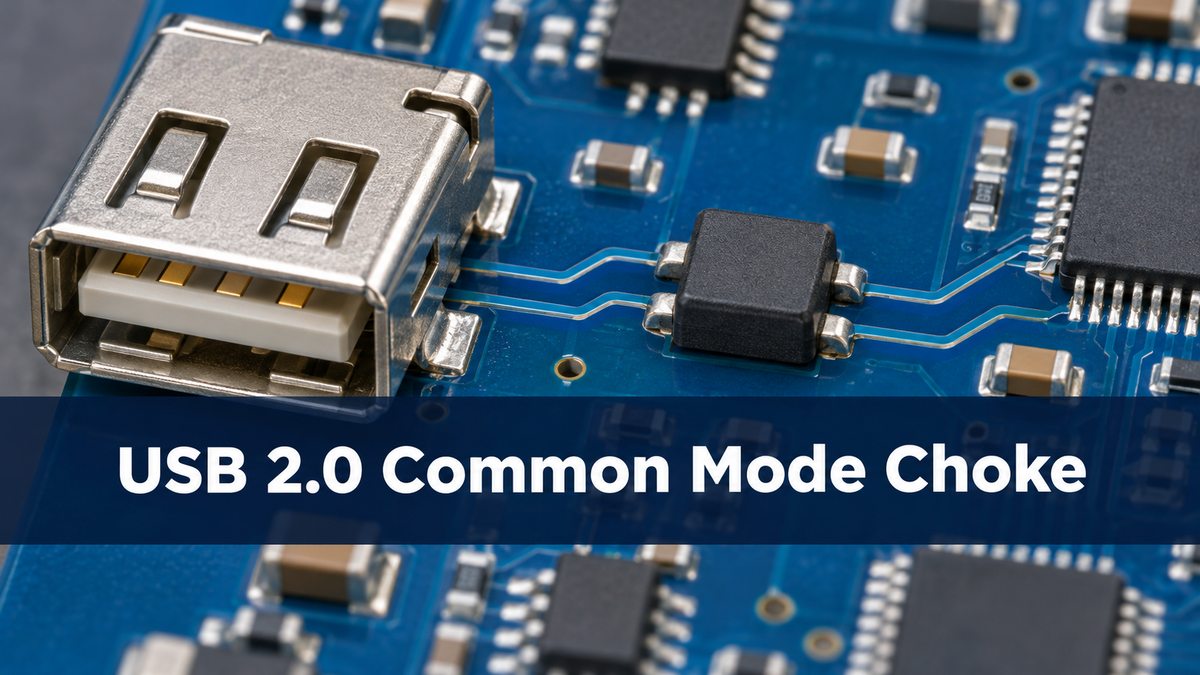
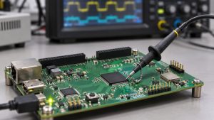
USB connector and a nearby small component on a circuit board
Illustrative rendering of a USB connector region, not a validated layout.

usb 2.0 common mode choke

A two-line choke uses coupled windings in series with D+ and D−. Ideally, signals flowing in opposite directions see little added impedance, while noise flowing in the same direction on both lines sees more. Real devices also have parasitics and differential loss. The part does not replace ESD protection, nor does it establish the pair’s PCB impedance.

usb common mode noise

First decide which path is carrying the noise. In a hypothetical USB service port, a radiated peak appears only when the cable is attached. That makes the cable a useful clue, not proof that D+ and D− are the source. Compare activity with controlled traffic and examine the shield and power paths. A data-pair choke will not necessarily address noise predominantly carried on VBUS or the shield.

common mode choke impedance

Read common-mode impedance versus frequency, then check the differential transmission and balance data. For example, Murata lists 90 Ω ±25% at 100 MHz for DLW21SN900SQ2 under its specified test conditions. That number is common-mode impedance at one frequency; it is not a differential routing target, bandwidth, or guarantee of attenuation in the product.

Parameter What to compare
Common-mode impedance, Ω Curve around the suspect frequency
Differential loss, dB Curve across the relevant signal band
DC resistance, Ω Maximum and balance between lines
Package and pinout Channel mapping and footprint

usb common mode choke selection

Prefer a device with relevant mixed-mode data and enough signal margin in the implemented layout. A higher catalog impedance at one frequency can still be the wrong choice if loss or imbalance increases. Keep a qualified bypass option where practical, but do not assume a jumper footprint is electrically invisible. Compare the routing geometry and inspect the built boards.

usb common mode choke placement

Follow the actual PHY and protection guidance. TI’s TUSB121x example places the choke close to the receptacle, on the PHY side of the ESD devices. That is a named implementation, not a universal placement rule. Preserve the shortest protection path from the connector and review the two parts together. See the USB 2.0 ESD placement guide for the separate transient-path check.

usb differential pair routing

Keep the pair symmetric through the connector, protector, choke pads and layer changes. If you provide bypass footprints, avoid an unused branch hanging from only one line. A common-mode problem can be aggravated by imbalance in the routing, so compare both the footprint and the continuous reference before asking the choke to hide a layout problem.

usb 2.0 radiated emissions

Compare the two builds using the same cable, orientation, equipment arrangement and representative activity. In the example, suppose the suspect peak falls by 4 dB after fitting the choke. That is an illustrative comparison, not a lab result or a compliance claim. Confirm the absolute result against the project’s applicable limit and check repeatability before crediting the component.

Outcome Decision
Emissions and eye both meet limits Confirm repeatability before release
Emissions improve but eye fails Reject; revisit part or routing
Eye passes but emissions do not improve Trace the actual noise path

usb 2.0 eye diagram

Verify the 480 Mbit/s High-Speed eye in the applicable test mode and fixture, not just enumeration or a short file transfer. A tight result with one cable is a reason to repeat the approved test under the required conditions, not to declare the change safe. For the controller example, release the choke only after the emissions result and the applicable USB electrical result both meet the agreed criteria.
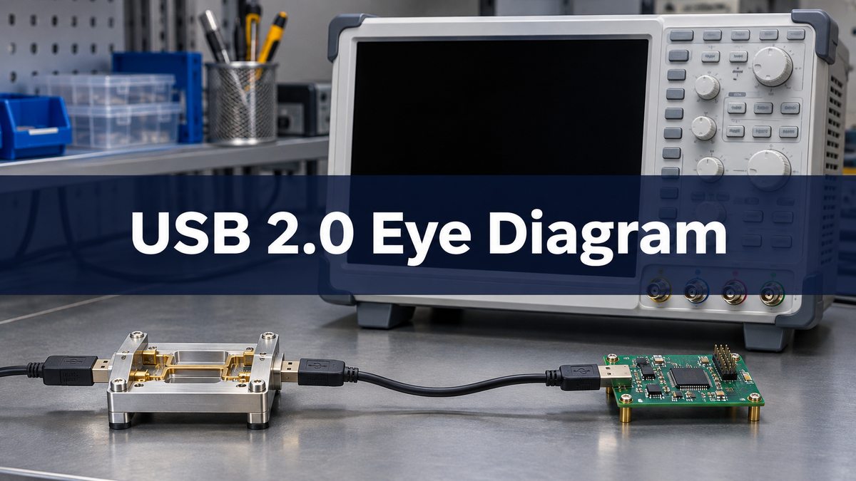
USB test fixture and cable on a bench beside an oscilloscope
Illustrative rendering of a test bench. Use the specified USB test fixture and real capture for acceptance.

FAQ

Is the choke needed on every High-Speed port?

No. Use evidence from the intended system and the device guidance. A correctly working port need not add unnecessary loading.

Can I select a choke using only its 100 MHz impedance?

No. Compare frequency-dependent common-mode behavior, differential loss and the actual board measurements.

Can a bypass trial leave the pads empty?

Not if that opens the signal lines. Use the qualified bypass connection for the designed footprint.

Does enumeration show the High-Speed eye passes?

No. Enumeration is a functional observation. Use the applicable electrical test for the eye and signal limits.

Will the choke fix ESD resets?

Not by default. Inspect the discharge path and protection design separately, then verify the system’s ESD behavior.

Should I compare different cables in the first A/B test?

Keep the cable fixed for the first comparison. Test additional required cables separately to verify system robustness.

Can a data-pair choke fix VBUS noise?

Only if the coupling path involves the data pair and the change is shown to help. Inspect the power path if that is the dominant source.

Does a lower measured peak mean the product is compliant?

No. Check the applicable limit, modes and repeatability. A relative improvement and a compliance result are different claims.

Sources

TI TUSB121x board guidelines; TDK: USB 2.0 EMC practice; Murata DLW21SN specifications.

Project Review

For a Best Technology fabrication discussion, send the stackup, D+/D− geometry, connector footprint and choke or bypass options to sales@bestpcbs.com.
You may also like

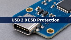
USB 2.0 ESD Protection: Where to Put the Diode on a PCB
Tuesday, November 10th, 2026

For a USB 2.0 High-Speed port, start with a low-capacitance ESD diode close to the connector. Route D+ and D− past the protection pads without long branches, and give the diode a short return into the intended reference. Verify both USB signal quality and system ESD behavior: a board can enumerate and still reset during a discharge, or survive a strike and still fail the High-Speed eye test.

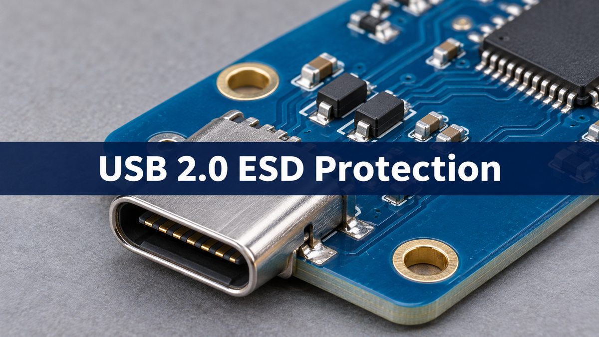
USB-C receptacle with small protection components at the edge of an assembled PCB
Illustrative rendering of a connector area, not a reference layout or a test result.

usb 2.0 esd protection

Protect the path from the exposed connector to the USB transceiver. When a transient exceeds the diode’s operating region, the diode conducts current into its return path instead of allowing all of the pulse to continue toward the transceiver. During normal signaling the device should remain off, but its capacitance still loads the pair. The goal is to minimize both the discharge loop and the disturbance seen by the data signals.

usb esd protection circuit

Draw two paths before choosing the footprint: the D+/D− signal path from the connector to the PHY, and the transient current path from each exposed data line through its protector into the designated return. The reference circuit for the selected part determines which pin is the return and whether the device uses a rail reference. A D+/D− protector does not establish protection for VBUS, CC or SuperSpeed pairs. For the rest of the interface, see the USB-C PCB design guide.

usb 2.0 esd protection diode

Choose a device against the PHY and connector requirements, not the largest advertised discharge rating. For example, TI’s USB application note lists ESD122 as a dual-channel D+/D− option with a 3.6 V reverse working voltage and 0.2 pF listed capacitance. Those figures belong to that device; use its current datasheet for test conditions and limits, then check actual layout and system behavior.

Parameter Decision check
Working voltage, V Check against normal line voltage
Line capacitance, pF Use stated test conditions and PHY budget
Clamping voltage, V Compare only at matching pulse conditions
Channel and package Confirm pin map and a routable return
Discharge rating, kV Check method; verify on the complete product

esd diode placement

Put the protector at the first practical point after the connector and keep both the connection to the data pads and the discharge return short. A component can look close in the placement view while its ground trace makes a long trip around a cutout. Check the copper layers and return vias, not just the component outline. Do not route the unprotected connector segment alongside sensitive circuitry if it can be avoided.

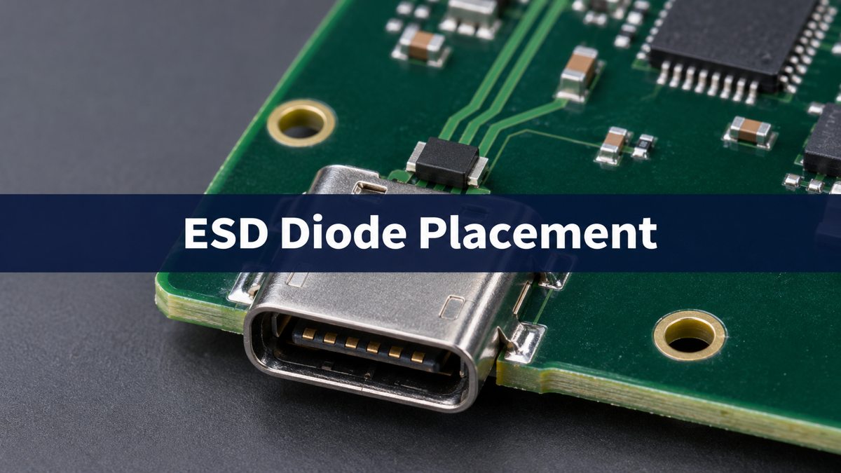
Close-up of a board-edge USB-C receptacle and a nearby black leadless component
Illustrative rendering. Verify the chosen footprint and discharge return on the actual PCB.

usb esd protection layout

Prefer flow-through routing when the part and footprint allow the data traces to pass directly through the protection-pad area. The diode remains a shunt element; the name describes the routing, not a series electrical connection. A short branch can be an alternative if the pinout forces it and the implemented design passes both signal and system ESD tests.

Routing option Use and trade-off
Flow-through First choice when pad map and return align
Very short branch Possible when constrained; measure the result
Long branch or remote clamp Revise: extra stub and transient loop

usb differential pair routing

Keep the two data paths physically similar through the connector, protector and first layer transition. Review reference continuity and avoid adding a long test stub to only one member of the pair. In a hypothetical compact service-port board that resets during cable-side testing, first inspect the discharge route and nearby reset or power circuits. If the same board also shows poor High-Speed signaling, check the diode capacitance, pad discontinuities and pair asymmetry before choosing a different clamp rating.

usb 2.0 differential impedance

The usual High-Speed differential routing target is 90 Ω nominal; confirm the tolerance and stackup requirements for the design. A calculated trace width covers the uniform section, not the pad and via transitions. Review those transitions separately, and include the protection device’s capacitance. The relevant data rate is 480 Mbit/s in High-Speed mode, but edge behavior is not determined by the bit rate alone.

usb 2.0 eye diagram

After a layout revision, verify the applicable High-Speed electrical test separately from the system ESD test. Use the specified USB test mode and fixture for the electrical test; for ESD, record the strike point, polarity, operating mode and allowed recovery behavior under the product test plan. Monitor real data traffic, resets and re-enumeration. Release only when the electrical result meets its applicable limits and the product meets its own ESD performance criterion. Successful charging or idle enumeration is not a substitute for either check.

FAQ

Can one array cover VBUS and the two data lines?

Some products can, but check the channel specifications and routing. VBUS operating voltage and exposure may differ from the data lines.

Is a larger TVS diode always a safer upgrade?

No. A larger part may add capacitance or create a worse return path. Check clamp behavior under comparable pulse conditions as well as link quality.

Can I place the protector on the bottom side?

Sometimes. Compare the complete path including signal vias, return vias and loop geometry. Verify the actual implementation rather than judging it by distance in a top view.

Should the common-mode choke go before the diode?

In TI’s TUSB121x example it follows the ESD protection. Confirm the sequence in the PHY and protector references and qualify it on the actual board.

Does a connector shield replace the data-line protector?

No. Shield bonding and signal-line protection address different paths. Follow the intended chassis and board grounding architecture rather than assuming they are interchangeable.

Why might the port restart even though no diode failed?

A transient can disturb the supply, reset path or reference. Capture the symptom and investigate the current route and nearby sensitive circuits before replacing the diode. The PCB ground bounce guide explains how a changing local reference can show up in a measurement.

Is a device-level rating proof of system compliance?

No. The assembled product adds connector, enclosure, layout and grounding variables. Verify it with the applicable system test and performance criteria.

Does this placement apply unchanged to USB SuperSpeed?

No. Check the separate transmit and receive paths, channel budget and AC coupling architecture. This guide addresses USB 2.0 D+ and D−.

Sources

Texas Instruments: ESD and Surge Protection for USB Interfaces; Texas Instruments: TUSB121x board guidelines; Nexperia: ESD protection for USB 2.0 interfaces.

Project Review

For a PCB fabrication discussion, send Best Technology the proposed stackup, pair geometry and connector-to-protector region at sales@bestpcbs.com.

You may also like