Glass weave skew is a difference in arrival time between signals caused by the local glass-and-resin structure of a PCB laminate. Two differential traces can have equal geometric length yet different propagation delay if they sample different dielectric environments. Length matching is therefore necessary for many interfaces but does not, by itself, prove matched electrical delay.
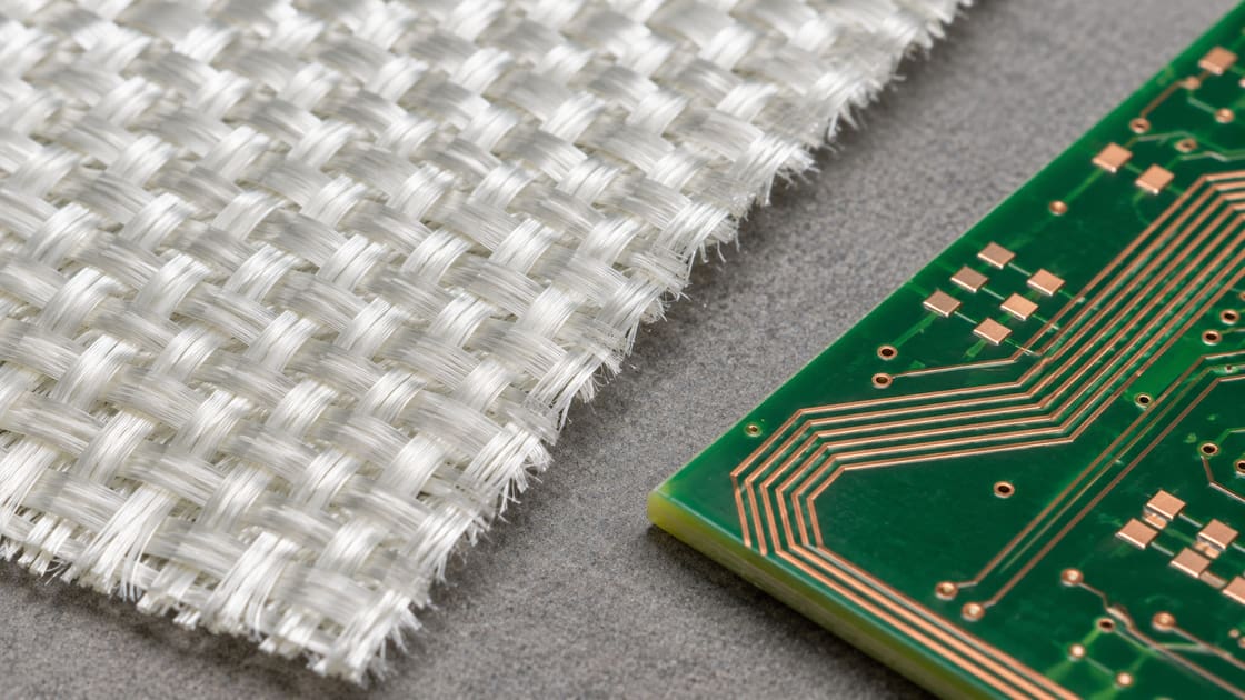
This guide explains the mechanism, compares mitigation choices and shows how to include weave effects in a timing review. It focuses on differential-pair delay, not on changing a laminate merely because its published bulk dielectric constant is lower.
What creates glass weave skew?
A woven reinforcement has glass-rich yarn regions and more resin-rich spaces between them. A trace following one region for a long distance can experience a different effective dielectric environment from its partner. Effective permittivity is the combined field-dependent property seen by the transmission line, not simply the bulk value of one ingredient.
The effect depends on the material construction and how the traces align with it. A controlled-impedance stackup describes the nominal line, but small local differences can remain important when the available timing margin is narrow.
What parameters belong in the timing review?
Start with delay and margin at a defined reference plane. Geometric dimensions are inputs; arrival-time difference is the quantity the receiver ultimately sees.
| Input | Unit | Purpose |
| Pair delay difference | ps | Compare with allowed budget |
| Coupled route length | mm | Identify long exposed regions |
| Copper length mismatch | mm | Separate geometry contribution |
| Glass construction | Style and treatment | Identify actual reinforcement |
| Route to weave angle | Degrees | Assess repeated alignment |
| Material variant | Full construction | Avoid generic FR-4 assumptions |
Do not borrow a skew limit from an unrelated interface. Use the applicable device and link requirements, then allocate margin among the PCB, package, connector and other parts of the path.
Equal length vs equal electrical delay
Equal length removes one source of mismatch but not all of them. In a simplified uniform transmission line, delay per unit length scales approximately with the square root of effective permittivity. A different local effective value can therefore change travel time along two equally long routes.
That approximation is a teaching model. It does not predict a woven laminate’s exact local behavior, because real fields span several materials and the construction is not uniform along the path. Use it to understand why a ruler is not a complete timing instrument.
A worked example of the remaining margin
Suppose a hypothetical link allocates 8 ps to PCB pair mismatch. A simulation or representative measurement already attributes 3 ps to the routed geometry. Only 5 ps remains within that allocation for other PCB contributions under the chosen budgeting method.
You cannot conclude that the weave contribution is zero because the layout tool reports equal length. Also, do not add independent estimates without checking whether they describe the same effect twice. This example is budget arithmetic, not a universal interface limit.
Compare routing and material mitigation choices
Choose a method that addresses how both traces sample the reinforcement, then evaluate its effect on the rest of the layout.
| Option | Intended benefit | Trade-off to verify |
| Route at an angle | Cross multiple yarn regions | Extra length and routing space |
| Rotate panel image | Change trace-to-weave alignment | Panel use and fabrication agreement |
| Use spread-glass construction | More uniform local structure | Exact material and stackup availability |
| Qualified weave-aware stackup | Known construction and evidence | Substitution control and cost |
No option guarantees zero skew. The useful question is whether the chosen construction and geometry leave sufficient margin in the actual link.
Why route angle must be relative to the weave
An angle relative to the board edge matters only if the reinforcement orientation is known relative to that edge. A pair drawn diagonally can still align poorly with a rotated material. State the intended relationship in the fabrication discussion rather than relying on the appearance of the layout.
Texas Instruments’ high-speed layout guidance discusses routing and image-rotation approaches. Treat those examples as mitigation guidance; confirm the appropriate construction and geometry for your interface.
What spread glass changes and what it does not
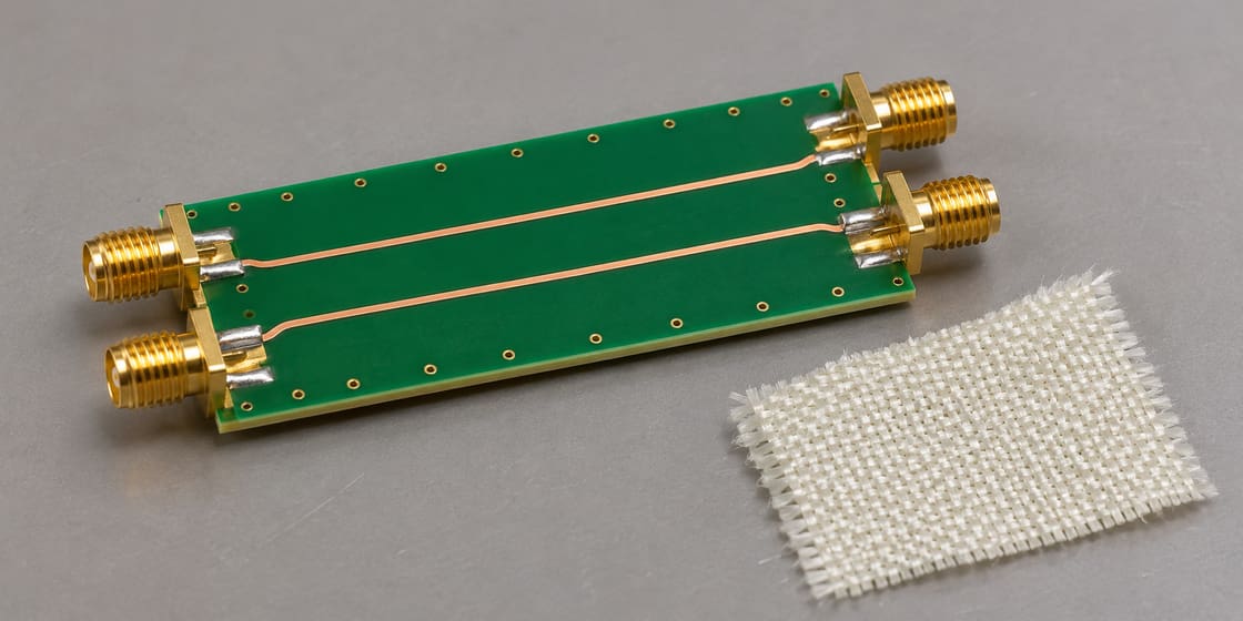
Spread-glass reinforcement distributes yarns more uniformly than an open, concentrated weave pattern. That can reduce local differences sampled by nearby traces. The designation must still identify a real supplied material construction; “spread glass” is not a complete stackup specification.
It does not remove connector asymmetry, via mismatch or an unsuitable return path. Keep each mechanism distinct during review so a material upgrade is not used to avoid correcting an ordinary layout problem.
Why nominal Dk is not a weave-skew specification
A data-sheet dielectric constant summarizes a material under a stated method and condition. It does not directly state how much two adjacent traces will differ over a particular route. Two constructions with similar nominal Dk can still distribute their reinforcement differently.
Ask for the actual glass styles, resin system and construction relevant to the routing layer. If the supplier proposes a substitute, compare that construction and its evidence rather than approving it solely on the nearest bulk Dk number.
Avoid fixing the wrong kind of mismatch
A connector launch, unequal via transitions or different reference conditions can create delay or mode-conversion problems that resemble a pair imbalance. Review those discontinuities before attributing a measured difference entirely to weave.
The BestPCBs SCD21 mode-conversion guide addresses a related measurement result. Mode conversion can be evidence of imbalance, but it does not identify glass weave as the cause on its own.
Use a coupon that represents the real routing
A useful comparison keeps the stackup, routing layer, geometry, length and reference method under control. Include the proposed orientation or construction change. Keep launch and fixture contributions consistent so their difference is not mistaken for a laminate improvement.
Sampling matters because trace placement relative to the weave can vary. A single favorable coupon is not proof that every route or panel position will behave identically. Agree the evaluation plan with the fabricator and signal-integrity team.
Keep the mitigation in the released fabrication package
Record the approved laminate construction and any agreed image rotation or orientation requirement. Make substitution review explicit. Otherwise, a repeat order can preserve the copper artwork but change the reinforcement arrangement behind the original timing evidence.
Separate a requested process from a verified outcome. A drawing note asking for a particular construction is not a measurement report. Retain both the material identity and the relevant coupon or link evidence with the design revision.
Decide whether the link actually needs a change
A weave-aware review is most useful when the route length, signaling requirements and remaining margin make the effect significant. Do not add routing complexity or an expensive material solely because the mechanism exists. Compare the proposed change against the timing budget and practical verification evidence.
For a Best Technology stackup review, send the interface requirements, layer construction, long pair routes and timing evidence to sales@bestpcbs.com. Ask for construction and orientation confirmation before releasing a material-dependent mitigation.
FAQ
Can glass weave matter when a pair is perfectly length matched?
Yes. Matching copper length addresses geometric mismatch, while local dielectric variation can change delay per unit length. The significance depends on the route and available timing margin. Keep both effects in the review and use representative construction evidence rather than assigning a universal skew value.
Is there a single maximum length below which weave never matters?
No universal cutoff applies to every interface and laminate. Sensitivity depends on route geometry, construction, alignment and the allowed delay difference. A short low-demand link may have ample margin, while a stricter design needs a quantified review. Use the actual budget rather than a general length rule.
Does routing at 45 degrees always solve the problem?
No. The relevant angle is relative to the reinforcement, not just the board outline, and the actual construction still matters. An angled route can help both traces sample different regions, but it also changes route length and space. Verify the resulting link rather than assuming a particular angle guarantees success.
Can I compensate weave skew with a fixed length adjustment?
Be cautious if the underlying local variation is not repeatable across builds. A fixed compensation can correct one measured specimen while worsening another. Distinguish deterministic geometry from material variation and confirm the behavior across the agreed sample set before applying a production adjustment.
Does lower Dk automatically mean lower weave skew?
No. Bulk permittivity and local uniformity are different properties. A material with a lower published Dk can still have a construction that creates unequal local environments for two traces. Compare the actual reinforcement and route conditions, and keep the test method attached to any numeric material data.
Can I infer glass weave from an impedance report alone?
Not reliably. An impedance report can show whether the measured line meets its stated target, but it does not isolate the cause of pair delay mismatch. Use suitable delay or mixed-mode measurements and a controlled comparison if the investigation needs to distinguish weave from launches or other asymmetry.
Should every high-speed board use spread glass?
No. Select it when the construction and link margin justify the change, and verify availability and substitution control. Other design factors may dominate the link. A stackup decision should balance electrical evidence, routing practicality and manufacturing repeatability rather than treating one reinforcement label as a blanket requirement.
Can a repeat order change skew without changing the artwork?
It can if the material construction, orientation or other relevant conditions change. Even with a controlled construction, local alignment can vary. Preserve the approved stackup and process agreements, review substitutions, and use an appropriate sampling plan when timing performance depends strongly on reinforcement behavior.
You may also like

Tags: Differential Pair, Glass Weave, pcb stackup, Signal Integrity