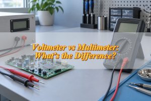
The main difference in voltmeter vs multimeter is what each instrument can measure. A voltmeter measures voltage, while a multimeter typically measures voltage, current, resistance, and continuity. Both can check electrical voltage, but they serve different purposes. If a multimeter already measures voltage, when would you still need a dedicated voltmeter?
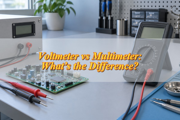
Voltmeter vs Multimeter: What Are the Main Differences?
A voltmeter measures the voltage between two points in a circuit, while a multimeter combines voltage measurement with other electrical testing functions.
| Feature | Voltmeter | Multimeter |
|---|---|---|
| Main function | Voltage measurement | Multiple electrical measurements |
| AC/DC voltage | Depends on model | Usually both |
| Current measurement | Not normally supported | Commonly supported |
| Resistance measurement | Not normally supported | Commonly supported |
| Continuity testing | Not normally supported | Commonly supported |
| Common designs | Handheld or panel-mounted | Handheld or benchtop |
| Typical use | Voltage checks and monitoring | General electrical and PCB testing |
A handheld voltmeter is suitable for portable voltage checks, while a panel voltmeter can display voltage continuously when installed in equipment. A multimeter is more convenient when several electrical measurements are needed.
How Do You Measure Voltage With Each Instrument?
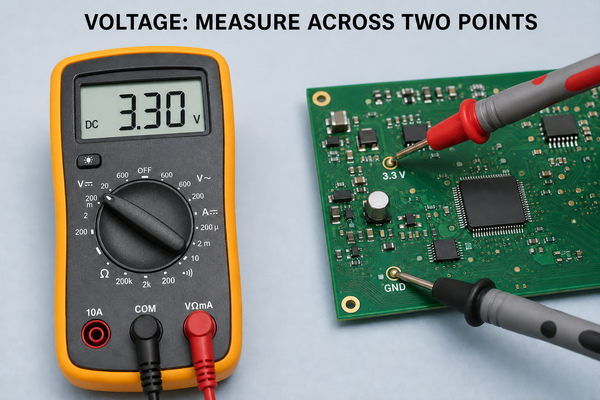
Both instruments measure voltage in parallel across two points without breaking the circuit.
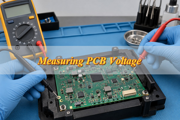
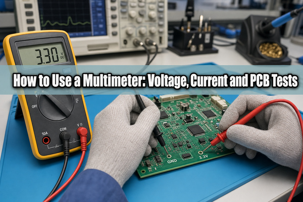
For example, to check a PCB’s DC supply voltage, place the negative probe on the appropriate ground reference and the positive probe on the supply test point.
When using a multimeter:
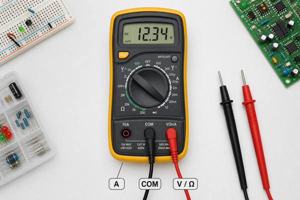
- Connect the leads: Put the black lead in COM and the red lead in the V terminal.
- Select the voltage type: Choose DC voltage (V⎓) or AC voltage (V~).
- Set the range: Choose a suitable measurement range if the meter is not autoranging.
- Take the reading: Connect the probes across the measurement points and read the voltage.
A handheld voltmeter follows the same connection principle. A panel voltmeter may use fixed wiring and require a separate power supply.
Never measure voltage with the red lead connected to a current input. Doing so can cause a short circuit. Before testing, check the meter’s input rating, terminal connections, and safety category where applicable. Use probes rated for the measurement environment.
Can a Multimeter Replace a Voltmeter?
Yes, for most routine voltage checks. The multimeter’s measurement range, AC/DC capability, accuracy, and safety ratings must still meet the application’s requirements.
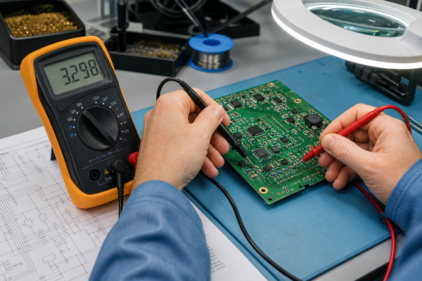
For example, a digital multimeter can measure battery voltage, power-supply outputs, and PCB test points without requiring a separate handheld voltmeter.
However, a handheld multimeter is not always a practical replacement for a panel voltmeter. A panel voltmeter can remain installed in equipment and display voltage continuously, while a handheld multimeter is generally used for measurements taken when needed.
Some benchtop and logging multimeters also support extended monitoring. Replacement therefore depends on installation and operating requirements, not just the ability to measure voltage.
Voltmeter vs Multimeter: Which Is More Accurate?
Neither instrument is inherently more accurate. In a voltmeter vs multimeter comparison, measurement accuracy depends on the specific model and operating conditions.
Three specifications help explain the difference:
- Accuracy: How close the reading is to the actual voltage, within the instrument’s specified limits.
- Resolution: The smallest voltage change the instrument can display.
- Display counts: The number of distinct readings available within a measurement range.
More display digits do not guarantee better accuracy. An instrument may display very small voltage changes while still having a relatively large measurement uncertainty.
To compare two instruments, check the manufacturer’s accuracy specifications for the voltage range you intend to use. Also consider operating temperature and input impedance, especially when measuring high-impedance PCB circuits where the instrument may affect the voltage being measured.
For AC measurements, the specified frequency range also affects whether the reading can be considered reliable.
What Can’t a Voltmeter or Multimeter Tell You About a PCB?
A normal voltage reading does not prove that a PCB is functioning correctly.
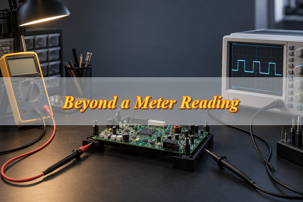
For example, a multimeter may show the expected DC supply voltage even when the circuit experiences brief voltage dips during switching or sudden load changes.
Ordinary voltage measurements cannot fully reveal:
- Voltage transients: Brief spikes or drops that occur too quickly for the display to capture.
- Switching waveforms: Signal shape, timing, and switching behavior.
- Power-supply ripple: Voltage variations that may not appear in a standard DC reading.
- Digital communication: Signal timing, transmitted data, and protocol errors.
An oscilloscope is more suitable for observing voltage changes over time. Some advanced multimeters offer recording or peak-capture functions, but their capabilities vary.
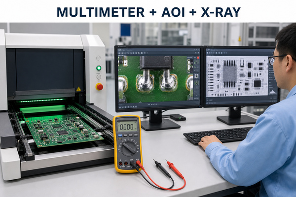
For PCBA projects, voltage checks can verify specified electrical values, while functional testing may be needed to confirm that the assembled board performs its intended operations.
Voltmeter vs Multimeter: Which Should You Choose?
Choose according to whether you need dedicated voltage monitoring, portable measurements, or several testing functions.
| Measurement Task | Recommended Instrument | Reason |
|---|---|---|
| Continuous voltage display | Panel voltmeter | Fixed installation and continuous indication |
| Battery or power-supply checks | Either instrument | Both can measure voltage |
| Multiple PCB test points | Handheld multimeter | Convenient for moving between points |
| Voltage, resistance, and continuity | Multimeter | Combines several measurement functions |
| Extended voltage recording | Suitable logging instrument | Supports measurements over time |
For general electronics and PCB testing, a digital multimeter is usually more practical because it handles several measurement tasks with one instrument.
A panel voltmeter is a better fit when equipment needs a permanently visible voltage reading. For occasional voltage-only checks, either instrument can work if its specifications meet the measurement requirements.
Which Specifications Should You Check Before Buying?
Check the specifications that affect the measurements and environment you actually expect to use.
- Voltage range and AC/DC support: Confirm that the instrument covers the expected voltage and measurement type.
- Accuracy and resolution: Compare the stated measurement uncertainty with the tolerance you need to verify.
- Input impedance: Higher input impedance generally reduces circuit loading, particularly when measuring high-impedance PCB signals.
- AC measurement capability: Check frequency response and whether True RMS measurement is needed for nonsinusoidal AC signals.
- Electrical protection: Verify input ratings, overload protection, appropriate CAT ratings, and test-lead specifications.
- Power and installation: For panel voltmeters, check supply requirements, electrical isolation, mounting dimensions, and operating conditions.
A meter suitable for a low-voltage PCB test point may not be appropriate for building electrical circuits. The voltage range alone does not establish electrical safety.
Use the manufacturer’s datasheet and operating instructions to confirm that the instrument is suitable for your application.
FAQs About Voltmeter vs Multimeter
Q1: Does a digital panel voltmeter need a separate power supply?
A1: Not always. Some models draw power from the voltage they measure, while others require separate power connections. Check the wiring diagram and minimum operating voltage.
Q2: Why does a digital multimeter show a negative voltage?
A2: The red probe is at a lower potential than the black probe. This can happen when the probes are reversed or when measuring a negative voltage rail.
Q3: What does autoranging mean on a multimeter?
A3: Autoranging automatically selects a suitable measurement range. It reduces manual adjustments when checking voltages of different magnitudes.
Q4: How often should a digital multimeter be calibrated?
A4: Follow the manufacturer’s recommendations and your measurement requirements. Instruments used for quality inspections may require scheduled calibration and traceable records.
Q5: Why does a multimeter display OL?
A5: OL commonly indicates an out-of-range measurement or an open circuit, depending on the selected function. Check the instrument’s manual to interpret the reading correctly.
Q6: Why does a multimeter show voltage when its probes are disconnected?
A6: A high-impedance meter may pick up electrical interference at its open inputs. Floating conductors can also produce phantom voltage readings through capacitive coupling. Such readings should never be used alone to establish that a circuit is safe.
Q7: Can a multimeter measure millivolts?
A7: Yes. Many digital multimeters support millivolt measurements. Check the mV range, resolution, and accuracy when measuring small PCB signals.
Q8: Why does a multimeter show fluctuating voltage readings?
A8: Possible causes include unstable supply voltage, electrical noise, poor probe contact, or changing circuit conditions. Fast fluctuations may require an oscilloscope for further investigation.
Q9: What does a low-battery symbol mean on a multimeter?
A9: The instrument’s battery needs replacement or recharging. Low battery voltage may affect instrument operation or measurement reliability.
Q10: Can a multimeter measure voltage through insulated wires?
A10: Standard multimeter probes require suitable electrical contact. Some instruments have non-contact AC voltage detection, but that feature does not provide the same measurement as direct probe contact.
Conclusion
The choice in voltmeter vs multimeter comes down to how you measure voltage. A dedicated voltmeter is useful for continuous voltage indication, while a multimeter is more practical when you need several electrical measurements or move between PCB test points. Compare the specifications of individual instruments before choosing.
EBest Circuit provides PCB manufacturing, PCBA assembly, and testing based on agreed project requirements. For projects involving specified voltage checks or functional testing, send your Gerber files, BOM, assembly drawings, quantities, and testing requirements to sales@bestpcbs.com for a quotation.