





PCB Board Testing Checklist
To test a PCB board, start with visual inspection, then check continuity, resistance, shorts, power rails, component orientation, signal behavior and functional output. A good PCB test process does not rely on one tool only. It combines simple inspection, multimeter checks, controlled power-up, and fixture or system-level testing when the board is part of a product.
This guide explains how to test a PCB board before repair, assembly validation or production release. It is written for engineers, buyers and quality teams who need a practical checklist without turning the article into a lab manual.
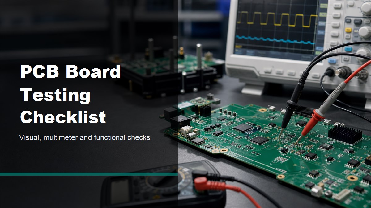
What Should You Check First on a PCB Board?
First, check the board visually before applying power. Many PCB failures can be found before using a meter, especially solder bridges, burned areas, cracked components, lifted pads, reversed parts and contamination.
Look at the PCB under bright light or a microscope if the board has fine-pitch ICs, small passives, BGA packages or dense routing. For a new board, compare the actual assembly against the BOM, silkscreen and assembly drawing. For a failed board, look for local heat damage, darkened solder mask, bulged capacitors, broken connectors and corrosion around exposed copper.
Do not power a board that already shows a visible short, carbonized area, reversed electrolytic capacitor or damaged regulator. Those faults can turn a small repair into a larger failure.
Basic PCB Board Testing Flow
A reliable test flow moves from low-risk checks to powered tests. This reduces the chance of damaging the board while still finding open circuits, shorts and functional defects.
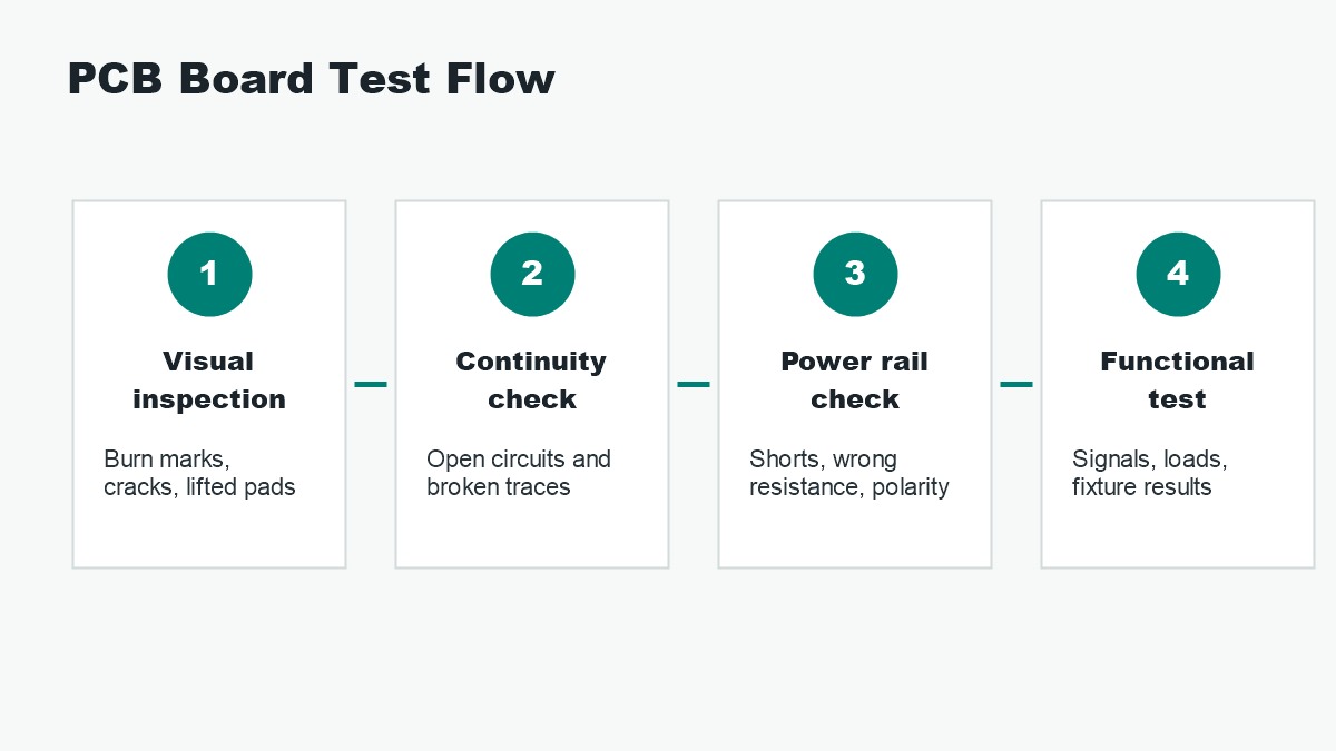
| Test stage | Main purpose | Typical tool | Common finding |
| Visual inspection | Find obvious assembly and damage problems | Light, microscope, inspection camera | Solder bridge, cracked part, corrosion, lifted pad |
| Continuity test | Confirm a path is connected | Digital multimeter | Broken trace, open via, bad connector pin |
| Resistance or short check | Find abnormal low resistance before power-up | Digital multimeter | Shorted rail, wrong component, solder bridge |
| Power rail check | Confirm supply voltage and current behavior | Bench supply, multimeter, oscilloscope | Low rail voltage, overcurrent, unstable regulator |
| Functional test | Verify the board works in its intended circuit | Fixture, firmware, load, system test | Signal error, communication fault, intermittent failure |
How to Test a PCB Board with a Multimeter
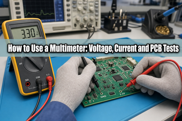
A multimeter is useful for continuity, resistance, diode checks and basic voltage checks. It is not enough for every fault, but it is usually the first practical tool for board-level troubleshooting.
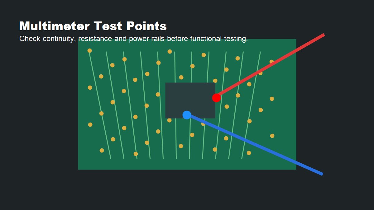
With power off, use continuity mode to check suspected traces, connectors, fuses, switches and test points. Use resistance mode to compare power rails against ground. A very low resistance reading on a rail may indicate a short, but the normal value depends on the circuit, connected ICs and onboard capacitors.
With power on, use DC voltage mode to check input voltage, regulator outputs, reference rails and connector pins. Always place the black probe on a known ground point and keep the red probe steady to avoid slipping across adjacent pins.
How to Check for Shorts Before Powering the PCB
Before applying power, check the main power inputs and low-voltage rails for abnormal shorts to ground. This is one of the safest ways to prevent damage during first power-up.
Measure resistance from each rail to ground and compare it with the expected circuit behavior. A microcontroller core rail, high-current processor rail or LED driver output may naturally show low resistance, so do not assume every low value is a fault. The better method is to compare with a known-good board, schematic expectation or design engineer feedback.
If a rail reads nearly zero ohms, inspect nearby capacitors, IC pins, solder joints, vias and connectors. For repair work, current-limited power injection and thermal observation can help locate the hot component, but this should be done carefully to avoid damaging the PCB.
How to Test PCB Continuity and Broken Traces
Continuity testing confirms whether two points are electrically connected. It is useful for checking traces, vias, connectors, fuses, jumpers and repair wires.
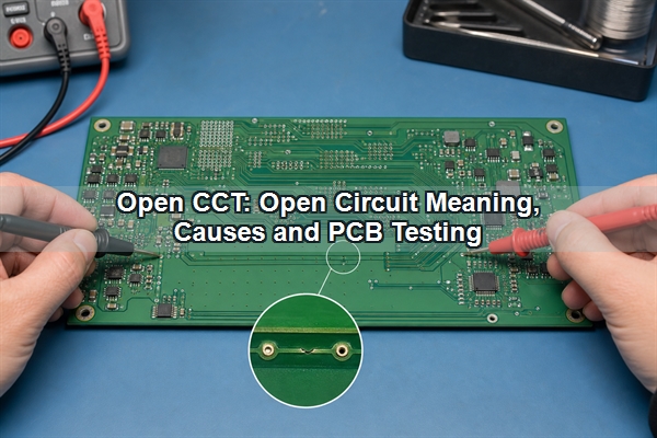
Place one probe at the starting point and the other at the expected connected point. A beep or low resistance usually means the connection exists. No beep can indicate a broken trace, damaged via, cold solder joint, cracked connector pin or wrong test point.
For dense boards, do not drag probes across fine-pitch pins. Use sharp probe tips, stable magnification and the schematic or netlist when available. On multilayer boards, a broken internal trace is harder to confirm without design files, X-ray inspection or specialist failure analysis.
How to Test Components on a PCB Board
Some components can be checked in circuit, but many readings are affected by parallel paths. Treat in-circuit component testing as a screening step, not always a final diagnosis.
Resistors can often be measured if the surrounding circuit does not create a lower parallel path. Diodes and LEDs can be checked with diode mode, but driver ICs and protection circuits may affect the reading. Capacitors may show charging behavior on a resistance range, but accurate capacitance or ESR testing usually needs a suitable meter and sometimes removal from the circuit.
ICs are harder to test directly with a multimeter. For IC-related faults, check supply pins, reset pins, clock behavior, enable pins, communication lines and output signals. An oscilloscope or logic analyzer is usually needed when the failure is dynamic.
Power-Up Testing: What to Watch
Power-up testing should use controlled voltage and current limits whenever possible. A bench power supply with current limiting can prevent a short from destroying traces, regulators or ICs.
Start with the correct input voltage and a conservative current limit. Watch current draw, smell, heat, LED behavior and voltage stability. If the current immediately hits the limit, disconnect power and return to short-circuit checks. If the current looks normal, verify each regulated rail and then check the board under its expected load.
For production boards, a test fixture is better than manual probing. A fixture can contact defined test pads, reduce operator error and record pass/fail results more consistently.
Functional Testing for PCB Boards
Functional testing checks whether the PCB performs its intended job, not only whether traces and voltages exist. This is the step that connects electrical checks with real product behavior.
Typical functional tests include firmware loading, communication checks, sensor input response, relay output, LED output, motor drive, RF response, display behavior or load testing. The correct test depends on the product. A power supply PCB needs load and ripple checks; a control board needs input-output logic checks; a communication board needs interface and signal checks.
For PCB assembly production, functional testing should be documented with fixtures, test limits, firmware version, sample records and failure codes. Without records, repeated failures become harder to trace back to design, assembly or component problems.
Common PCB Board Faults Found During Testing
PCB testing often finds a small set of recurring problems. Knowing these failure patterns helps engineers choose the right next test instead of guessing.
| Fault | Possible cause | Useful check |
| No power output | Input fault, fuse, regulator failure, reversed polarity | Input voltage, fuse continuity, regulator pins |
| Board draws too much current | Shorted capacitor, solder bridge, damaged IC | Rail-to-ground resistance, current-limited power-up |
| Intermittent operation | Cracked solder joint, connector issue, thermal stress | Magnified inspection, gentle flex test, thermal observation |
| Communication failure | Wrong pull-up, bad clock, solder fault, firmware issue | Voltage levels, oscilloscope, logic analyzer |
| One component overheats | Short, wrong part, overload, incorrect orientation | Orientation check, current check, schematic review |
PCB Testing Checklist Before Production
For production or supplier acceptance, PCB board testing should be repeatable. A clear checklist helps avoid depending on one engineer’s memory.
- Confirm PCB revision, BOM revision and assembly drawing match the order.
- Inspect solder joints, polarity marks, connector orientation and visible damage.
- Check main input rail resistance before power-up.
- Check continuity for critical nets, connectors, fuses and test pads.
- Power the board with current limiting during first validation.
- Measure all required voltage rails under normal load.
- Verify clocks, reset lines, enable signals and communication interfaces when relevant.
- Run firmware, fixture or product-level functional tests.
- Record failure symptoms, measured values and repair actions.
- Feed repeated failures back into DFM, DFT, assembly and supplier review.
When Do You Need Professional PCB Testing?
Professional testing is useful when manual checks cannot explain the failure, when the board is high value, or when the issue may affect production quality.
Manual multimeter checks are enough for many simple continuity and power faults. But dense multilayer PCBs, BGA assemblies, impedance-sensitive boards, high-current boards and intermittent failures often need AOI, X-ray, ICT, flying probe testing, boundary scan, functional fixtures or failure analysis support.
If the same defect appears across many boards, do not treat it as a one-off repair issue. It may come from stencil design, reflow profile, component substitution, layout weakness, fixture error, contamination or handling damage.
FAQ
How do you test a PCB board quickly?
Start with visual inspection, then use a multimeter to check shorts, continuity and main power rails. If the board passes those checks, power it with current limiting and run the intended functional test.
Can you test a PCB board with only a multimeter?
You can find many basic faults with a multimeter, including open traces, shorts, wrong resistance and missing DC voltages. Dynamic signal, firmware, timing and communication problems usually need an oscilloscope, logic analyzer or functional test fixture.
What multimeter mode is used for PCB testing?
Use continuity mode for connected paths, resistance mode for rail-to-ground checks, diode mode for diode junctions and DC voltage mode for powered rail checks. Choose the mode based on the fault you are trying to confirm.
How do you know if a PCB is bad?
A PCB may be bad if it has visible damage, abnormal rail resistance, missing voltage, excessive current draw, failed continuity, overheating parts or failed functional output. One symptom is rarely enough; confirm with a structured test sequence.
Should you power a PCB before checking for shorts?
No. Check critical power rails for shorts before applying power, especially on repaired boards, new prototypes and boards with visible solder issues. This reduces the risk of burning traces or damaging ICs.
What is the difference between PCB inspection and PCB testing?
Inspection looks for visible defects such as solder bridges, cracks and wrong orientation. Testing measures electrical behavior, continuity, voltage, current and function. A reliable quality process usually needs both.
Can a PCB pass visual inspection but still fail testing?
Yes. A board can look clean but still have hidden open vias, wrong component values, internal layer problems, firmware issues or signal faults. Visual inspection is only the first layer of quality control.
What tools are commonly used to test PCB boards?
Common tools include a microscope, digital multimeter, bench power supply, oscilloscope, logic analyzer, test fixture, AOI system, flying probe tester, ICT fixture and functional test station.
Final Thoughts
Testing a PCB board is safest when the process moves from visual checks to unpowered electrical checks, then controlled power-up and finally functional verification. This order helps catch obvious faults early while protecting the board from avoidable damage.
If you need PCB fabrication, PCB assembly, prototype validation or production support, BestPCBs can help review manufacturing requirements, testing needs and assembly risk before your board moves into mass production. Contact the engineering team at sales@bestpcbs.com for technical support and a quote.
You may also like


Tags: functional test, multimeter testing, PCB inspection, PCB testing