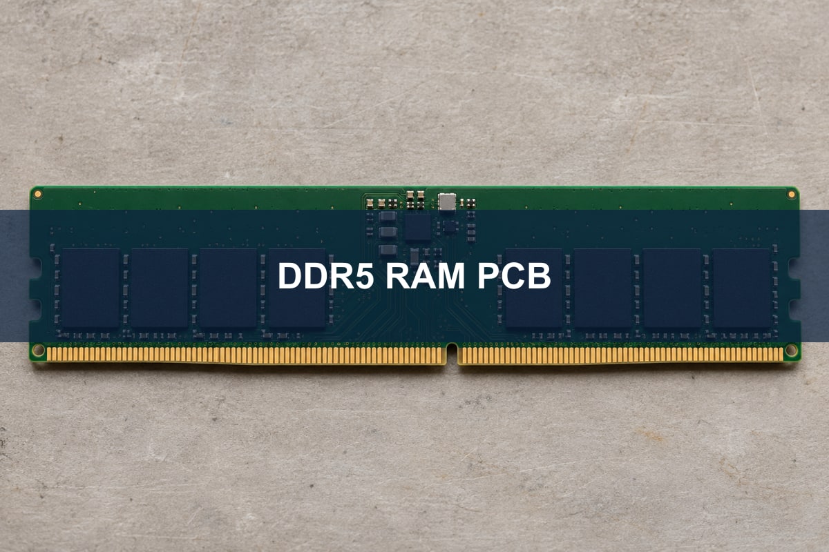
A DDR5 RAM PCB is the circuit board inside a DDR5 memory module. It connects the edge contacts to the DRAM devices, distributes power and carries management signals. The motherboard is a separate PCB: it connects the processor to the memory socket. Both boards affect whether the memory channel works, but their layout rules are not interchangeable.
Imagine a workstation prototype that passes with one module in each memory channel. The next build adds a second module to each channel. Before blaming the new modules for a training failure, check whether the processor, board design and firmware support that population at the intended rate. A DIMM that works by itself does not prove that the fully populated channel has enough margin.
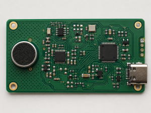
Illustrative rendering. The edge contacts are the boundary between the memory module and motherboard.
What is on a DDR5 RAM PCB board?
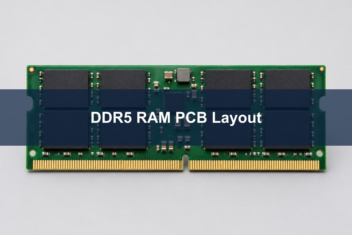
A typical client DDR5 DIMM carries DRAM packages, a power management integrated circuit (PMIC) and a serial presence detect (SPD) hub. The DRAM stores data. The PMIC regulates power locally, and the SPD hub provides configuration information that the platform can use during initialization. Additional devices depend on the module family; do not assume that an unbuffered, registered or clocked DIMM has the same circuit.
A standard non-ECC client DDR5 DIMM divides its data interface into two independent 32-bit subchannels. That split is inside the module interface; it does not mean that plugging in one DIMM populates two motherboard memory channels. When reviewing a diagram, identify whether “channel” refers to the processor’s memory interface or a subchannel within the DIMM before counting sockets or drawing routes.
How to read a DDR5 DIMM pinout
Start with the drawing for the exact module and socket. First verify the contact orientation and mechanical key, then group the contacts by function. Data signals are commonly called DQ; DQS strobes accompany groups of data signals. Clock and command/address signals have separate timing relationships. Power, ground and management contacts must be checked against their own requirements.
On the schematic, verify the connector symbol against the mating drawing, including front and back contact numbering. Next, trace each data group and its strobe back to the controller. A bus that looks connected can still fail if a net swap crosses a group that the controller does not allow. Resolve that discrepancy before using layout tuning to compensate.
DDR5 vs DDR4: What changes on the board?
DDR5 is not a drop-in replacement for DDR4. A desktop module may look similar, but the key position, pin assignment, power design and signaling differ. Compare matching classes of modules rather than treating all DIMMs and SO-DIMMs as interchangeable.
Decision point
DDR4 client DIMM
DDR5 client DIMM
Data interface, non-ECC example
One 64-bit data channel per module
Two independent 32-bit subchannels per module
Nominal DRAM operating supply
1.2 V
1.1 V; this is not the socket input voltage
Module power architecture
Regulation generally on the host board
Local PMIC on the module
Mechanical and electrical fit
Use a compatible DDR4 socket and platform
Use a compatible DDR5 socket and platform
The practical implication for a redesign is that an old connector footprint, rail plan or set of routing constraints cannot be reused as-is. Start with the controller’s DDR5 documentation and the exact module specification, then review the two together.
Inputs for DDR5 RAM PCB design
Freeze the controller, module family, supported slot populations and target data rate before setting routing rules. For example, at a hypothetical design target of 5,600 MT/s, one data unit interval is approximately 179 ps. That number describes the transfer period, not how much skew a route may consume. Get the actual limits from the controller guide for the supported topology.
Parameter to release
Where to check it
What to record
Rate and population
Controller guide and platform support matrix
MT/s, module family, ranks and supported sockets per channel
Impedance and spacing
Controller routing table and approved PCB stackup
Single-ended or differential target in Ω, tolerance, layer and reference
Timing and skew
Signal-group constraints and package delay data
Limit in ps, allowed swaps and included path segments
Power and sideband
Module specification and schematic
Input rails, power sequence and management connectivity
Compare values from documents only when they describe the same controller, module and segment. The published Altera tables, for example, distinguish signals and routing segments for one DIMM per channel. They illustrate how to read a constraint table, not what values to copy into an unrelated design.
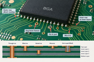
Illustrative rendering. Use the exact module documentation, not component appearance, to identify pin functions and rails.
What to check in a DDR5 RAM PCB layout
Check timing against the electrical path, not just the length displayed in the layout editor. Package routing contributes delay, and traces on different layers may propagate at different speeds. Length matching by itself can therefore hide a timing error. Use the controller’s grouping and delay conventions for DQ, DQS, clock and command/address nets.
Open the approved stackup, the CAD timing report and the controller constraint table together. Verify the signal and reference layers, finished dielectric height and any package delay applied to each group. If the group passes in physical length but fails in time, check the layer assignments and package assumptions before adding more tuning. Also inspect the return path at plane transitions; a continuous-looking trace can cross an opening in its reference.
DDR5 routing topology: Follow the signal groups
Different signal groups can follow different paths. A command/address route feeding several devices can have an ordered chain, while a data group and its strobe need to be checked against the devices and connections they actually serve. Do not apply a fly-by rule to every net or use module-side routing guidance for the host escape.
Draw the processor, socket or soldered DRAM and each branch for the group in question. Mark package, PCB and connector segments separately. If the board uses memory down rather than a socketed module, remove the connector assumption and use the controller’s memory-down rules. If a second socket introduces a branch or a different load, use the model for that population rather than stretching the single-socket routing rules.
DDR5 1DPC vs 2DPC: When the design check changes
One DIMM per channel (1DPC) and two DIMMs per channel (2DPC) are different configurations. Check both how many sockets the board routes and how many modules are fitted. A two-socket channel with one socket empty is not necessarily electrically identical to a design with only one socket; unused routing can remain part of the channel.
In the workstation example, keep the board, firmware and module family fixed. First test the supported single-module population using the specified socket. Then add the second qualified module and verify the supported speed and rank combination for the new population. If the original target is no longer supported, qualify the supported lower rate or revisit the topology. Do not treat an unsupported high-speed boot as proof of usable margin.
Illustrative rendering, not a slot-order recommendation. Use the platform’s population table for the correct sockets.
What DDR5 memory training can tell you
Memory training is part of initialization: the controller and firmware calibrate settings for the installed channel. A training failure is a symptom, not a diagnosis. First compare the actual population, firmware version, default data rate and reported failure stage against a known-good configuration.
For a board bring-up, change one variable at a time and record the trained rate, detected capacity and repeated cold-start results. If only the fully populated case fails, review topology, supported speed, power and routing evidence before assuming a bad DIMM. If it trains successfully, still run the agreed memory stress tests under relevant operating conditions. A passing bare-board impedance result supports the represented trace construction, not assembled channel timing. See the high-speed interconnect validation guide for the distinction between physical connectivity and demonstrated link performance.
FAQ
Does DDR5-5600 mean a 5,600 MHz clock?
No. The designation refers to 5,600 million transfers per second per data pin. Do not use that transfer rate as the clock frequency or as a complete timing budget.
Is one DDR5 DIMM the same as dual-channel motherboard memory?
No. The two subchannels within a DIMM and the processor’s motherboard channel population are different levels. Follow the platform slot map.
Does on-die ECC make a standard DIMM a system ECC module?
No. On-die ECC operates inside the DRAM device. End-to-end memory error protection also depends on the module and controller interface and platform support.
Can UDIMM and RDIMM be mixed?
Do not assume compatibility. The registered module has a different command/address architecture. Use the platform’s supported module classes and population rules.
Is there a universal DDR5 PCB layer count?
No. Routing density, escape geometry, reference planes, power delivery and the manufacturing process determine the stackup. A layer count alone does not establish signal integrity.
Should I always use the second socket first?
No. Slot names and recommended population order are board-specific. Use the motherboard or platform manual, not the physical position alone.
What should I record when a memory test passes?
Record the actual rate, firmware, slot population, module part numbers, test duration and relevant operating conditions. The result only supports the configuration that was tested.
What should I send for a PCB fabrication review?
Send the approved stackup, routed signal groups, impedance targets and tolerances, fabrication files and coupon requirements. Separate any request for assembly or system-level validation from the bare-board requirements.
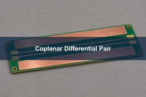
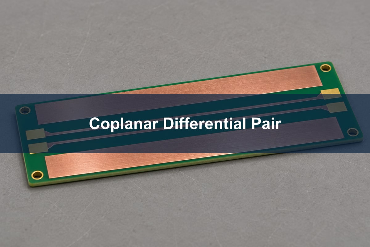
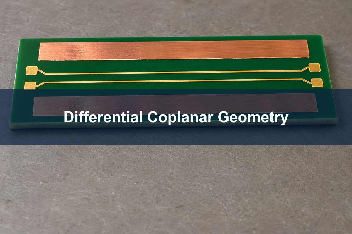
A coplanar differential pair has two signal traces and nearby reference copper on the same PCB layer. If you move that copper close to an existing pair, do not reuse the old impedance result. The gap to ground becomes part of the cross-section, along with the gap between traces and the distance to any reference plane underneath.
Suppose an engineer has sized a surface differential pair above a continuous plane, then adds ground copper beside it to fit a connector escape. The decision is not simply whether ground copper is good or bad. It is whether the final layout still matches the model used to set the trace width and gaps. Here is how to check that from the stackup through the test report.
Illustrative rendering. The two signal traces and the copper beside them are separate parts of the cross-section.
Coplanar differential pair meaning: Which copper counts?
“Differential” describes how the two signals work together; “coplanar” describes where the reference copper is placed. In differential operation the two conductors carry opposite signals. A nearby conductor still affects the electric field, even though the two signal traces are coupled to each other. Two traces on the same layer are not, by themselves, what a PCB calculator means by a coplanar pair.
Open the final copper view and look across a straight section of the pair, not just at its net names. Identify the gap between the signals and the gap from each signal to its outside ground copper. Then open the stackup and identify any reference plane above or below. These are separate inputs. A calculator icon is useful only if it shows the same arrangement.
Coplanar differential pair vs non coplanar: Which model fits?
Choose the model that matches the board. A conventional surface pair over a plane can be modeled as edge-coupled microstrip when nearby side copper is absent or shown to have negligible effect. A grounded coplanar pair has both adjacent ground and a reference plane. It gives the designer another geometry variable, but that variable also has to be controlled in fabrication.
Cross-section
Reference geometry
When to use the model
Edge-coupled microstrip
Plane below; no significant side copper
The approved layout keeps neighboring copper far enough away for the modeled tolerance
Grounded coplanar pair
Side grounds and a plane below
Both sets of references are present in the routed cross-section
Coplanar pair without backing plane
Side grounds; no continuous lower plane in the modeled region
The stackup really lacks that plane and the tool supports this structure
In the example, keep width, pair spacing, material and bottom plane unchanged. In version A, side copper is pulled back and a sensitivity check shows its effect is immaterial: retain the microstrip model. In version B, move only the side copper inward: rerun the model with both side grounds present. If the result leaves the project’s impedance window, change the geometry or restore the keepout. Do not adopt a universal clearance multiple in place of that check.
Key dimensions of a differential coplanar waveguide with ground
The parameter that is easiest to miss is the side-ground clearance. Measure it from the outside edge of each signal trace to the adjacent copper edge, separately from the edge-to-edge spacing inside the pair. The table gives the inputs to collect before asking a solver for an answer; it deliberately does not prescribe a universal width or gap.
Input
Where to obtain it
Why it changes the answer
Finished trace width and copper thickness, mm
Fabricator’s impedance proposal or approved stackup
Finished geometry differs from a nominal copper weight or artwork width
Pair spacing and both side-ground clearances, mm
Final copper or fabrication artwork; confirm edge-to-edge convention
Pair coupling and side-ground coupling are separate effects
Dielectric height and Dk
Approved stackup and material model
Use the height to the actual reference and the appropriate dielectric value, not overall board thickness
Solder mask and local geometry
Final mask artwork and solver model
Coating and asymmetric copper can change what the simple cross-section represents
For the same pair, a plane on the next layer is not equivalent to a plane across the entire board thickness. Locate the actual signal and reference layer identifiers on the approved stackup. If the far-side plane is broken at the connector, mark that transition for separate review; a uniform 2D model does not evaluate the break.
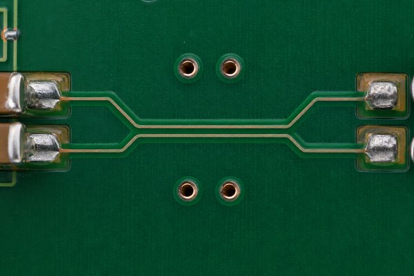
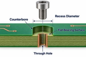
Illustrative rendering. Verify the inner pair gap and the outer ground clearances independently in the final CAD artwork.
What to enter in a coplanar differential pair impedance calculator
Compare two calculators only after making their cross-sections and inputs equivalent. Start with the reference layers, finished dielectric height and copper thickness, then check Dk, mask, trace width, pair gap and outer gap. One tool may include mask or side copper in a way the other does not. Altium’s impedance documentation describes both the coplanar models and input differences that can explain disagreement.
Save an input sheet with units and a cross-section sketch, then change one parameter at a time in the same tool. This is more useful than averaging two outputs. If a calculator assumes symmetry but the real layout has ground much closer on one side, use a model that supports the actual geometry. At pads and layer changes, supplement the cross-section model with a suitable transition analysis or measurement.
Differential pair impedance formula
For a symmetric pair in odd-mode excitation, differential impedance is twice the odd-mode impedance of one line: Zdiff = 2 × Zodd. It is not necessarily twice the impedance of an isolated trace, because the neighboring signal and reference copper affect the fields.
For a teaching example, take a project target of 100 Ω ±10%, not a universal interface requirement. Its acceptance window is 90–110 Ω. If a symmetric model returns 48 Ω odd mode, the calculated differential impedance is 96 Ω. If a second model of the same pair with closer side copper returns 44 Ω odd mode, the result is 88 Ω. Those input values illustrate the decision and are not solver predictions for a specific geometry. The first result is in the window, the second is not; neither replaces a tolerance analysis or measurement.
Differential pair routing guidelines
Keep the final pair and its references consistent with the modeled profile. Repour copper and inspect the finished artwork before release: a ground island, neckdown, asymmetric clearance or plane split can appear after the initial routing check. Length matching does not make those cross-section changes disappear.
For the connector escape in the example, mark where the narrow fanout begins and ends. If the required ground clearance cannot be maintained there, review it as a local transition rather than applying a new trace width to the entire route. Check that adjacent copper is tied to the intended reference and that layer changes have an appropriate return path. Use the microstrip PCB guide for the underlying plane-referenced geometry.
What a PCB impedance test coupon can verify
A coupon is useful only when it represents the structure you intend to accept. For the coplanar route, ask the fabricator to identify the coupon’s stackup revision, signal layer, reference layers, pair spacing and side-ground arrangement. A coupon for ordinary differential microstrip can pass while saying nothing about a nearby-ground variant.
Check the impedance report against the fabrication drawing: match the coupon ID to the layer and geometry, confirm the target and tolerance, and identify the evaluated segment. If the report only shows “100 Ω pass” with no link to the modeled construction, request the coupon mapping and trace before accepting it as evidence for the coplanar pair.
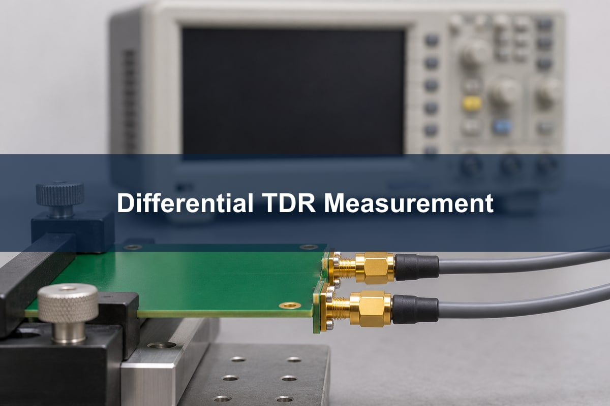
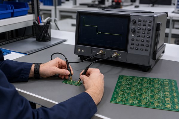
Illustrative rendering. A differential coupon result needs a known connection setup and an identified measurement region.
How to read a differential TDR measurement
A differential time-domain reflectometry (TDR) trace shows impedance changes along a path under differential stimulus. Agree on the fixture or launch reference, the part of the trace to evaluate and the pass window before comparing results. A connector discontinuity near the launch should not be mistaken for the steady region of a uniform coupon.
If the coupon is in range but the assembled link still fails, do not immediately change the straight-line width. Compare the actual launch, return path, layer changes and connector geometry with what the coupon omits. Use an appropriate link-level test for the required signal behavior. A passing coupon supports impedance control of the represented cross-section; it does not certify loss, mode conversion or the performance of the assembled channel.
FAQ
Can I leave a floating copper pour beside the pair?
Do not model a floating island as an ideal grounded reference. Inspect the final copper and its net connections. Remove the island or evaluate the actual structure if it must remain.
Does the quoted side gap include solder mask?
The gap normally refers to the copper geometry, while mask is a separate dielectric input. Confirm the tool’s drawing and the fabricator’s dimensional convention before comparing outputs.
Should I change pair spacing or side clearance first?
Start with the dimension the layout can actually change. Sweep it independently against the same stackup; if the result is too sensitive to production variation, choose a more tolerant geometry instead of optimizing only the nominal result.
Is an equal-length pair always symmetric?
No. Both traces can be the same length while seeing different pad shapes, nearby copper or plane openings. Check the surrounding geometry on both sides where the layout changes.
Can I use the same dimensions on a four-layer redesign?
Not without recalculating. The reference plane may be closer and the dielectric construction may differ even when the board thickness is unchanged. Get the new stackup and recheck the same routing profile.
Can a single-ended TDR reading be doubled to verify the pair?
Not if it is an ordinary single-ended reading rather than an odd-mode measurement. Use a differential setup or an explicitly valid mode conversion method and check how the instrument reports impedance.
Does every copper edge need a via fence?
No universal pitch or requirement applies. First decide whether the side copper is part of the controlled profile, then design its connection to the intended reference for the actual geometry and frequency range.
What files should I send for an impedance review?
Send the layer stackup, signal and reference layers, target with tolerance, relevant copper artwork, and the width and gap conventions. Highlight any local geometry that cannot follow the uniform cross-section.
Differential pair PCB design works when two coupled traces carry opposite-polarity signals through a controlled geometry and an uninterrupted return environment. Good results depend on the complete channel, not on matching two visible trace lengths or copying a width-and-gap rule from another stackup.
Translate the interface requirement into impedance geometry, route the pair without avoidable discontinuities, set a defensible length-matching limit, and release enough data for fabrication and verification. For an early manufacturability check on a real layout, send the stackup, target impedance, Gerber or ODB++ data, and relevant interface requirements to sales@bestpcbs.com for a free DFM review.
What Is a Differential Pair in PCB Design?
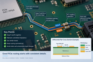
A differential pair is a matched signal path in which the receiver responds mainly to the voltage difference between two conductors. The two traces are usually named positive and negative, but the essential behavior is the equal-and-opposite signal relationship, not the labels. The pair should be treated as one transmission structure from transmitter pins through vias, connectors, and PCB routing to the receiver pins.
In differential pair PCB design, coupling between the two traces can help the receiver reject noise that appears similarly on both conductors. That benefit is conditional. Unequal geometry, different reference-plane exposure, asymmetric vias, stubs, or unequal loading can convert part of the differential energy into common-mode energy. A visually neat pair can therefore perform poorly if its electrical environment is not symmetric.
The controlled properties are the pair’s target differential impedance, trace geometry, reference plane, transition structure, allowed discontinuities, and skew budget. Their limits come from the interface specification and system timing analysis, then become stackup, layout, and fabrication controls.
How Do Differential Pairs Improve Signal Integrity in High-Speed PCBs?
Differential signaling improves noise tolerance when both traces experience closely matched electrical conditions. A receiver subtracts one input from the other, so noise coupled equally into both traces is partly rejected. The opposite currents also produce fields that can partially cancel at a distance, which can reduce radiated coupling compared with a poorly controlled single-ended route.
The benefit is not automatic for a high-speed PCB differential pair. Common-mode rejection deteriorates when one trace crosses a plane split, sees a different via field, passes closer to a noisy aggressor, or accumulates substantially different delay. Mode conversion can then increase emissions, receiver jitter, and eye closure even if continuity and nominal impedance appear acceptable.
Evaluate signal integrity across the full channel because the launch, connector, package, vias, routing, terminations, and receiver all contribute. Apply the same return-path and transmission-line checks described for controlled signal transmission PCB design.
How Is Differential Pair PCB Impedance Calculated from the Stackup?
Differential impedance is calculated from the pair geometry, conductor properties, and surrounding dielectric structure. It is not determined by trace width alone. The calculation must use the actual routing layer and the intended fabricated stackup, including the reference-plane relationship.
The following inputs are the minimum useful basis for a differential pair impedance calculation:
Trace geometry: define finished conductor width, pair spacing, copper thickness, and whether the traces are external microstrip or internal stripline.
Dielectric geometry: define the finished distance from the signal layer to each relevant reference plane, not merely the prepreg or core catalog thickness before processing.
Material model: use a design dielectric constant and loss model appropriate to the laminate, frequency range, and solver method rather than treating one catalog Dk value as universal.
Fabrication effects: account for etching, trapezoidal conductor shape, copper plating where applicable, resin flow, and solder mask on external layers when these effects are material to the target.
Input
Electrical effect
Release or verification action
Trace width
Changes each conductor’s single-ended impedance and its interaction with the partner trace
State whether the value is design width or expected finished width
Pair spacing
Changes mutual coupling and therefore differential impedance
Define edge-to-edge or center-to-center convention explicitly
Plane distance
Changes field concentration and impedance sensitivity
Confirm the finished dielectric thickness with the fabricator
Dielectric properties
Affect impedance, delay, and loss
Identify the approved material family and design-property basis
Copper profile and thickness
Affect effective geometry and conductor loss
Include finished copper requirements and relevant foil constraints
A solver result is therefore conditional on its inputs. If the fabricator adjusts width to meet impedance, the released drawing should make that permission explicit and retain a controlled record of the approved stackup and resulting geometry.
The impedance calculation record should identify the solver assumptions, differential target, and exact stackup revision. This prevents a valid result from being reused after a material or layer-geometry change makes it obsolete.
How Should You Use a PCB Differential Pair Impedance Calculator?
Use a PCB differential pair impedance calculator for early geometry exploration, then confirm the production geometry with the fabricator’s stackup and field-solver method. Different calculators can disagree because they use different closed-form equations, conductor models, dielectric assumptions, and solder-mask treatment.
Lock the interface requirement: obtain the target impedance and any permitted tolerance from the applicable interface specification or system requirement; do not choose a familiar value by habit.
Enter one real stackup: use the intended routing layer, reference planes, finished dielectric distances, copper thickness, design Dk basis, width, and edge-to-edge spacing.
Run sensitivity checks: vary width, spacing, dielectric thickness, and material properties within realistic fabrication ranges to identify which input dominates the result.
Compare methods carefully: if two tools disagree, compare their input definitions and models before averaging their outputs; the disagreement is evidence that the assumptions need review.
Close the fabrication loop: submit the target and preliminary geometry for stackup confirmation, then update the layout and controlled-impedance drawing to match the approved production construction.
An online calculator is most useful as a screening tool. A 2D field solver or fabricator impedance model better represents multilayer geometry and manufacturing effects, but even that result must remain tied to the same material and stackup revision used for production.
How Do You Select Differential Pair Trace Width and Spacing?
Select differential pair trace width and spacing together because both affect impedance, coupling, loss, routing density, and manufacturability. There is no universally correct width-to-gap ratio. A geometry that works on one layer may miss the target after a stackup, copper, or material change.
Width is often constrained by loss, current density, breakout space, and fabrication capability. Differential pair spacing controls mutual coupling but also affects how strongly the pair depends on its partner compared with the reference plane. Very tight spacing can make etch variation more influential and may complicate neck-down areas; wide spacing reduces pair coupling and increases the need for consistent reference-plane behavior.
Start with the stackup: choose the routing layer and reference plane before optimizing width and spacing.
Prioritize the target: solve for the required impedance while preserving manufacturable geometry and acceptable channel loss.
Control transitions: define how far neck-down may extend near pads, vias, or connectors and include those regions in channel review.
Check process sensitivity: select geometry that remains acceptable across realistic finished-width and dielectric-thickness variation.
Treat differential pair spacing as a stackup-specific design result, not a reusable rule of thumb. Record the final geometry by impedance class and layer so that layout, CAM review, and coupon verification refer to the same definition.
How to Route Differential Pair Traces in PCB?
Route the two conductors as one continuous electrical structure with consistent geometry, reference, and transition symmetry. The route should be planned before dense single-ended signals consume the cleanest corridors.
Confirm endpoints and constraints: identify the transmitter and receiver pin assignments, polarity, target impedance, routing layer, allowed via structure, and timing budget from controlled design inputs.
Plan the return environment: choose a path over a continuous reference plane and avoid splits, voids, antipad discontinuities, and reference changes that force return current to detour.
Route the pair together: maintain the approved width and spacing through the main path, keeping the two traces exposed to similar nearby copper, components, and aggressors.
Minimize discontinuities: keep stubs short, limit unnecessary vias, and avoid long neck-down regions; each discontinuity should have a clear routing or breakout reason.
Match transitions: use symmetric via structures and comparable pad, antipad, and escape geometry for both conductors; review connector and package launches as part of the channel.
Correct local skew near its source: add only the delay required by the interface budget and avoid dense serpentine patterns that introduce extra coupling or impedance disturbance.
Verify the finished route: run geometry and connectivity checks, inspect reference continuity and coupling context, and use channel simulation when edge rate, loss, or discontinuity severity makes it necessary.
Accept the route only after checking geometry and reference continuity across the complete channel, including breakout and transition regions where the traces cannot remain perfectly parallel.
Which Differential Pair PCB Layout Guidelines Control Vias and Reference Planes?
The most consequential differential pair PCB layout guidelines keep both conductors symmetric through layer transitions and preserve a short return path between reference planes. A via transition changes capacitance, inductance, coupling, and return-current geometry, so it cannot be treated as a neutral connection.
Use paired transitions: keep signal-via type, barrel length, pad stack, antipad, and stub condition equivalent for the two traces.
Provide return continuity: when the reference changes between planes, place suitable stitching paths nearby according to the reference-net and stackup design.
Control via stubs: evaluate unused barrel length against channel bandwidth; backdrilling or alternative via structures are design choices, not universal requirements.
Avoid plane voids: do not route across splits, cutouts, large antipad fields, or sparse reference copper without analyzing the return-path effect.
Review coupled neighborhoods: maintain adequate separation from unrelated high-speed routes, clocks, switching nodes, and board edges based on coupling analysis rather than one generic spacing multiple.
For a complex differential pair PCB layout, inspect the launch and transition geometry in 3D or with a suitable electromagnetic model when a simple cross-section solver cannot represent the discontinuity. Judge the transition against the channel requirement rather than its apparent symmetry in a 2D screenshot.
How Much Differential Pair Length Matching Is Actually Required?
Differential pair length matching should be based on allowed intra-pair skew, not on a universal length difference. The permitted mismatch depends on the interface, signal edge rate, receiver tolerance, package skew, connector skew, and the propagation delay of the actual stackup.
Intra-pair matching controls the time difference between the positive and negative conductors of one pair. Inter-pair matching controls timing among separate lanes or pairs. These are different constraints and should not share one rule unless the interface specification explicitly makes them identical.
Convert the electrical skew budget into a physical-length budget using the propagation delay for the routed layer, then subtract known package, connector, and breakout contributions. Correct mismatch close to the location that created it. Long, tightly folded meanders can add self-coupling and local impedance disturbance, so a nominally perfect length report does not guarantee a better channel.
The layout release should identify which nets use intra-pair matching, which groups require inter-pair matching, the source of each limit, and whether the CAD tool measures pad-to-pad routing, pin-to-pin delay, or another defined path. This prevents a tolerance from being applied to the wrong electrical quantity.
What Causes Differential Pair Signal Integrity Failures?
Differential pair signal integrity failures usually arise from discontinuity, asymmetry, excessive loss, crosstalk, or an incorrect constraint source. A diagnosis should connect the observed symptom to a physical mechanism and a measurement or simulation that can distinguish it from other causes.
Observed symptom
Likely mechanism
Useful verification
Corrective direction
Reflection or eye closure near a transition
Via, connector, neck-down, or plane discontinuity
TDR localization and channel simulation
Refine the transition geometry and return path
Unexpected emissions or common-mode energy
Pair asymmetry, skew, or unequal reference exposure
Common-mode conversion analysis and near-field probing
Restore symmetry and remove the source of unequal delay
Intermittent margin across builds
Geometry or material sensitivity near the limit
Coupon data, cross-section results, and lot correlation
Adjust nominal geometry or tighten the relevant controlled input
Crosstalk that changes with activity
Insufficient separation or long parallel exposure to aggressors
Victim-aggressor simulation or oscilloscope correlation
Increase isolation, change layer assignment, or shorten exposure
Calculator and production results disagree
Different stackup, Dk, copper, or geometry definitions
Input-by-input model comparison and coupon review
Reconcile the production stackup and finished geometry basis
When reviewing a failing differential pair PCB, begin with the channel map and locate where geometry, reference, or symmetry changes. This narrows the investigation more effectively than changing multiple routing rules at once.
What Should You Include in a Differential Pair PCB Manufacturing Package?
Release a differential pair PCB as a controlled impedance construction with explicit net classes, stackup assumptions, fabrication authority, and verification requirements. Gerber data alone may show the artwork, but it does not reliably communicate the electrical intent or which dimensions the fabricator may tune.
Impedance schedule: list each differential impedance class, target, tolerance source, routing layer, and representative net names.
Stackup definition: identify copper layers, reference planes, finished dielectric thicknesses, approved material family, and the design-property basis used for modeling.
Geometry convention: state finished or design trace width, edge-to-edge spacing, copper thickness, and any permitted fabricator adjustment.
Coupon plan: define whether a representative impedance coupon is required, which structures it covers, and what report or data should be returned.
Verification method: identify the agreed TDR or other measurement approach, reporting format, and project-specific acceptance basis.
Change control: require review when material, stackup, copper, trace geometry, or impedance-adjustment assumptions differ from the approved construction.
Ask for the production stackup and impedance report to be revision-linked to the order. For high-risk channels, cross-section data and representative coupon results can help separate artwork errors from fabrication variation. These records also make later repeat orders and engineering changes easier to compare.
Frequently Asked Questions About Differential Pair PCB Design
Q1: Is differential impedance always twice the single-ended impedance?
A1:No, coupling changes the relationship. When the traces are electromagnetically coupled, the differential impedance depends on both each trace’s impedance and their mutual interaction. The result approaches a simple two-times relationship only under limited weak-coupling conditions. Use the pair geometry and actual stackup in an appropriate calculator or field solver.
Q2: Should a differential pair remain at the same spacing everywhere?
A2:Keep the approved spacing through the main route, but controlled local exceptions may be necessary. Pads, vias, connectors, and breakout regions can force geometry changes. Minimize their length, keep both sides symmetric, and include electrically significant transitions in simulation or review instead of assuming the main-route impedance represents the entire channel.
Q3: Can differential pairs cross a split in the reference plane?
A3:A plane split is normally a return-path discontinuity and should be avoided. Crossing it can enlarge the current loop, increase radiation, and create mode conversion. If a design constraint makes a reference transition unavoidable, engineer a defined return path and validate the transition rather than routing across an uncontrolled void.
Q4: Does polarity swapping fix a routing problem?
A4:Polarity inversion is interface-dependent and does not repair poor channel geometry. Some receivers support polarity reversal, but that feature must be confirmed in the device or interface documentation. Even when allowed, the two traces still require symmetric transitions, continuous references, controlled impedance, and an acceptable skew budget.
Q5: Should differential pair meanders be placed anywhere there is space?
A5:Place only the required correction near the source of mismatch. Dense or long meanders can couple to themselves, disturb impedance, and add more delay than a simple geometric estimate suggests. Keep adequate spacing between adjacent serpentine segments and verify the result against the electrical skew budget.
Q6: Is a 90-ohm or 100-ohm target suitable for every interface?
A6:No, the target must come from the applicable interface specification. Those values are common examples across different interface families, not interchangeable defaults. Confirm the differential target, tolerance, reference test condition, and whether connector or package effects are included before creating the PCB rule.
Q7: Does equal CAD length guarantee equal electrical delay?
A7:Equal reported length does not guarantee equal delay. The traces can experience different dielectric environments, reference discontinuities, vias, connector paths, or local coupling. For demanding channels, evaluate electrical delay and skew across the complete path rather than relying only on a geometric length column.
Q8: When is backdrilling worth considering?
A8:Consider backdrilling when unused via stubs materially reduce channel margin. The decision depends on data rate, edge content, via length, board thickness, connector topology, and the measured or simulated channel response. It is not required for every differential pair and should be specified with achievable stub and registration limits.
Q9: Why can an impedance coupon pass while the product channel still fails?
A9:A coupon represents selected fabrication geometry, not every product discontinuity. It may confirm the line construction while the product still contains problematic launches, vias, plane voids, connectors, or routing asymmetry. Use coupon data to verify fabrication, then diagnose the full product channel separately.
Q10: What files help a fabricator review a controlled differential pair design?
A10:Provide the artwork and the electrical construction requirements together. Useful inputs include Gerber or ODB++, NC drill data, stackup, impedance schedule, net names, width-and-spacing convention, material requirements, coupon request, and any permission to adjust geometry. Add assembly or connector information when it affects the channel review.
Conclusion
A reliable differential pair begins with an interface-derived electrical requirement and ends with a revision-controlled manufacturing record. Calculate impedance from the real stackup, route both conductors through the same electrical environment, distinguish intra-pair from inter-pair matching, and verify production with the evidence appropriate to the channel risk.
If your design is approaching layout release, send the Gerber or ODB++, stackup, impedance schedule, target interfaces, quantities, and requested verification records to sales@bestpcbs.com. EBest Circuit can review the controlled-impedance fabrication inputs and return project-specific DFM questions and quotation requirements without replacing the interface owner’s final electrical validation.
This website uses cookies to enhance your experience, remember your preferences, and help us understand how visitors use our site. You can accept all cookies, reject non-essential cookies, or manage your settings.
This website uses cookies to improve your experience while you navigate through the website. Out of these cookies, the cookies that are categorized as necessary are stored on your browser as they are essential for the working of basic functionalities of the website. We also use third-party cookies that help us analyze and understand how you use this website. These cookies will be stored in your browser only with your consent. You also have the option to opt-out of these cookies. But opting out of some of these cookies may have an effect on your browsing experience.
Necessary cookies are absolutely essential for the website to function properly. These cookies ensure basic functionalities and security features of the website, anonymously.
Cookie
Duration
Description
cookielawinfo-checkbox-analytics
11 months
This cookie is set by GDPR Cookie Consent plugin. The cookie is used to store the user consent for the cookies in the category "Analytics".
cookielawinfo-checkbox-functional
11 months
The cookie is set by GDPR cookie consent to record the user consent for the cookies in the category "Functional".
cookielawinfo-checkbox-necessary
11 months
This cookie is set by GDPR Cookie Consent plugin. The cookies is used to store the user consent for the cookies in the category "Necessary".
cookielawinfo-checkbox-others
11 months
This cookie is set by GDPR Cookie Consent plugin. The cookie is used to store the user consent for the cookies in the category "Other.
cookielawinfo-checkbox-performance
11 months
This cookie is set by GDPR Cookie Consent plugin. The cookie is used to store the user consent for the cookies in the category "Performance".
viewed_cookie_policy
11 months
The cookie is set by the GDPR Cookie Consent plugin and is used to store whether or not user has consented to the use of cookies. It does not store any personal data.
Functional cookies help to perform certain functionalities like sharing the content of the website on social media platforms, collect feedbacks, and other third-party features.
Performance cookies are used to understand and analyze the key performance indexes of the website which helps in delivering a better user experience for the visitors.
Analytical cookies are used to understand how visitors interact with the website. These cookies help provide information on metrics the number of visitors, bounce rate, traffic source, etc.
Advertisement cookies are used to provide visitors with relevant ads and marketing campaigns. These cookies track visitors across websites and collect information to provide customized ads.