PCB manufacturing PCB manufacturing
Home > Blog

counterbore hole

Counterbore: Symbols, Hole Dimensions and PCB Design
Saturday, October 3rd, 2026

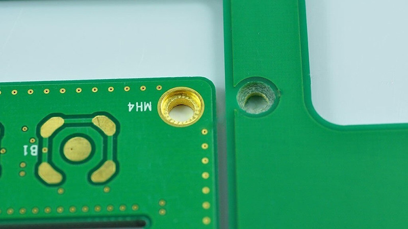
A counterbore is a cylindrical, flat-bottomed recess around a smaller hole. It provides space for a screw head, washer or other hardware to sit below the surrounding surface. A drawing must define the smaller hole diameter, recess diameter and recess depth; the screw thread size alone is not enough.

On a PCB, the recess also removes insulating material and may approach internal copper. The design therefore needs a remaining-thickness calculation as well as a fastener-fit check. A counterbore that fits a metal bracket can be too deep for the circuit board mounted beside it.
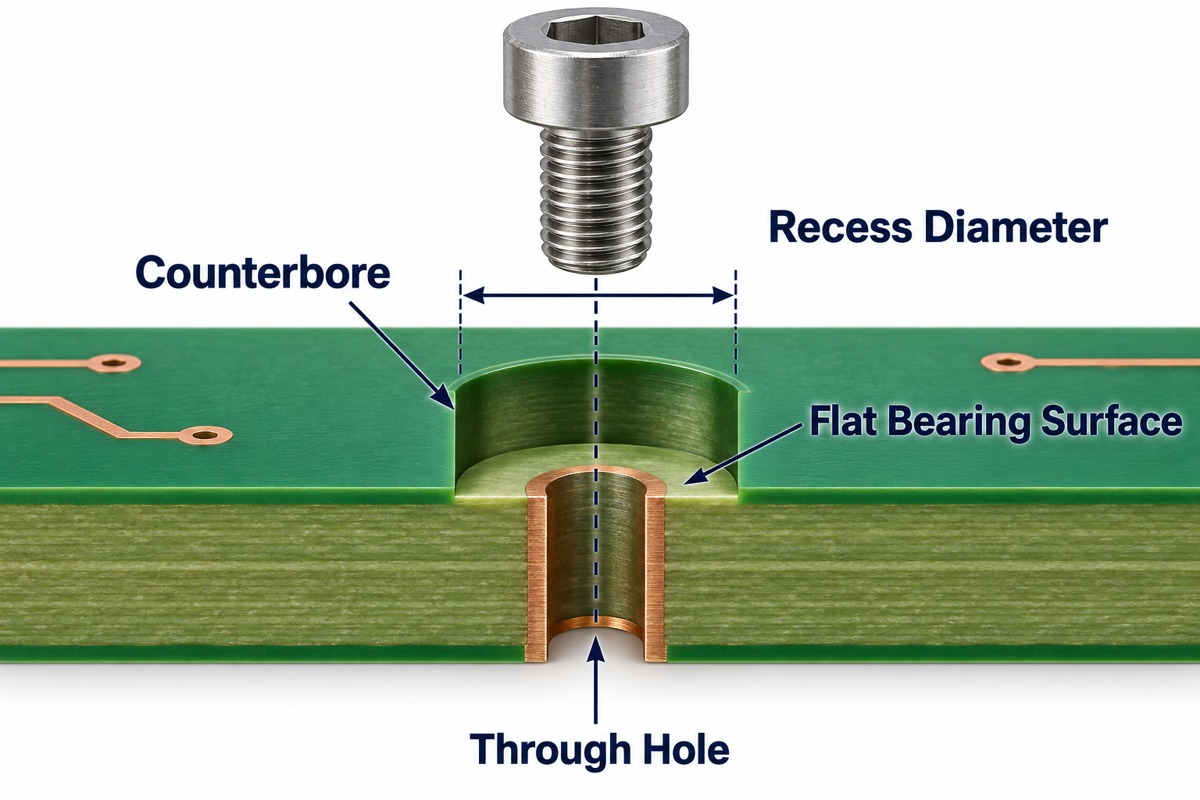
Cutaway showing a counterbore recess, flat bearing floor, through hole and socket-head screw

Key Takeaways

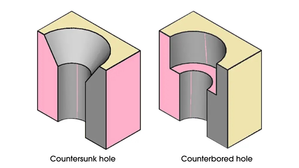
  • A counterbore has straight walls and a flat bearing floor; a countersink has a conical seat.
  • The ⌴ symbol identifies a counterbore. Diameter, depth, machining side and tolerances make the feature manufacturable.
  • Choose recess dimensions from the actual screw head and washer, not just the nominal thread size.
  • An ordinary M3 socket-head cap screw can have a 3 mm head height, so it cannot be fully recessed into a 1.6 mm PCB.
  • Check minimum board thickness minus maximum recess depth, then review the remaining structure and internal copper.
  • Copper clearance follows the full recess boundary, not only the smaller through hole.
  • Inspection should check diameter, depth, location, floor condition and hardware fit.

What Is a Counterbore Hole?

A counterbore hole is a stepped hole with a larger cylindrical opening above a smaller bore. The annular floor supports the underside of the fastener head or washer, while the smaller bore provides a path for the screw shank.

Feature Geometry Primary purpose
Counterbore Cylindrical recess with a flat floor Accommodate a cylindrical head or washer
Countersink Conical recess Seat a matching flat-head screw
Spotface Shallow machined flat seat Create a suitable bearing surface
Clearance hole Single-diameter bore Allow the screw shank to pass without thread engagement

The word also names the cutting tool used to make this recess. A request for a “counterbore” should therefore distinguish the finished feature from the tool. The smaller hole can be through or blind, although PCB mounting designs commonly use a through hole.

When Does a PCB Need a Counterbore?

A PCB needs a counterbore when hardware must sit below its surface and the board has enough material to retain a sound bearing floor. Examples include a recessed mounting screw near an enclosure wall or hardware that would otherwise interfere with a cover.

At EBest Circuit, we support counterbore-hole designs within our FR4 PCB fabrication services. Send the screw drawing and board stackup with the mechanical detail so we can review the machining side, remaining material and copper clearances before production.

Recessing a screw does not automatically make its joint stronger. Where the board is too thin, move the recess into the enclosure or mounting bracket, or use a suitable standoff. Our earlier article on counterbores in PCB design and manufacturing introduces related mounting applications.

Counterbore Symbol and Drawing Callout

The counterbore symbol is ⌴, placed before the recess diameter. A complete counterbore callout also identifies depth and the smaller hole, with units and tolerances supplied by the detail or drawing notes.

For example, an illustrative drawing could specify 4X Ø3.4 THRU; ⌴ Ø6.5, DEPTH 3.2; TOP SIDE; ALL DIMENSIONS IN mm. This describes four through holes, each with a larger top-side recess. It is a reading example, not an approved PCB design or a universal M3 standard.

  • 4X: four identical features.
  • Ø3.4 THRU: the smaller bore passes through the part.
  • ⌴ Ø6.5: the cylindrical recess is 6.5 mm in diameter.
  • DEPTH 3.2: the recess floor lies 3.2 mm below the specified top reference surface.
  • TOP SIDE: the feature is machined from the identified face.

Add dimensional tolerances, hole location and the intended plated or non-plated condition before releasing the drawing. A simple “M3 counterbore” note leaves the screw family, washer and recess geometry unresolved. If a font does not display ⌴ clearly, retain the section view and use an explicit COUNTERBORE note.
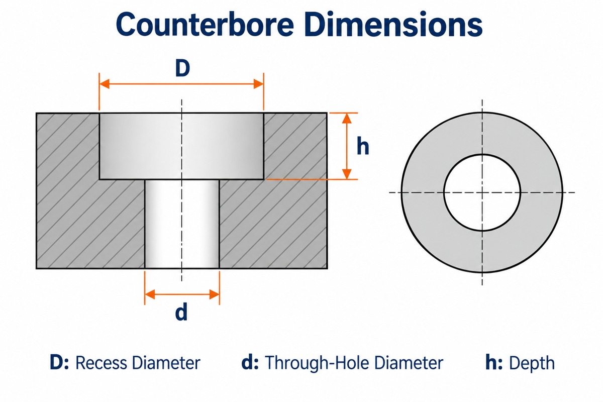
Section and top views identifying counterbore diameter D, through-hole diameter d and depth h

How Do You Choose Counterbore Diameter and Depth?

Choose the diameter to clear the maximum screw-head or washer diameter, and choose the depth to achieve the required installed head position. Check these dimensions against the purchased fastener drawing, including its tolerances.

A standard-height M3 socket-head cap screw commonly has a 5.5 mm head diameter and a 3 mm head height. These are fastener dimensions, not the finished recess dimensions. A low-head or button-head M3 screw has a different envelope, even though its thread is still M3.

  • Radial fit: the smallest permitted recess must clear the largest permitted head, allowing for positional error.
  • Axial fit: the shallowest permitted recess must accommodate the tallest head and any washer when full recessing is required.
  • Tool access: allow the driver or socket to reach the screw without hitting nearby components.
  • Corner fit: check the under-head fillet against the smaller hole edge and any specified edge break.

For an illustrative 6.5 mm recess and 5.5 mm head, nominal radial clearance is (6.5 − 5.5) ÷ 2 = 0.5 mm per side. Tolerances and offset reduce that clearance. Do not treat a nominal fit as a worst-case fit, or add a washer after approving the recess depth.

How Much PCB Thickness Must Remain Below the Recess?

The worst-case remaining thickness is the minimum finished board thickness minus the maximum recess depth. That result must still satisfy the mechanical load and electrical-isolation requirements of the actual stackup.

Remaining thickness = minimum finished thickness − maximum machined depth. There is no single remaining-thickness value that is safe for every laminate, fastener load and copper arrangement.

Illustrative input Value
Board thickness specification 3.20 ± 0.15 mm
Recess depth specification 1.00 ± 0.10 mm
Minimum finished thickness 3.05 mm
Maximum recess depth 1.10 mm
Worst-case remaining thickness 1.95 mm

These inputs demonstrate the calculation; they are not EBest Circuit capability limits or a released fastening design. The 1.95 mm result says how much material remains, not whether the joint passes its strength or insulation requirements.

A 3 mm-high screw head cannot be fully buried in a 1.6 mm board while retaining a floor. Increasing recess diameter does not solve this depth problem. Change the hardware or move the recessed feature to a thicker mechanical part.
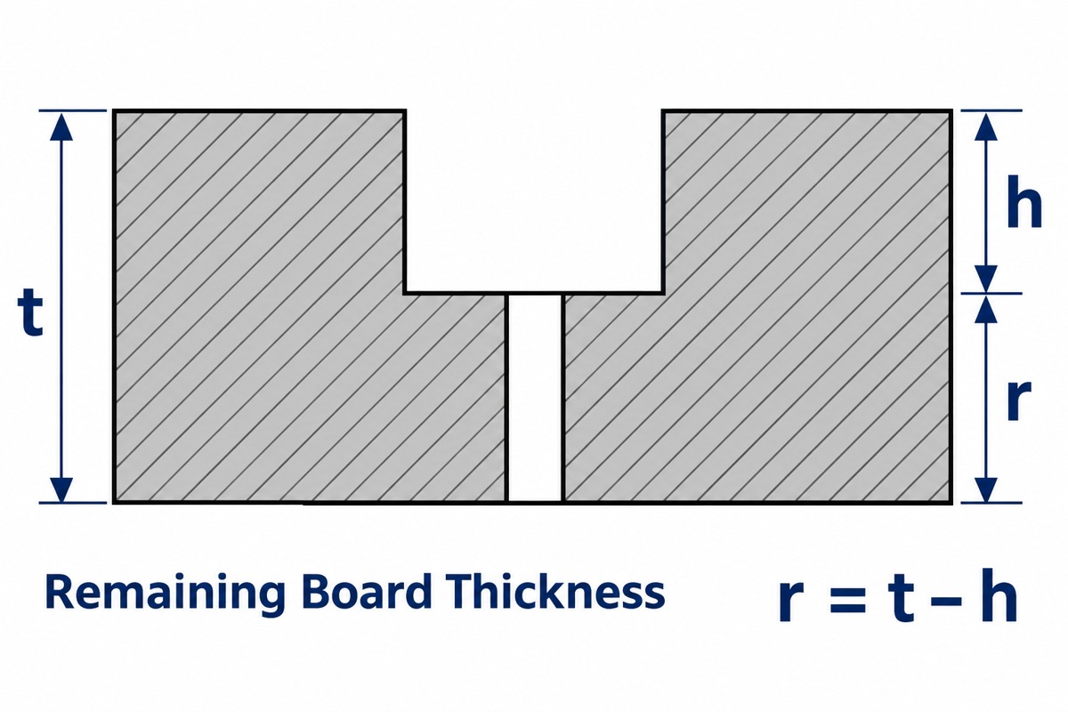
PCB section showing total thickness, recess depth and remaining material beneath the counterbore floor

How Should Copper Be Cleared Around a Counterbore?

Clear copper from the entire machined recess envelope on every layer the cut can reach, then add the project’s manufacturing and electrical clearance allowances. A keep-out around only the smaller through hole can leave copper exposed on the recess wall or floor.

Review the stackup in section, not just the top-layer layout. Include recess position and diameter tolerances, depth variation, internal-plane registration and the conductive hardware envelope. Solder mask should not be treated as the sole insulation between a clamped screw and a conductor.

  • Check internal planes as well as visible surface traces.
  • Define whether any copper contact is intentional for chassis grounding.
  • Keep nearby vias, pads and components outside the required machining and assembly envelope.
  • For metal-core boards, assess isolation from the exposed metal base separately.

The final clearance belongs in the approved design rules and fabrication drawing. Our PCB design guidance provides the broader design context; the recessed mounting detail still needs a project-specific stackup review.
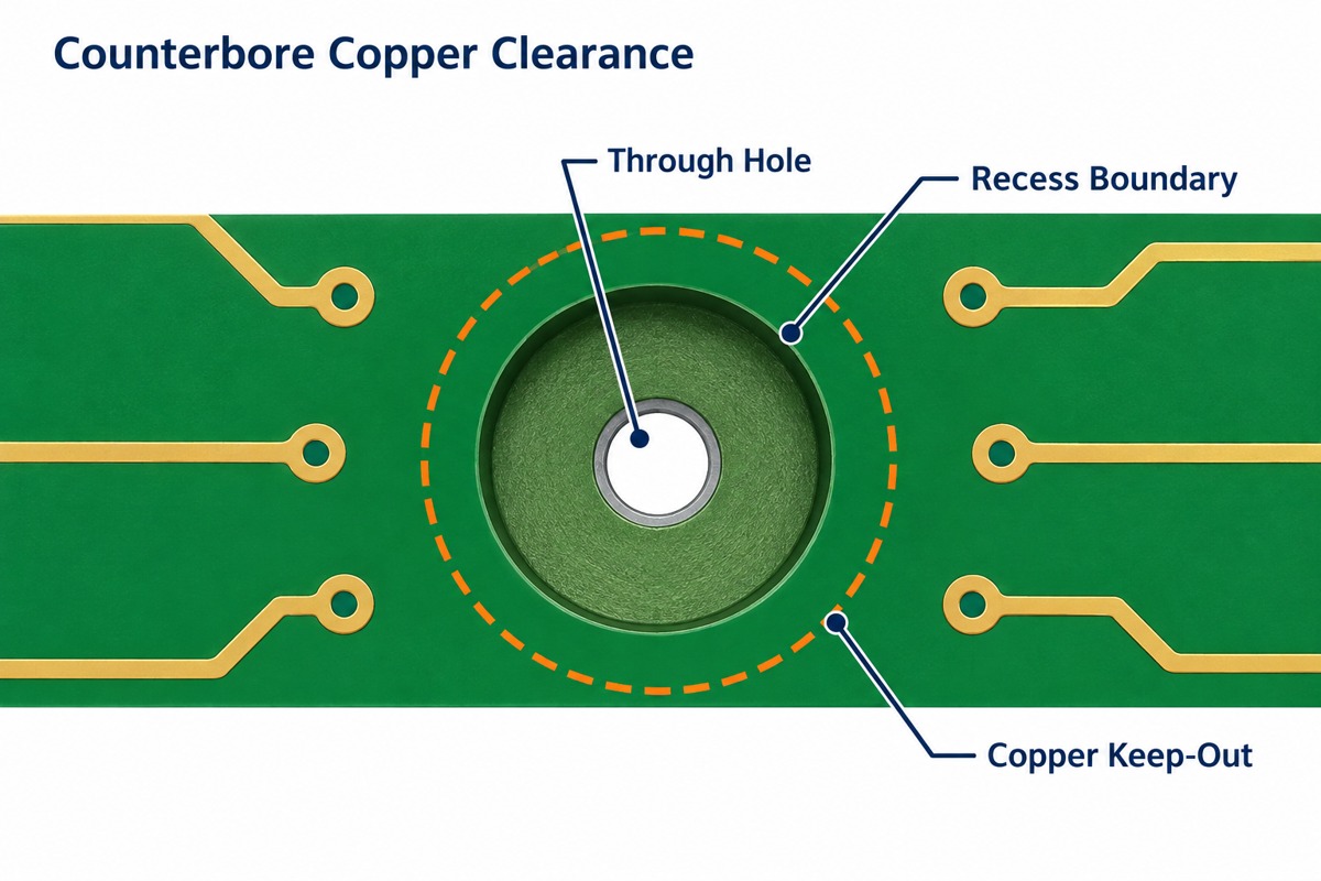
Top view showing copper clearance outside the full counterbore recess rather than only the smaller hole

Which Counterbore Tool Creates a Flat Bottom?

A purpose-made counterbore cutter or a suitable flat-bottom milling tool can form the recess. An ordinary pointed twist drill leaves a conical bottom and does not create the required flat annular bearing seat by itself.

A piloted counterbore tool uses the smaller hole to guide the cutter. CNC milling can instead locate the recess from the board’s reference system. Tool choice depends on material, diameter, depth, access and the required floor finish; metalworking speed-and-feed charts should not be copied directly to glass-reinforced PCB laminate.

For FR4, the process must address abrasive glass reinforcement, breakout and dust extraction. The fabrication drawing should specify the finished geometry and acceptance requirements, while the manufacturer selects a qualified machining method.

How Are Counterbores Made in PCBs?

PCB counterbores are made by controlled-depth machining at the specified hole locations, followed by cleaning and dimensional inspection. The fabricator determines the operation sequence relative to drilling, plating and other board processes.

  1. Review the detail: reconcile the mechanical drawing, stackup, drill data and fastener envelope.
  2. Establish the reference: identify the machining side, depth datum and location datum.
  3. Support the board: fixture the part so cutting loads do not bend or damage it.
  4. Machine the feature: control the larger recess diameter and floor depth using the approved toolpath.
  5. Clean and inspect: remove debris, check edges and measure the finished feature.

If the smaller bore must be plated, specify that requirement independently from the recess surfaces. Machining after plating can remove copper in the cut area; a drawing that merely says “plated hole” does not define the finished condition of every exposed surface.

What Should Counterbore Inspection Check?

Inspection should verify recess diameter, depth, location and floor condition, then confirm that the specified hardware seats correctly. A screw fitting into the hole does not prove that sufficient laminate or copper clearance remains.

Feature Inspection approach
Diameter and relative position Optical or dimensional measurement against drawing datums
Recess depth Depth measurement from the specified surface to the annular floor
Floor and edges Magnified inspection for burrs, raised fibers, damage and uneven seating
Fastener fit Specified screw and washer checked for interference and installed height
Hidden layer relationship Stackup review; agreed sectioning or additional verification where needed

A depth-gauge probe must contact the recess floor, not fall into the central through hole. Agree the measurement method before production when the annular seat is narrow or the top surface has features that affect the reference.
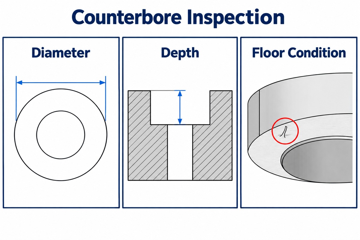
Counterbore inspection concepts showing diameter measurement, recess depth and floor condition

What Causes Counterbore Assembly Problems?

Incorrect depth, insufficient diameter, hole offset and damaged bearing surfaces are common causes of poor seating. Identify the physical interference before enlarging or deepening the recess.

  • Head stands proud: check actual head height, washer thickness and shallowest recess depth.
  • Screw enters but will not seat: check the under-head fillet, burrs and small-hole edge geometry.
  • Head rubs one side: check positional offset and minimum radial clearance.
  • Board cracks during tightening: review remaining thickness, backing support and the assembly torque specification.
  • Electrical contact appears after assembly: inspect exposed copper, metal-core contact and the hardware clearance envelope.

Do not correct a seating problem by tightening harder. Rework that changes recess depth or exposes a new layer needs engineering approval and renewed inspection.

When Is a Countersink or Spotface More Appropriate?

A countersink is appropriate for a matching conical flat-head screw; a spotface is appropriate when only a flat bearing surface is needed. Neither is a universal replacement for a counterbore in a thin PCB.

A countersink still removes material and must match the screw’s included angle. A spotface normally leaves the head above the surrounding surface, so it will not solve a requirement for full head recessing. For a wider comparison of the hole types and hardware, see our counterbore vs countersink guide.

FAQ About Counterbores

Does counterbore depth include the through hole?

No. It measures from the specified entry surface to the floor of the larger recess. Through-hole depth or the THRU designation is a separate requirement.

Is a counterbore hole threaded?

The enlarged recess normally provides clearance for hardware, not thread engagement. A smaller bore may be threaded in a mechanical component, but ordinary PCB mounting holes usually pass the screw to a nut, standoff or threaded enclosure.

Can the same counterbore fit every M3 screw?

No. M3 identifies the nominal thread diameter, not one head shape or height. Socket-head, low-head and button-head screws require different envelope checks. Washers can also change the required diameter and depth.

Is counterboring the same as backdrilling a PCB?

No. Counterboring creates a mechanical recess, usually for hardware. PCB backdrilling removes an unwanted plated via stub for electrical performance. Their purposes, depth targets and acceptance criteria are different.

Are Gerber files enough to specify a counterbore?

Not reliably on their own. Provide a dimensioned mechanical drawing with a section view, depth, machining side and tolerances, together with drill data and the stackup. Reconcile any differences between the drawing and manufacturing files before release.

Need a PCB Counterbore Reviewed Before Fabrication?

At EBest Circuit, we can review the recessed-hole detail alongside your FR4 board design and manufacturing files. Our PCB and PCB assembly services let you address fabrication geometry and final hardware access within the same project.

Send Gerber files, drill data, the board stackup, a dimensioned counterbore drawing, the screw or washer specification and quantities to sales@bestpcbs.com. Include any insulation, grounding or mechanical-load requirements so we can assess the feature before quoting.
You may also like

Reliable Counterbore vs Countersink PCB Design
Friday, January 9th, 2026

Counterbore vs countersink refers to two distinct machining processes for creating recessed holes, critical for component seating and fastener flush-mounting in PCB assemblies. This article provides a comprehensive guide to their design, symbols, applications, and how partnering with a specialist manufacturer ensures reliability in your PCB projects.

Choosing the wrong recessed hole type often leads to avoidable design errors, assembly delays, and reliability risks later in the PCB lifecycle.

  • Drawing Confusion: Misreading countersink symbol or counterbore symbol on fabrication drawings
  • Incorrect Fit: Wrong hole type or dimensions prevent screws from sitting flush
  • Cost Overruns: Overusing counterbore machining when a countersink is sufficient
  • Assembly Errors: Poorly defined counterbore hole or countersink geometry disrupts SMT or mechanical assembly
  • Reliability Risks: Mismatched fasteners (counterbore vs countersink screws) weaken joints or damage boards

How can a professional PCB partner resolve these issues?

  • DFM & Drawing Support: Correct use of counterbore and countersink symbols per standards (ASME Y14.5)
  • Precision Machining: Tight control of counterbore hole dimensions and countersink angles
  • Cost-Driven Design Advice: Clear guidance on countersink vs counterbore advantages
  • Assembly-First Engineering: Hole designs optimized for SMT and mechanical assembly
  • Material Expertise: Proper counterbore tool and process selection for FR-4, ceramic, and specialty substrates

At EBest Circuit (Best Technology), we are a professional PCB and assembly manufacturer specializing in complex, high-precision board fabrication. Our core strength lies in transforming intricate designs—especially those requiring precise counterbore and countersink​ features—into reliable, high-performance assemblies. Trust us to navigate the details so your design excels. Pls feel free to contact us at sales@bestpcbs.com​ for your next printed circuit board or SMT PCB manufacturing project.

 Counterbore vs Countersink

What Is Counterbore vs Countersink?

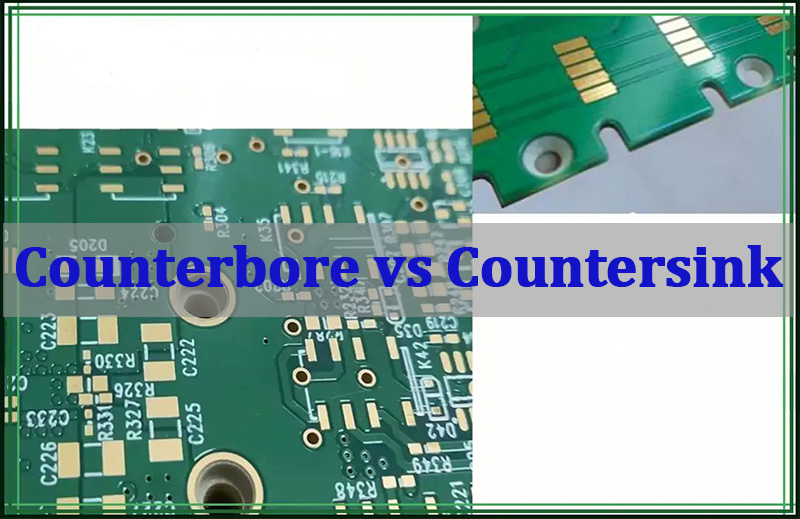
In PCB design and mechanical assembly, counterbore vs countersink​ describes two methods for creating a recess around a drilled hole. The fundamental difference between counterbore and countersink​ lies in their geometry and purpose.

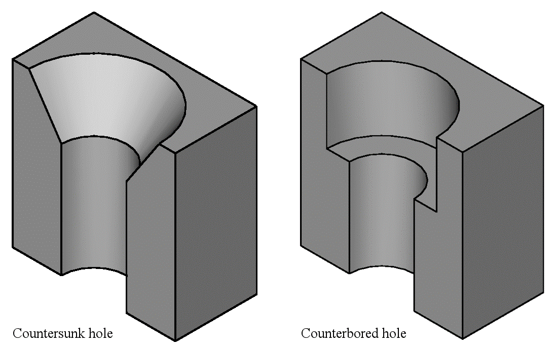
  • Countersink:​ A conical-shaped recess cut into the material. Its primary goal is to allow a conical screw head (e.g., flat head) to sit flush with or below the surface.
  • Counterbore:​ A cylindrical, flat-bottomed recess cut into the material. It is designed to allow a bolt head or hex-head fastener to sit below the surface, often topped with a fillister or cap.
FeatureCountersinkCounterbore
Shape​ConicalCylindrical
Purpose​Flush-mount conical screwsSeat bolt heads below surface
Bottom​Tapers to a pointFlat
Typical Fastener​Flat-head screwSocket-head cap screw

Understanding this counterbore vs countersink hole​ distinction is the first step toward reliable design. Choosing correctly ensures proper component seating, avoids interference, and contributes to a professional finish.

Counterbore vs Countersink

Understanding Counterbore Hole Geometry and Typical Dimensions

A counterbore hole​ is defined by specific, measurable parameters crucial for fabrication. Unlike a tapering countersink, its cylindrical nature demands precise control.

Key dimensions for a counterbore hole​ include:

  • Through-Hole Diameter:​ The diameter of the primary pilot hole for the fastener shaft.
  • Counterbore Diameter:​ The larger diameter of the recess, which must accommodate the fastener head.
  • Counterbore Depth:​ The depth of the recess, controlling how far the head sits below the surface.
  • Tolerance:​ Critical for fit; tight tolerances (e.g., ±0.05mm) prevent fastener wobble or binding.
  • Corner Condition:​ A sharp corner vs. a small radius can affect stress concentration and tool selection.

Proper specification prevents issues—a depth too shallow leaves the head protruding, while a diameter too small makes assembly impossible. For reliable PCB design and SMT services, communicating these dimensions clearly is non-negotiable.

How to Read Countersink Symbol and Counterbore Symbol on Engineering Drawings?

Engineering drawings use standardized symbols to convey counterbore and countersink​ requirements efficiently, eliminating textual ambiguity. Misreading these is a common source of fabrication errors.

  • Countersink Symbol:​ Often represented by a ‘V’ shape drawn over the hole leader line. The callout typically specifies the diameter at the surface (or the included angle) and the angle itself (e.g., ∅6.0 X 82°).
  • Counterbore Symbol:​ Usually represented by a square ‘⌴’ shape drawn over the hole leader line. The callout specifies the counterbore hole dimensions: diameter and depth (e.g., ∅8.0 X 3.2 DEEP).
SymbolShapeCallout ExampleMeaning
Countersink​‘V’∅6.0 X 82°Machine a 82° cone to a 6.0mm top diameter.
Counterbore​‘⌴’∅8.0 X 3.2 DEEPMachine a cylindrical recess 8.0mm in diameter and 3.2mm deep.

Mastering these counterbore vs countersink symbols​ ensures your design intent is communicated flawlessly to the manufacturer, a cornerstone of reliable PCB design.

Countersink vs Counterbore Advantages

The advantages of countersink vs counterbore​ guide the selection process. Each offers benefits suited to different applications.

  • Countersink Advantages:
    1. Flush Surface:​ Creates a completely smooth, uninterrupted surface ideal for sliding parts or aesthetic finishes.
    2. Self-Centering:​ The conical shape can help guide the screw head into place during assembly.
    3. Material Efficiency:​ Often removes less material than a counterbore, which can be beneficial for thin substrates.
    4. Wide Availability:​ Standardized angles (82°, 90°, 100°) and tools are readily available.
  • Counterbore Advantages:
    1. Precise Head Seating:​ Flat bottom provides positive, stable seating for bolt heads, offering excellent counterbore vs countersink strength​ in shear applications.
    2. Space for a Washer:​ The cylindrical recess can accommodate a washer under the fastener head.
    3. Cleaner for Hex/Allen Keys:​ Provides unobstructed access for tools to drive socket-head fasteners.
    4. Easier to Measure:​ Cylindrical dimensions are simpler to verify with standard pin gauges or micrometers than conical angles.

Choosing based on these countersink vs counterbore advantages​ directly impacts the functionality and manufacturability of your assembly.

 Counterbore vs Countersink

Counterbore vs Countersink Screws: Which Fasteners Work with Each Hole Type

The hole type is dictated by the fastener. Using the wrong pairing is a guaranteed assembly failure.

  • Fasteners for Countersinks:​ Designed for conical recesses.
    • Flat Head Screws:​ The most common type, with a head angle (e.g., 82°) matching the countersink angle.
    • Oval or Raised Countersunk Heads:​ Provide a decorative finish while still sitting within the conical recess.
  • Fasteners for Counterbores:​ Designed for cylindrical recesses.
    • Socket Head Cap Screws (Allen Bolts):​ The standard choice, with a cylindrical head and flat bottom.
    • Button Head or Flat Socket Head Screws:​ Offer a lower profile within the counterbore hole.
    • Hex Bolts with Washers:​ The counterbore​ depth must account for both the head and washer thickness.

The rule is absolute: a conical screw requires a countersink; a cylindrical-headed bolt requires a counterbore. This compatibility is vital for reliable SMT services​ that include mechanical mounting.

Counterbore vs Countersink vs Spotface: How These Hole Types Differ in Practice

While counterbore and countersink​ are common, spotfacing​ is a related operation. Understanding counterbore vs countersink vs spotface​ prevents specification errors.

  • Spotface:​ A very shallow counterbore. Its primary purpose is not to recess a fastener head but to create a flat, smooth, and perpendicular seating surface on an otherwise rough or uneven workpiece (e.g., on a casting). The depth is minimal, just enough to clean up the surface.
  • Key Difference:​ A spotface​ is about creating a finishand squaresurface; a counterbore​ is about creating depthfor clearance. In PCB contexts, true spotfacing​ is rare; most recesses for fastener heads are counterbores.

Countersink vs Counterbore PCB Applications in Electronics Assembly

In PCB design and SMT services, these features are not just for mechanical enclosures but are integral to the board itself.

  • Countersink PCB Applications:
    • Mounting boards flush into tight chassis with flat-head screws.
    • Creating a smooth surface behind a display or touch panel.
    • Reducing snag points on wearable or handheld devices.
  • Counterbore PCB Applications:
    • Seating standoffs or spacer nuts below the board surface.
    • Providing clearance for the heads of screws that mount heatsinks or large components to the PCB.
    • Allowing a connector or module to sit flush over a mounting screw location.

These PCB applications​ highlight how counterbore and countersink​ features enable compact, robust, and professional electronic assemblies.

When To Use Countersink vs Counterbore?

The decision of when to use countersink vs counterbore​ follows a clear logic tree based on design requirements.

Use a COUNTERSINK when:

  • The fastener has a conical head (flat head screw).
  • A perfectly flush surface is mandatory.
  • The application is primarily tensile (clamping force along the screw axis).

Use a COUNTERBORE when:

  • The fastener has a cylindrical head (socket cap screw, hex bolt).
  • The fastener head must be below the surface but a flat seating is needed for strength.
  • You need tool clearance for an Allen key or hex driver.
  • A washer is used under the fastener head.

For reliable PCB design, this choice must be made early in the layout phase to accommodate the necessary space and layer clearance.

How Counterbore vs Countersink Decisions Impact PCB Manufacturing Accuracy?

The counterbore vs countersink​ choice directly affects manufacturability and cost. Precision is paramount.

  • Accuracy Challenges:
    • Countersink:​ Controlling the angleand the diameter at the surfaceis critical. A slight angle error prevents a flush fit.
    • Counterbore:​ Controlling the depthand the cylindrical diameteris critical. Depth errors cause heads to protrude or sink too deep.
  • Manufacturing Impact:​ Counterbores​ often require a tool change (a specific counterbore bit) after drilling the pilot hole, adding a process step. Countersinks​ may be done with a dedicated bit or a chamfering tool. Both processes demand stable, CNC-controlled equipment to maintain positional accuracy relative to SMT pads and traces.

A manufacturer’s capability to hold tight tolerances on these features is a direct indicator of their suitability for high-reliability PCB projects.

Why Engineers Choose Best Technology for Counterbore vs Countersink PCB Projects?

Engineers choose partners who eliminate risk. For projects demanding precision counterbore and countersink​ features, the choice involves several key considerations.

  • Technical Expertise:​ Deep understanding of counterbore vs countersink vs counter drill​ operations and their implications on different PCB materials.
  • Process Capability:​ Investment in precision drilling/milling machinery and inspection tools (optical comparators, CMM) to verify counterbore hole dimensions​ and countersink angles.
  • Design Partnership:​ Willingness to review countersink vs counterbore callouts​ and suggest optimizations for yield and cost as part of reliable SMT services.
  • Material Experience:​ Knowledge of how materials like FR-4, Rogers, or ceramic behave during machining to prevent delamination or cracking.
  • Full-Service Integration:​ Ability to not only fabricate the board with these features but also to handle the subsequent SMT and mechanical assembly, ensuring a perfect fit.
 Counterbore vs Countersink

In a nutshell, Counterbore vs countersink​ are essential machining techniques that enable secure, flush fastener installation and component seating in sophisticated PCB assemblies. Mastering their design, symbols, and applications is key to achieving reliable, professional-grade electronics.

For designers seeking a manufacturing partner that treats these critical details with the precision they deserve, EBest Circuit (Best Technology)​ stands ready. We combine extensive experience in complex PCB fabrication—including precise counterbore and countersink​ machining—with comprehensive SMT services​ to deliver fully realized, reliable products. Pls feel free to contact us anytime at sales@bestpcbs.com to discuss your next PCB project.

You may also like

Understanding Counterbore and Countersunk Holes in PCB Design
Saturday, July 8th, 2023

When we talking about the holes in PCBs (Printed Circuit Boards), may somebody always curious about two special holes: Counterbore hole and Countersunk hole. They are easy to be confused and easy to misunderstanding if you are a layman of PCB. Today, we will introduce the differences between counterbore and countersunk for details, let’s keep reading!

What is a Counterbore Hole?

A counterbore hole is a cylindrical recess on a PCB that has a larger diameter at the top surface and a smaller diameter at the bottom. The purpose of a counterbore hole is to create space for a screw head or a bolt’s flange, allowing it to sit flush with or slightly below the PCB surface. The larger diameter at the top accommodates the head or flange, while the smaller diameter ensures that the fastener’s shaft or body fits snugly.

What is a Countersunk Hole?

On the other hand, a countersunk hole is a conical recess on a PCB that allows the head of a screw or bolt to sit flush with the PCB surface. The shape of a countersunk hole matches the profile of the fastener’s head, creating a seamless and level surface when the screw or bolt is fully inserted. Countersunk holes typically have an angled side, often 82 or 90 degrees, which determines the shape and size of the fastener head that will fit into the recess.

Counterbore VS Countersunk: Geometry

While both counterbore and countersunk holes serve the purpose of accommodating fasteners, their main difference lies in their geometry and the types of fasteners they accommodate.

Counterbore holes have a cylindrical recess with two different diameters, while countersunk holes have a conical recess with a single diameter.

Counterbore holes create a stepped or raised region on the PCB surface, whereas countersunk holes result in a flush or recessed surface.

Counterbore VS Countersunk: Fastener Types

Counterbore holes are primarily used for fasteners with a head or flange, such as bolts or screws that require a solid mounting surface.

Countersunk holes are designed for fasteners with a conical head, such as flathead screws or countersunk bolts, to achieve a flush surface.

Counterbore VS Countersunk: Drill angles

Different sizes and drilling angles of drill bits are offered for producing countersinks, depending on the intended use. These angles can include 120°, 110°, 100°, 90°, 82°, and 60°. However, the most frequently employed drilling angles for countersinking are 82° and 90°. For optimal outcomes, it is essential to align the countersink angle with the tapered angle on the underside of the fastener head. On the other hand, counterbore holes feature parallel sides and do not necessitate tapering.

Counterbore VS Countersunk: Applications

The choice between counterbore and countersunk holes depends on the specific requirements of the PCB design and the components being used.

Counterbore holes find applications in situations where a secure and flush fastening of components or mounting plates is necessary. They are commonly used to fasten connectors, brackets, or PCBs to an enclosure or chassis.

Countersunk holes are often employed when aesthetic considerations are important, as they provide a sleek and level surface. They are frequently used for mounting PCBs to surfaces where a flush finish is desired, such as in consumer electronics or decorative applications.

Counterbore and countersunk holes are important features in PCB design, enabling efficient component mounting and secure fastening. Understanding the differences between these two types of holes allows designers to select the appropriate option based on the specific requirements of their circuit board applications. Whether it’s ensuring a secure connection or achieving a visually pleasing finish, the choice between counterbore and countersunk holes plays a crucial role in the overall functionality and aesthetics of a PCB assembly.

You may also like