A fuse symbol marks a protective device that opens a circuit when excessive current melts its fuse element. Reading it correctly involves more than recognizing the shape: the nearby reference number, rating, and circuit connections explain which fuse it is and what it protects.
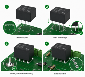
At EBest Circuit, we support PCB fabrication, component sourcing, and SMT or through-hole assembly from your approved design. Matching the specified fuse to its PCB footprint and assembly documentation helps prevent component mismatches during production. For PCB and PCBA project support, contact sales@bestpcbs.com.
What Does a Fuse Symbol Look Like?
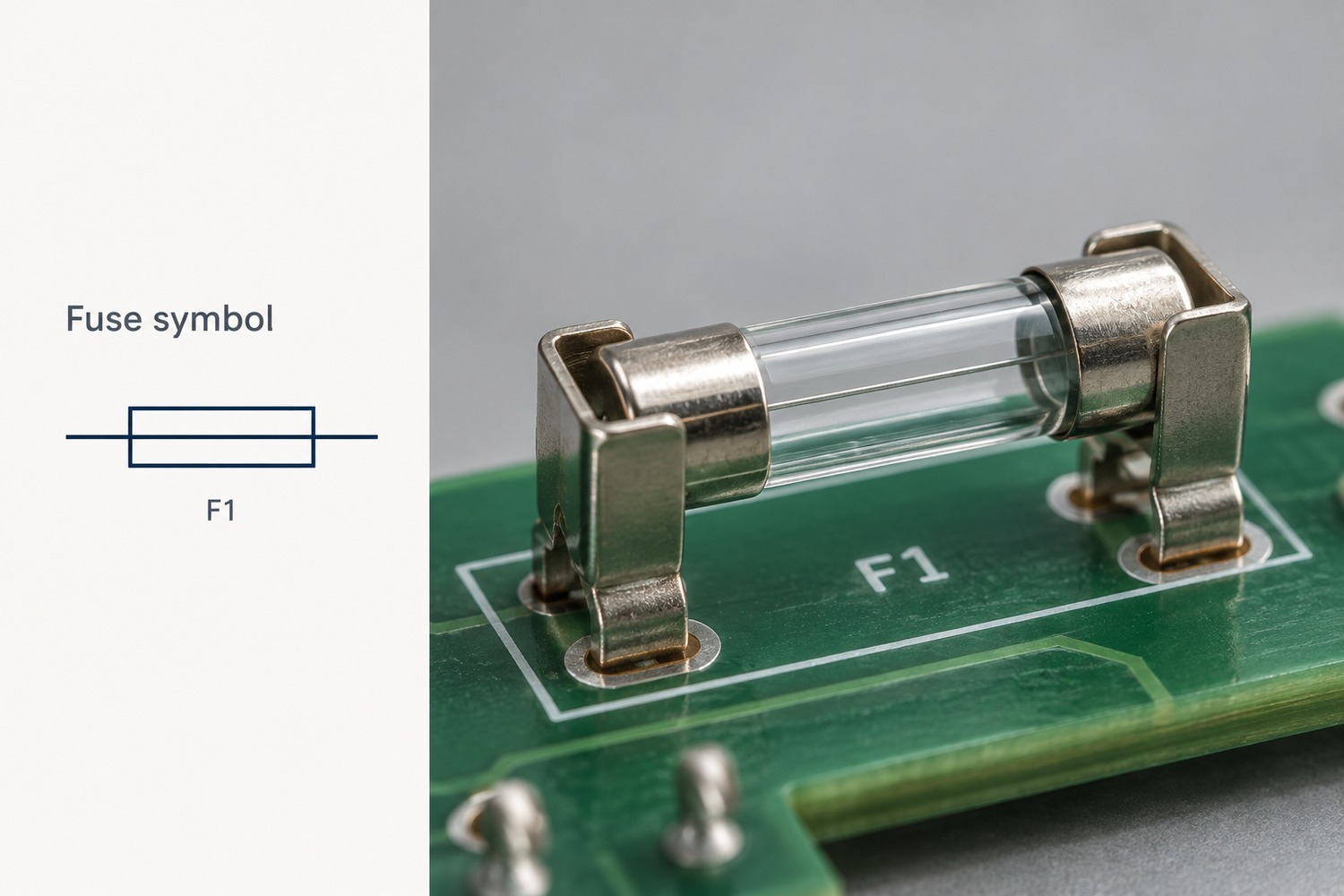
A common fuse symbol is a small rectangle with a straight line running through its center. Another familiar form uses a short curved or S-shaped element between the connecting wires. Both represent a fuse rather than its physical package.
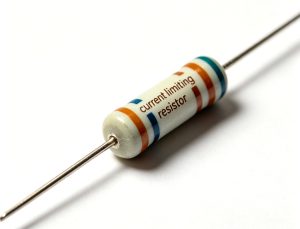
The rectangle can resemble an IEC resistor symbol. The useful distinction is that the common rectangular fuse symbol has a line through the box, while the basic rectangular resistor symbol does not. Nearby identifiers also help: F1 commonly identifies a fuse; R1 identifies a resistor.
A curved fuse element can also resemble other symbols in a small drawing. Read the graphic together with its identifier and the drawing legend, rather than relying on the outline alone.
Why Do Fuse Symbols Look Different Across Diagrams?
Drawing standards, symbol libraries, and the amount of detail shown can all change a fuse’s appearance. IEC 60617 and IEEE/ANSI conventions are common references, but their implementations can overlap.
Difference in the drawing
What it means
Rectangle with a center line or a curved element
Alternative representations encountered in different drawing conventions
Horizontal or vertical orientation
The symbol has been rotated to fit the circuit layout
Added striker or alarm-contact detail
The fuse assembly includes an indication or actuation feature
A rectangle alone does not establish whether the entire drawing follows IEC or IEEE conventions. Both IEC and IEEE symbol libraries can contain the rectangular center-line form. Likewise, a different symbol shape does not automatically mean a different current rating or operating speed.
What Do the Markings Beside a Fuse Symbol Mean?
The reference designator identifies the component; the specification describes its electrical characteristics. For example, F1 means a particular fuse in the design, not a 1-amp fuse.
Consider a fuse identified as F1, with the specification T3.15AL250V. In the miniature-fuse marking convention used for this example:
Marking
Meaning
F1
Component reference, used to connect the schematic, BOM, and assembly drawing
T
Time-delay characteristic
3.15A
Rated current of 3.15 amperes
L
Low breaking-capacity category
250V
Rated voltage of 250 volts
The rated current and breaking capacity describe different things. Rated current concerns normal current carrying; breaking capacity concerns safely interrupting a fault current. The letter L does not provide the complete numerical interrupting rating.
Similarly, 250V is not a voltage at which the fuse automatically blows. The applicable AC or DC rating comes from the device specification. This marking format is not universal for all fuse packages, particularly small surface-mount parts with manufacturer-specific codes.
How Are Fast-Blow and Slow-Blow Fuses Identified on Schematics?
The basic fuse symbol often stays the same; the accompanying value, note, or part number identifies the operating characteristic. In common miniature-fuse markings, F indicates fast-acting and T indicates time-delay.
Fast-blow fuse: Intended to interrupt overcurrent without the intentional surge tolerance of a time-delay design. It still takes time to operate.
Slow-blow fuse: Designed to withstand specified brief current surges, such as those associated with startup, while providing overcurrent protection.
For example, F2A and T2A both indicate a 2A current rating in this marking system, but their time-current behavior differs. They should not be treated as interchangeable solely because the current rating matches.
Also distinguish the F in F1, which identifies the component, from the F in F2A, which describes its speed. The manufacturer’s time-current curve defines the response more precisely than either the symbol or the word “fast.”
How Do You Read a Fuse Circuit Diagram?
Follow the current path through the fuse to the load and back to the supply. A fuse protecting a branch is connected in series with that branch, so the branch current passes through its element.
For a simple 12V DC circuit, the path is:
Supply +12V → F1 → Load → Supply return (0V)
This example shows three useful relationships:
Normal operation: F1 conducts the load current and completes the supply path.
Downstream fault: A short circuit can increase the current through F1. Whether and how quickly it opens depends on the available fault current and fuse characteristics.
After F1 opens: The load loses this supply path. The section between the source and F1 can remain energized.
If another branch connects to the supply before F1, that branch is outside F1’s protection path. This is why the connection points matter more than how close the fuse appears to a component on the page.
How Does a Fuse Symbol Relate to the Actual Component?
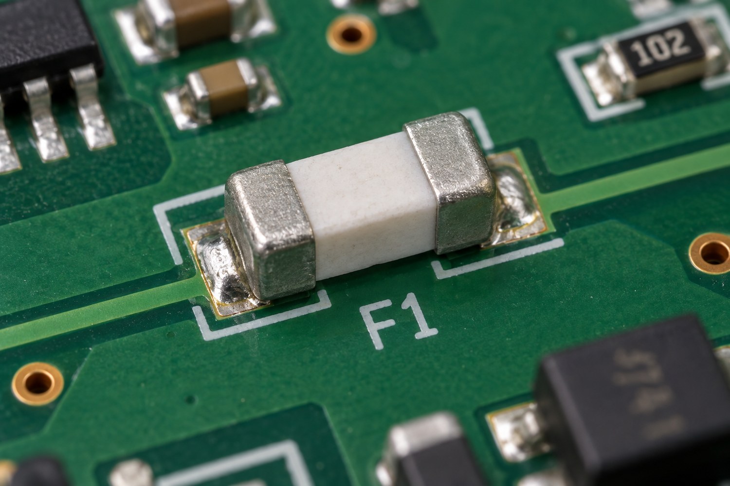
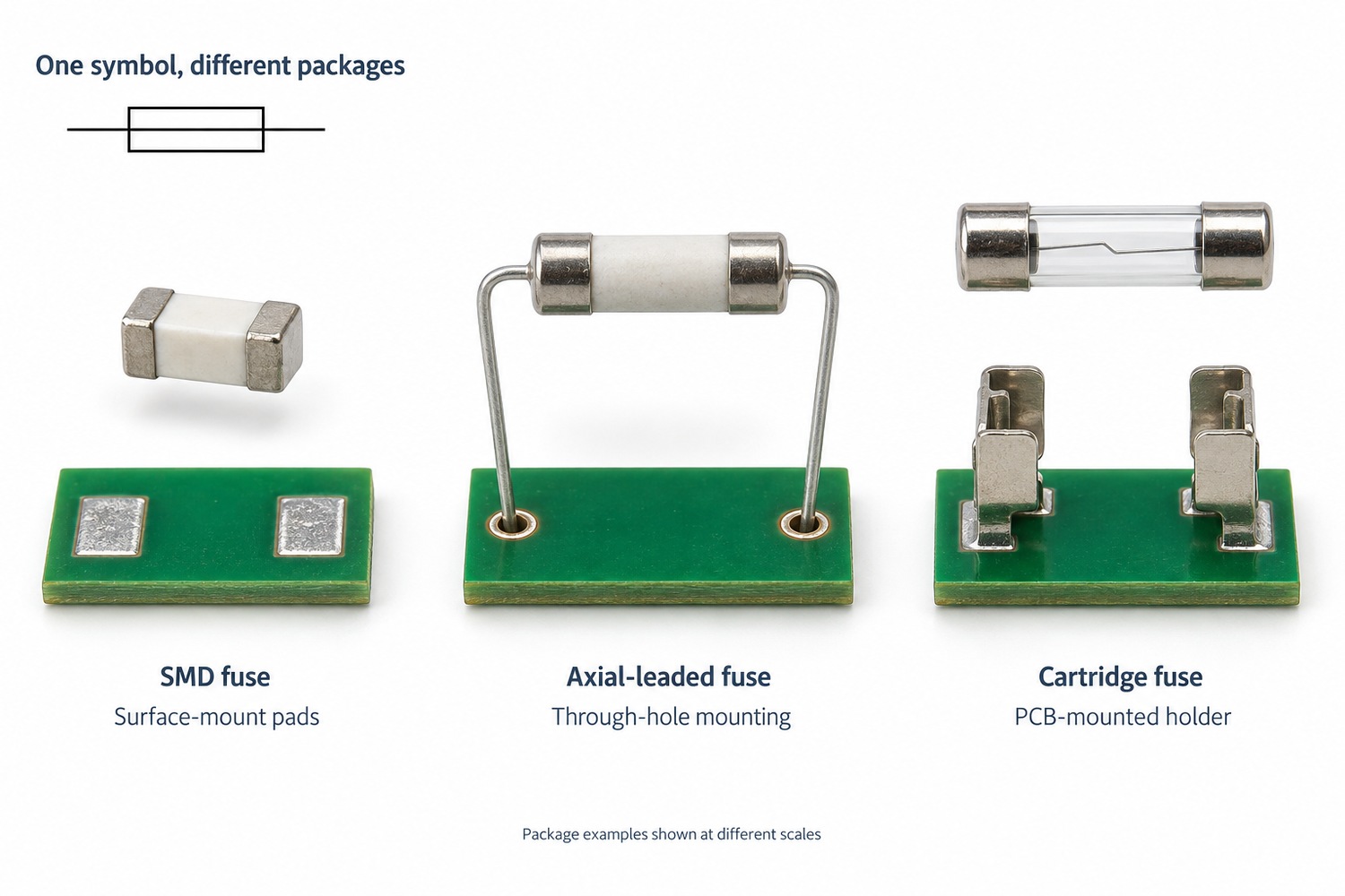
One basic schematic symbol can represent several physical fuse packages. It may correspond to a small SMD chip, a leaded fuse, or a cartridge fitted into a holder.
For a cartridge fuse, the PCB may carry the holder, while the replaceable fuse sits inside it. The board footprint must therefore match the holder’s terminals and dimensions.
Changing to another fuse with the same current rating may still require a different footprint, holder, or assembly process. The symbol alone does not establish mechanical compatibility.
Does a Fuse Symbol Show Whether the Fuse Has Blown?
An ordinary schematic fuse symbol does not report the fuse’s present condition. It identifies the device and its connection in the intended circuit.
A fault-analysis drawing may explicitly show an open fuse, while another drawing may include a fuse-operated alarm contact. Those details need to be interpreted through the drawing notes or legend; they are not live status indications by themselves.
The physical fuse’s condition requires inspection or measurement. For a conventional fuse, continuity testing is performed with power disconnected and stored energy discharged. Parallel circuit paths can produce a misleading reading, so isolation may be necessary. A printed symbol or an intact-looking fuse body is not sufficient evidence that the fuse is working.
FAQs About Fuse Symbols
Do AC and DC fuses use different symbols?
The basic symbol can be the same. AC and DC suitability is established by the specified fuse’s ratings, not by its symbol alone. An AC voltage rating does not automatically establish an equivalent DC rating.
How is a thermal fuse different from an ordinary fuse?
A thermal fuse opens at a specified temperature, while an ordinary overcurrent fuse responds to heating caused by current through its element. Thermal-fuse drawings may include a temperature notation or a distinct library symbol. Its electrical ratings still matter.
Is a resettable PTC the same as a fuse?
No. A resettable PTC increases its resistance when it trips, limiting current rather than creating the permanent open circuit of a melted fuse element. It can recover after the fault is removed and it cools, subject to the device’s operating conditions.
Does an SMD fuse need a special schematic symbol?
Usually, the basic fuse symbol is sufficient. The BOM and footprint distinguish an SMD package from a leaded or cartridge version. A tiny code printed on the component may be a manufacturer-specific rating code.
Are car fuse-box icons the same as schematic fuse symbols?
Not necessarily. A fuse-box cover may use icons to identify the protected function, such as lighting or a power outlet. A schematic fuse symbol identifies the protective device within the electrical circuit. The vehicle’s legend explains its particular icons.
For a PCB assembly project, the fuse symbol, specified part, and physical footprint should describe the same intended device. EBest Circuit can support fabrication, sourcing, and assembly from your approved files. Discuss your next build with us at sales@bestpcbs.com.
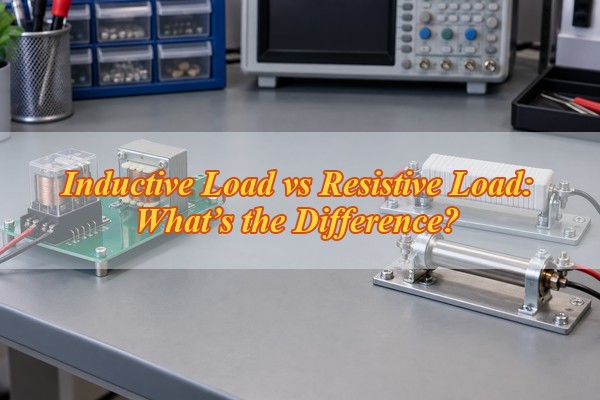
The main difference in an inductive load vs resistive load comparison is what happens to electrical energy. A resistive load uses the energy as it arrives, mainly as heat or light. An inductive load stores part of it in a magnetic field, so current builds more slowly, lags voltage in AC operation, and must keep flowing briefly when the circuit is switched off.
For a designer or buyer, that distinction changes real decisions: how much current the source must deliver, which relay or MOSFET rating applies, whether a turn-off clamp is needed, and how the high-current loop should be routed on the PCB. The sections below move from identifying the load to checking its waveforms, choosing a switch, controlling the transient, and specifying the parts needed for a reliable build.
What Is a Resistive Load?
A resistive load is one in which resistance dominates, so current follows the applied voltage with little phase shift. This makes its steady-state current comparatively easy to calculate, but temperature and startup conditions can still change the result.
For an ideal resistor, current follows Ohm’s law:
I = V / R
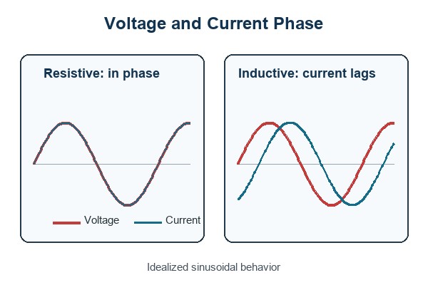
If voltage rises while resistance remains constant, current rises in the same proportion. With a sinusoidal AC supply, voltage and current cross zero and reach their peaks at nearly the same time. The phase angle is therefore close to 0°, and the displacement power factor is close to 1.
Heating elements, power resistors, and resistive load banks are common examples. An incandescent lamp is mostly resistive after it warms up, but its cold filament resistance is much lower than its operating resistance. It can therefore draw substantial inrush even though it is not an inductive load.
Treat “resistive” as the dominant operating behavior, not a promise that current never changes. Once that distinction is clear, the different behavior of a coil is easier to see.
What Is an Inductive Load?
An inductive load uses a winding or coil to create a magnetic field, and that stored magnetic energy resists rapid changes in current. The current therefore rises over time at turn-on and needs a discharge path at turn-off.
Motors, transformers, relay coils, solenoids, contactor coils, and electromagnetic actuators all contain significant inductance. With sinusoidal AC, current in an ideal inductor lags voltage by 90°. A real coil also has winding resistance, core loss, leakage inductance, and parasitic capacitance, so its actual phase angle is smaller and changes with frequency and operating point.
This behavior matters most during startup, PWM control, faults, and switch-off. A motor may draw high current before back EMF develops, while an energized relay or solenoid can generate a high voltage when its current path is interrupted.
If magnetic energy affects current rise, phase, or turn-off stress, the circuit must be designed as an inductive-load circuit. The next comparison shows how that changes the electrical requirements.
What Is the Difference Between Inductive and Resistive Loads?
In an inductive load vs resistive load comparison, a resistive load mainly dissipates energy, while an inductive load temporarily stores energy and can return it to the circuit. That one difference explains most of the changes in phase, power factor, switch rating, and transient protection.
The most useful comparison is not the label on the appliance, but the behavior seen at the interface you are designing:
Characteristic
Resistive load
Inductive load
Dominant property
Resistance
Inductance and winding resistance
AC phase
Current nearly in phase with voltage
Current lags voltage
Energy behavior
Mainly dissipates energy
Stores energy in a magnetic field
Power factor
Near 1 for an ideal linear load
Usually lagging and below 1
Switch-off response
No large magnetic-energy kick
Can generate a voltage transient
Typical examples
Heaters, power resistors, load banks
Motors, transformers, relays, solenoids
How Do Voltage and Current Behave in Resistive and Inductive Loads?
Voltage and current move together in a mainly resistive load, while an inductive load needs voltage to change its current. The difference appears as phase lag in steady-state AC and as a finite current rise or decay during switching.
For a linear inductor driven by a sinusoidal steady-state signal, the magnitude of inductive reactance is:
XL = 2πfL
Here, f is frequency in hertz, L is inductance in henries, and XL is measured in ohms. Higher frequency or higher inductance produces more opposition to AC current. A real coil also includes winding resistance, so its impedance and phase angle depend on both R and XL.
The formula is not a complete model for every condition. At DC steady state, an ideal inductor’s reactance is zero and the coil current is limited mainly by winding resistance. During turn-on or turn-off, the time-domain relationship V = L × di/dt is the relevant starting point. Saturation, core loss, and nonlinear drive electronics can further change the measured behavior.
Use XL = 2πfL for sinusoidal steady-state analysis, then check the time-domain waveform for switching stress. Those two views prevent a resistance-only measurement from hiding the important part of the load.
How Does Power Factor Differ Between Inductive and Resistive Loads?
An ideal resistive load has a power factor of 1, while a linear inductive load has a lagging power factor below 1. A lower power factor means the source and conductors may carry more RMS current for the same useful power.
Power factor is the ratio of real power to apparent power:
PF = P / S
For a single-phase sinusoidal load:
P = VRMS × IRMS × PF
At the same voltage and real power, reducing PF raises the RMS current. That increases conductor and connector loss, voltage drop, transformer loading, and thermal stress.
A low true-PF reading does not automatically prove that the load is inductive. Rectifier-capacitor inputs and other nonlinear electronics can have poor power factor because their current is distorted rather than simply phase-shifted. Compare true PF, displacement PF, current waveform, and circuit topology before choosing a correction method.
Power factor tells you how heavily the source is being used, but the waveform tells you why. That distinction matters when you move from a theoretical load to real equipment.
What Are Common Resistive and Inductive Load Examples?
Examples are useful only when they reveal the behavior the source or switch must handle. Many appliances contain several load types, so the internal circuit and operating mode matter more than a broad product category.
Typical resistive loads
Heating elements: Convert electrical energy into heat; their cold and hot resistance may differ.
Power resistors: Provide controlled dissipation for braking, biasing, balancing, or test loads.
Resistive load banks: Apply predictable real power to generators, UPS systems, and power supplies.
Incandescent filaments: Behave mainly as resistance when hot but can draw high cold-filament inrush.
Typical inductive loads
Motors: Use windings and magnetic fields; startup current depends on motor type, mechanical load, supply, and drive method.
Transformers: Draw magnetizing current and reflect the secondary load to the primary.
Relay and contactor coils: Store magnetic energy while energized and release it when switched off.
Solenoids and actuators: Convert magnetic force into motion and often require a controlled release time.
Refrigerators, air conditioners, pumps, and fans usually include motors, but the complete product may also contain heaters, capacitors, inverters, and switch-mode power supplies. Their input may be a mixed or nonlinear load even though one internal component is clearly inductive.
Use the example to find the likely behavior, then confirm it from the datasheet or measurement. The following checks turn that initial classification into usable design limits.
How Can You Check for Inductive Loads vs Resistive Loads?
The reliable way to identify a load is to combine circuit information, manufacturer data, and measurements at the real operating condition. No single clue is sufficient for sizing a switch or suppression network.
Inspect the circuit. Identify heaters, resistor networks, motors, transformers, relays, solenoids, and power-conversion stages. This establishes what behavior is plausible.
Read the device data. Look for PF, L/R time constant, coil resistance, inductance, locked-rotor current, inrush, switching category, or a separate inductive-load rating. Match the stated voltage and operating mode.
Measure voltage, current, and power. A power analyzer can show real power, apparent power, true PF, displacement PF, and waveform distortion. Lagging current supports an inductive classification; narrow current pulses point to nonlinear electronics.
Capture startup. A current probe can reveal motor or transformer inrush, but inrush by itself is not proof of inductance because cold lamps and capacitor-input supplies can also surge.
Capture turn-off. A correctly rated oscilloscope probe can show overshoot, ringing, and current-decay time. These measurements directly inform switch-voltage margin and clamp selection.
Repeat under worst conditions. Supply tolerance, temperature, mechanical load, PWM duty, cable length, and magnetic saturation can change the result.
For mains or other high-energy circuits, use appropriately rated instruments and qualified personnel. The goal is not merely to name the load; it is to establish the current, voltage, timing, and energy that the source and switch must survive.
A useful classification ends with measured limits, not just “inductive” or “resistive.” Those limits are what you need to select a switching device without relying on a misleading headline rating.
How Do Inductive and Resistive Loads Affect Switching Devices?
A switch rated for 10 A resistive service is not automatically safe at 10 A with a motor, relay coil, or solenoid. Inductive loads can add inrush, slower current interruption, contact arcing, semiconductor avalanche energy, and repetitive voltage stress.
For relays and contactors, use the manufacturer’s rating for the actual load category, voltage, current, power factor, or L/R time constant. The permissible current is often lower for an inductive-load condition because stored electromagnetic energy makes interruption more demanding. A large number printed on the relay may describe only a resistive test condition.
For MOSFETs, IGBTs, and smart switches, check nominal and startup current, repetitive pulse current, drain or collector voltage, safe operating area, clamp or avalanche energy, switching loss, junction temperature, and fault response. Verify the gate-drive conditions at the lowest drive voltage and worst temperature rather than assuming the typical curve represents the finished product.
Select the switch from the load-specific datasheet condition and the measured waveform—not from equal steady-state amperes. If the current cannot stop cleanly when the switch opens, the next design task is controlling where its stored energy goes.
Why Can Inductive Loads Produce Voltage Spikes When Switched Off?
The spike appears because an energized inductor’s current needs a path after the switch opens. If the circuit does not provide one, the voltage rises until current can flow through an unintended path.
The basic relationship is:
V = L × di/dt
A faster attempted change in current produces a larger induced voltage. The rising voltage may appear across a MOSFET, relay contact gap, wiring capacitance, connector, or insulation. It can lead to avalanche stress, contact arcing, EMI, logic resets, insulation damage, or gradual degradation that is not obvious during an initial bench test.
A mainly resistive load does not store comparable magnetic energy, so it normally lacks this large inductive kick. Parasitic inductance is still present in every current loop, however, and fast edge rates can create overshoot even with a nominally resistive load.
The practical question is not whether the spike exists, but where the current will flow and how high the voltage will rise. A deliberately chosen clamp answers both questions.
How Can You Protect a Circuit When Switching an Inductive Load?
A protection network must keep the switch voltage safe while letting the load release at the required speed. The best choice depends on AC or DC operation, stored energy, repetition rate, and the acceptable current-decay time.
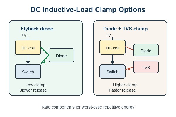
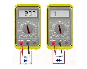
Flyback diode: Connect a diode reverse-biased across a DC relay or solenoid coil during normal operation. It provides a low-voltage current path at turn-off, but the slow decay can delay mechanical release.
Diode with Zener or TVS: A higher clamp voltage lets current fall faster. Check the switch voltage margin and the diode’s repetitive pulse energy at the maximum load current and temperature.
RC snubber: Use a resistor-capacitor network to reduce dv/dt, ringing, and contact arcing in a suitable AC or DC circuit. Choose values from the load and verify them on the measured waveform.
MOV: Use a metal-oxide varistor where its clamp voltage, surge energy, repetition rate, aging, and safety approvals match the application.
Integrated clamp or recirculation path: Confirm the driver’s allowable inductive energy, thermal duty, and demagnetization time. An internal clamp is not an unlimited energy sink.
A higher clamp voltage shortens current-discharge time, while a lower clamp voltage keeps the voltage down but extends the decay. This is why a simple flyback diode can be ideal for one coil yet too slow for a fast solenoid. A DC flyback diode must not be copied blindly across an AC coil, where it would conduct during one half-cycle.
Choose the clamp from voltage margin, energy, repetition, and release-time requirements together. Once the circuit is selected, PCB placement and routing determine whether that protection works at the switch.
What Should You Consider When Designing a PCB for Inductive Loads?
Design the PCB around peak current and the turn-off current loop, not just the coil’s steady-state current. Trace impedance, connector placement, and clamp location directly affect overshoot, EMI, and ground disturbance.
Current capacity: Size copper, vias, connectors, and terminals for startup, stall, PWM, and fault current where applicable.
Clamp location: Place the flyback diode, TVS, or snubber close to the load connector or switching path it protects. Long traces add inductance between the clamp and the switch.
Loop area: Keep the switch, load connection, clamp, and return path compact to reduce radiated and coupled noise.
Return path control: Keep load and clamp current out of sensitive analog, reference, and communication returns.
Switch margin: Check measured overshoot, pulse energy, SOA, gate drive, thermal impedance, and repetitive duty at worst supply and temperature.
Spacing and insulation: Set creepage, clearance, slots, coating, and connector spacing from the working voltage, expected transients, pollution degree, and applicable safety requirements.
Thermal path: Include conduction loss, switching loss, clamp dissipation, copper heating, and enclosure airflow.
Test access: Provide safe points for gate drive, switch node, current sense, and supply so startup and turn-off can be checked with the actual cable and load.
Before release, test minimum and maximum supply, relevant temperature extremes, the worst mechanical load, repeated switching duty, and the intended cable length. A stable running-current reading does not prove that the turn-off transient or thermal cycle is safe.
A robust PCB gives the stored energy a short, intentional path and leaves enough electrical and thermal margin for repetition. Those same requirements should appear in the BOM and sourcing package, not remain implicit in the schematic.
FAQs About Inductive and Resistive Loads
Q1: Is an electric heater always a purely resistive load?
A1: Usually it is predominantly resistive, but “purely” is too strong. A coiled heating element and its wiring have some parasitic inductance, and thermostats or electronic controllers can change the input waveform. For switch selection, use the heater’s cold resistance, rated current, and controller topology rather than assuming the hot-state wattage tells the whole story.
Q2: Why does a relay coil have both a resistance value and an inductance value?
A2: The wire contributes resistance, while the winding and magnetic core contribute inductance. Resistance largely sets the final DC coil current; inductance determines how quickly that current rises and falls. Both values are needed to understand drive current and release behavior.
Q3: Can a multimeter resistance reading tell whether a load is inductive?
A3: No. A resistance reading shows the DC resistance seen by the meter, but it does not reveal phase angle, saturation, inrush, or turn-off energy. Use the schematic or datasheet first, then measure current and switch-node voltage under the intended operating condition.
Q4: Should a flyback diode be added to a resistive heater controlled by a DC switch?
A4: Not simply because the load is switched. A flyback diode is intended to carry stored inductive current. A heater may still need protection for wiring inductance, controller transients, or a mixed load, but the correct device could instead be a TVS, snubber, or another network chosen from the measured transient.
Q5: Is a refrigerator an inductive load when sizing an inverter or generator?
A5: Its compressor motor makes startup capability important, but the appliance is a mixed load. Fans, heaters, controls, and an inverter drive may all contribute. Use the manufacturer’s input and surge data, or measure startup with the actual operating mode, rather than applying a generic motor multiplier.
Q6: Does power factor correction make an inductive load behave like a resistor?
A6: It can make the combined load look closer to unity power factor at the supply, but it does not remove the motor or transformer’s inductance. The winding still stores magnetic energy, so its startup, control, and switch-off requirements remain. Correction equipment must be sized for the actual operating range and harmonics rather than added as a generic capacitor.
Choosing the right relay, MOSFET, driver, diode, TVS, connector, and passive components is easier when the load behavior is defined before parts are ordered. Send EBest Circuit your BOM with exact manufacturer part numbers or approved alternatives, required quantities, target delivery date, and traceability or quality requirements for a component-sourcing quotation. If PCBA is included, add the schematic, Gerber or ODB++ files, load voltage and current, startup or stall current, switching frequency, clamp method, and test requirements. Email sales@bestpcbs.com to start the review.
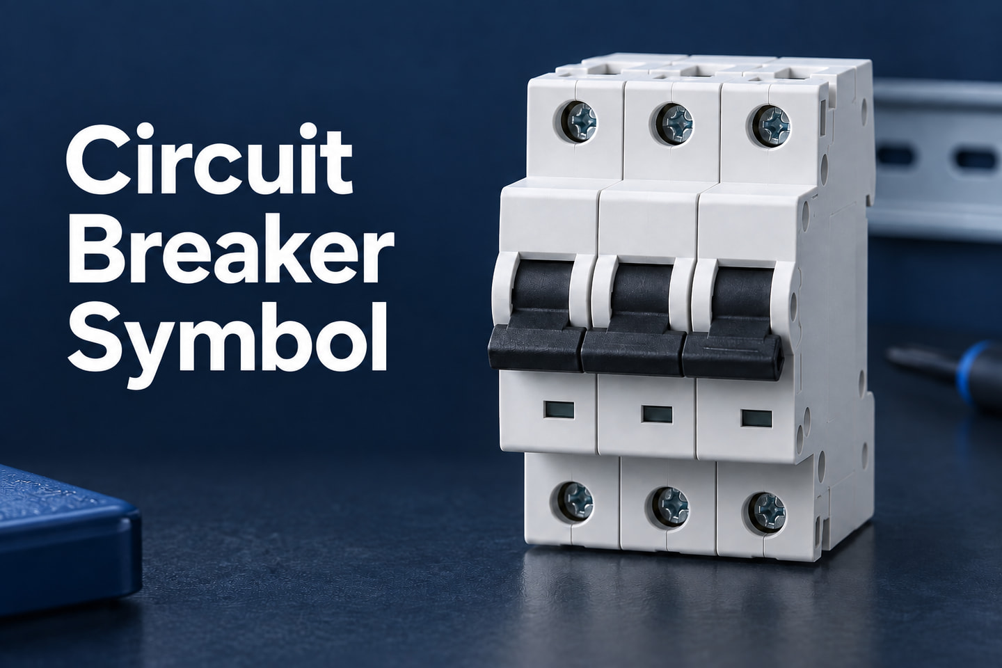
A circuit breaker symbol identifies a device that can interrupt a circuit and open automatically when its protection operates. On a drawing, it may resemble a switch contact with an added breaker mark, or appear as a compact device symbol on a single-line diagram. Reading it correctly means separating four things: the switching function, the number of poles, the protection shown, and the ratings written beside it.
This distinction matters when a power or control circuit moves from a schematic into physical hardware. A breaker symbol locates a protective device in the circuit, but it does not define a PCB footprint, terminal arrangement, or board layout. The following guide explains how to read the symbol and its surrounding information without assigning features the drawing does not show.
What Does a Circuit Breaker Symbol Look Like?
In a detailed schematic, look for a current path interrupted by a switching contact, together with a mark or designation identifying it as a circuit breaker. The contact may be drawn open, with a visible gap between the moving contact and its mating contact. That gap alone is not enough to distinguish a breaker from an ordinary switch.
In a power single-line diagram, the representation can be more compact. For example, some North American power drawings use a square containing the device number 52 for an AC circuit breaker. Here, the number identifies the device function; it is not a 52 A current rating.
Three parts of the drawing help establish what you are looking at:
The contact or device graphic locates the interruption point in the circuit.
The reference designation connects the symbol to a specific device in the drawing or equipment schedule.
The adjacent annotations supply details such as poles, rated current, or a trip-unit reference.
Read these together. An open contact marked as a circuit breaker is still a breaker, while an open contact without that identification could represent another switching device. Also check the drawing’s stated operating condition: a static schematic is not a live indication of whether the installed breaker is open or closed.
How Do IEC and ANSI Circuit Breaker Symbols Differ?
IEC and ANSI-style drawings can represent the same protective function with different graphics. The difference also depends on whether you are reading a detailed control schematic or a power single-line diagram. Comparing symbols without identifying the drawing type can make equivalent devices look unrelated.
IEC 60617 provides graphical symbols for diagrams. Detailed representations can combine contacts with qualifiers for the device or its operating mechanism. A simplified diagram may leave out mechanism details that appear elsewhere in the documentation.
North American drawings may use ANSI/IEEE conventions and device numbers. The square containing 52 is a useful example for AC power circuit breakers, but it is not the only breaker representation found in North American drawings. Detailed schematics and industrial control drawings can use different contact-based representations.
Use the drawing legend to establish the symbol family before interpreting a small mark. Do not apply the shortcut that every IEC breaker is a rectangle or every ANSI breaker has one fixed shape. An enclosure outline, a device function symbol, and a contact symbol do different jobs.
When comparing two drawings, match the device function, pole count, and protective operation first. Then compare the graphics. This avoids treating a change in drawing convention as a change in electrical function.
How Can You Tell a Circuit Breaker from a Fuse or Switch?
All three can interrupt current, but they do so in different ways. Their symbols should be compared within the same drawing convention.
Device
What to identify on the drawing
What distinguishes its operation
Circuit breaker
A breaker-specific contact or device symbol, supported by its designation and protection information
Its trip mechanism can open the contacts automatically when the relevant protection operates
Fuse
A fuse element represented in the current path; an IEC-style fuse commonly uses a small rectangle with the conductor passing through it
The element melts to interrupt overcurrent and must be replaced after operation
Ordinary switch
A switching contact without a breaker or fuse function identified
It opens or closes the circuit through its operating mechanism; the switch symbol alone does not indicate automatic overcurrent protection
The easiest mistake is to see an angled contact line and call it a breaker. That line primarily tells you about switching. The additional symbol detail and device identification establish whether protection is included.
A combined device needs closer reading. A switch-fuse assembly includes both switching and fuse protection; it should not be interpreted as a resettable circuit breaker simply because it can disconnect the supply.
For other components surrounding the protective device, consistent use of electrical and electronic symbols helps you follow the complete circuit without confusing a contact, a terminal, and a protective element.
3 Phase Circuit Breaker Symbol: What Do the Linked Contacts Mean?
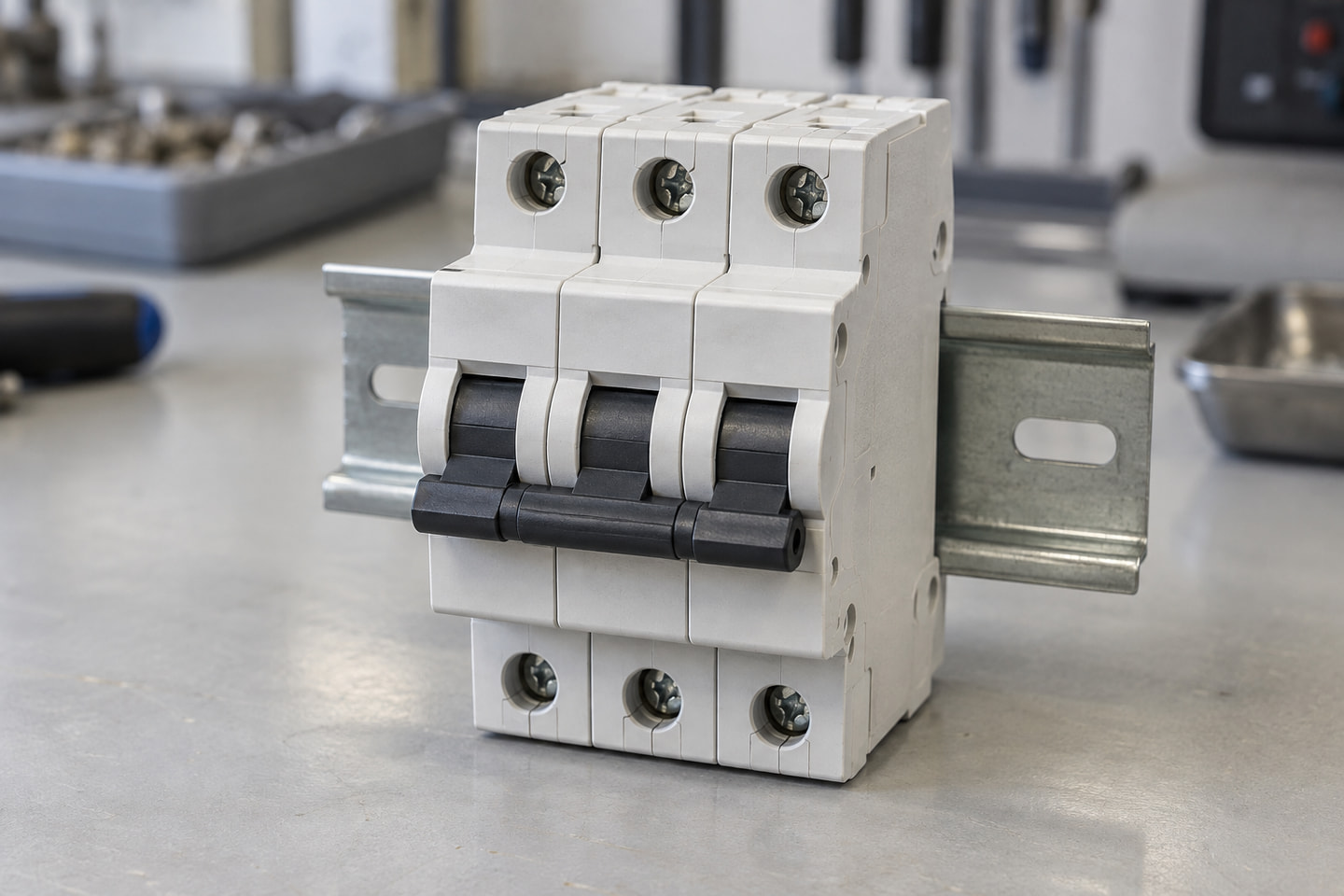
On a detailed three-phase drawing, a three-pole breaker can appear as three contact paths with a mechanical linkage between them. Each pole interrupts its own conductor. The linkage shows that the contacts belong to a coordinated mechanism.
The linkage is not an electrical connection between phases. A dashed line joining contact mechanisms must not be read as a wire connecting L1, L2, and L3. Electrical conductors and mechanical links have different meanings even when they cross the same area of the drawing.
Pole count tells you how many paths the device switches:
1P: one switched pole.
2P: two switched poles; the circuit context determines their use.
3P: three switched poles, commonly used for a three-phase circuit.
3P+N or 4P: additional neutral switching may be present, but the designation and device details determine which poles include overcurrent protection.
Do not equate the number of switched poles with the number of protected poles. A switched neutral, for example, does not automatically imply a separate overcurrent trip element in that pole.
Likewise, a visible handle linkage on real equipment is not enough to establish common automatic tripping. The device specification determines that function. On the drawing, use the complete breaker designation rather than inferring it from the linking line alone.
What Does an MCB Circuit Breaker Symbol Tell You About Tripping?
MCB means miniature circuit breaker. A detailed symbol may indicate thermal, magnetic, or combined thermal-magnetic operation. A simplified MCB symbol may show only the breaker function, leaving the trip characteristics to a label or equipment schedule.
In a thermal-magnetic MCB, the two mechanisms respond differently:
Thermal operation responds to sustained overcurrent. Heating deflects a bimetal element and operates the trip mechanism. Its response involves time, so a modest overload and a much larger overcurrent do not produce the same trip delay.
Magnetic operation responds rapidly to sufficiently high current. An electromagnetic mechanism releases the contacts when its operating threshold is reached.
A thermal or magnetic qualifier identifies the protection mechanism, not its complete performance curve. If the drawing shows a generic breaker symbol, you cannot derive the magnetic threshold or the overload trip time from its outline.
For example, an MCB labelled C16 commonly indicates a C characteristic and a rated current of 16 A. It does not mean the device trips instantly whenever current exceeds 16 A. The current level and duration must be interpreted using the appropriate time-current curve. Breaking capacity is another separate rating.
This also matters when a schematic is converted into a bill of materials. Two MCBs can share the same basic symbol while having different trip characteristics, voltage ratings, and interrupting capacities. The symbol establishes the circuit function; the selected part number establishes the actual device.
How Do You Read a Circuit Breaker Symbol on a Single Line Diagram?
A single-line diagram condenses a circuit into one path even when several conductors are involved. One breaker symbol can therefore represent a three-pole device. Counting the lines on the page will not reliably tell you the number of poles or wires.
Consider an illustrative feeder labelled in this order: supply bus, CB1, then load. Beside CB1, the drawing states 3P, 63 A.
Read that example in the following sequence:
Trace the connection. CB1 is between the supply bus and the downstream load, so opening it interrupts that feeder path.
Identify the device. CB1 is a reference designation connecting the graphic to the device schedule, not a model number by itself.
Read the poles. The 3P annotation identifies three poles even though the diagram uses one line.
Read the current annotation. In this example, 63 A is stated as the rated current. On other drawings, separate frame and trip ratings may appear, so their labels matter.
Locate the remaining protection information. Breaking capacity, adjustable trip settings, or an external protection relay may be specified elsewhere rather than encoded in the breaker graphic.
The example establishes circuit relationships; it does not establish whether that breaker is correctly selected for the installation. A complete protection assessment also needs system and device data that a simplified symbol cannot supply.
For a downstream PCB, another distinction becomes important: an external panel-mounted breaker may connect to the board through a terminal block or connector. The schematic breaker symbol does not mean the breaker itself mounts on the PCB. Board implementation must follow the selected components, their terminal assignments, and their physical dimensions.
EBest Circuit (Best Technology) provides PCB assembly services, including component sourcing and board assembly. For power or control board projects, this connects the selected BOM and PCB manufacturing data to the physical assembly; the circuit’s protection choices remain part of the electrical design.
What Do I and O Mean on a Circuit Breaker?
On equipment, I generally marks ON and O marks OFF. These are operating-position markings, not alternative schematic symbols for a circuit breaker. The circle-shaped O is easy to mistake for a zero, but its purpose here is to identify the OFF position.
Three indications should be kept separate:
I / ON: the closed operating position.
O / OFF: the open operating position.
TRIP: an automatic opening indication, where the device provides one. Some breakers use an intermediate handle position; others use a separate indicator.
An OFF indication and a trip indication can both accompany open contacts, but they describe different events. OFF alone does not identify which protective function operated, and not every breaker displays tripping in the same way.
The position of a contact on a printed schematic is different again. It represents the drawing’s defined condition, not the present condition of installed equipment. Neither a drawing nor a handle marking is a substitute for verifying absence of voltage before work.
FAQs About Circuit Breaker Symbol
What do CB and QF mean beside a breaker symbol?
They can be device reference designations. CB commonly identifies a circuit breaker, while QF appears in some designation systems and project conventions. A suffix such as CB1 or QF2 identifies a particular device. Use the drawing legend and equipment list rather than assuming every project uses the same letters.
Can the symbol alone tell me whether a breaker is suitable for AC or DC?
Usually not. A generic breaker graphic does not establish voltage suitability, polarity requirements, or the permitted pole arrangement. Those details come from the specific device ratings and connection instructions. An AC device must not be assumed suitable for DC because its schematic symbol looks the same.
Does a circuit breaker symbol show breaking capacity?
The basic graphic does not. Breaking capacity may be written beside it or listed in the equipment schedule. A current annotation such as 16 A or 63 A is not interchangeable with a fault-interruption rating expressed in kA.
Does the size of a CAD breaker symbol represent its physical dimensions?
No. A schematic symbol is scaled for readability and electrical connections. Physical dimensions belong to the product drawing, panel layout, or PCB footprint. Enlarging the symbol on a schematic does not change the size of the specified component.
What does push-to-reset mean on a circuit breaker?
It identifies a manual reset arrangement, often operated by a push button after the device trips. It does not, by itself, specify pole count, trip characteristic, or breaking capacity. Those remain separate device properties.
If you are turning a power or control board design containing a circuit breaker symbol into a manufactured assembly, EBest Circuit can discuss PCB fabrication, component sourcing, and PCBA requirements for your project. Send your available Gerber files, BOM, and assembly requirements to sales@bestpcbs.com to discuss the board build.
This website uses cookies to enhance your experience, remember your preferences, and help us understand how visitors use our site. You can accept all cookies, reject non-essential cookies, or manage your settings.
This website uses cookies to improve your experience while you navigate through the website. Out of these cookies, the cookies that are categorized as necessary are stored on your browser as they are essential for the working of basic functionalities of the website. We also use third-party cookies that help us analyze and understand how you use this website. These cookies will be stored in your browser only with your consent. You also have the option to opt-out of these cookies. But opting out of some of these cookies may have an effect on your browsing experience.
Necessary cookies are absolutely essential for the website to function properly. These cookies ensure basic functionalities and security features of the website, anonymously.
Cookie
Duration
Description
cookielawinfo-checkbox-analytics
11 months
This cookie is set by GDPR Cookie Consent plugin. The cookie is used to store the user consent for the cookies in the category "Analytics".
cookielawinfo-checkbox-functional
11 months
The cookie is set by GDPR cookie consent to record the user consent for the cookies in the category "Functional".
cookielawinfo-checkbox-necessary
11 months
This cookie is set by GDPR Cookie Consent plugin. The cookies is used to store the user consent for the cookies in the category "Necessary".
cookielawinfo-checkbox-others
11 months
This cookie is set by GDPR Cookie Consent plugin. The cookie is used to store the user consent for the cookies in the category "Other.
cookielawinfo-checkbox-performance
11 months
This cookie is set by GDPR Cookie Consent plugin. The cookie is used to store the user consent for the cookies in the category "Performance".
viewed_cookie_policy
11 months
The cookie is set by the GDPR Cookie Consent plugin and is used to store whether or not user has consented to the use of cookies. It does not store any personal data.
Functional cookies help to perform certain functionalities like sharing the content of the website on social media platforms, collect feedbacks, and other third-party features.
Performance cookies are used to understand and analyze the key performance indexes of the website which helps in delivering a better user experience for the visitors.
Analytical cookies are used to understand how visitors interact with the website. These cookies help provide information on metrics the number of visitors, bounce rate, traffic source, etc.
Advertisement cookies are used to provide visitors with relevant ads and marketing campaigns. These cookies track visitors across websites and collect information to provide customized ads.