A fuse symbol marks a protective device that opens a circuit when excessive current melts its fuse element. Reading it correctly involves more than recognizing the shape: the nearby reference number, rating, and circuit connections explain which fuse it is and what it protects.
At EBest Circuit, we support PCB fabrication, component sourcing, and SMT or through-hole assembly from your approved design. Matching the specified fuse to its PCB footprint and assembly documentation helps prevent component mismatches during production. For PCB and PCBA project support, contact sales@bestpcbs.com.
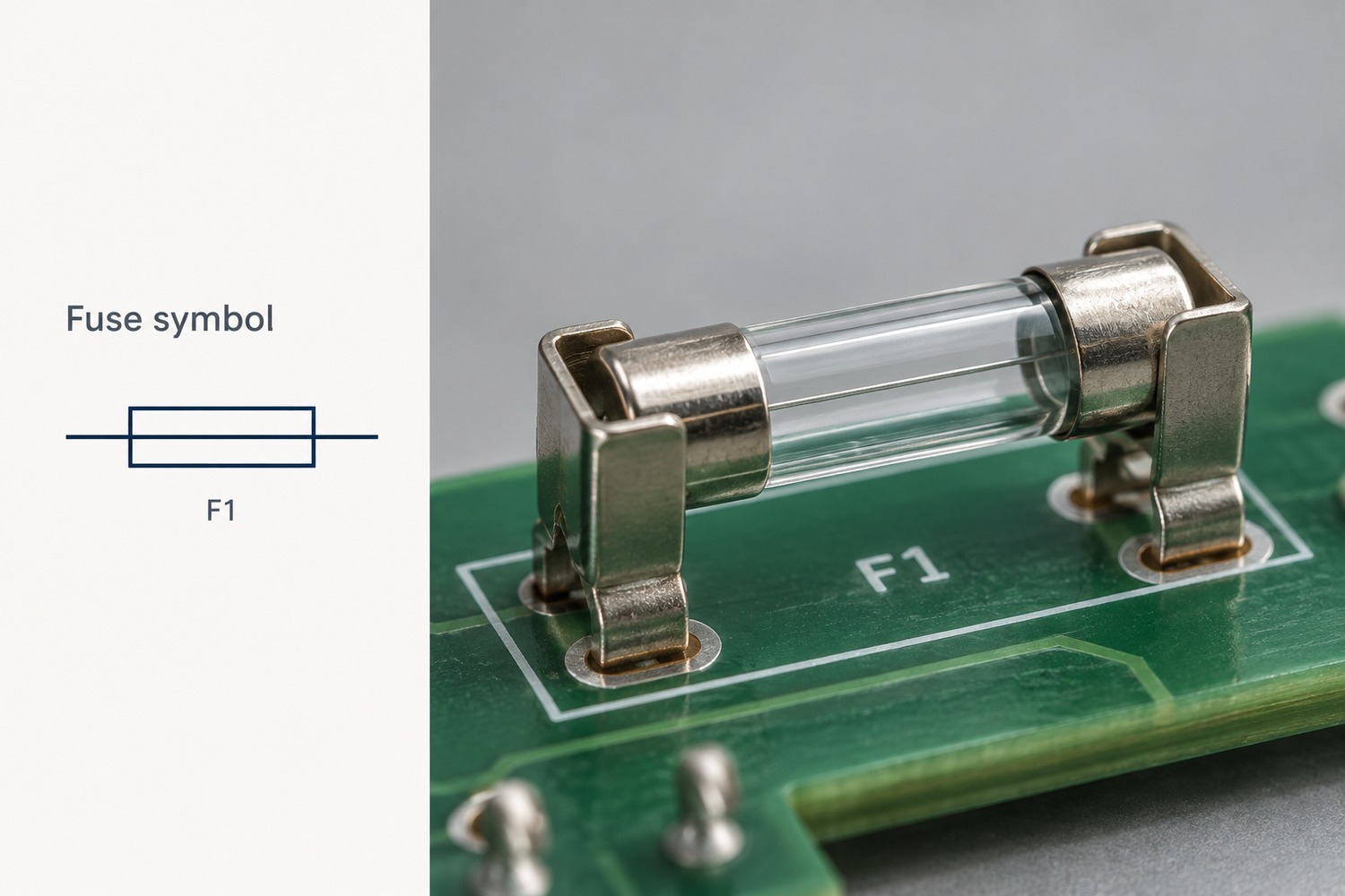
What Does a Fuse Symbol Look Like?
A common fuse symbol is a small rectangle with a straight line running through its center. Another familiar form uses a short curved or S-shaped element between the connecting wires. Both represent a fuse rather than its physical package.
The rectangle can resemble an IEC resistor symbol. The useful distinction is that the common rectangular fuse symbol has a line through the box, while the basic rectangular resistor symbol does not. Nearby identifiers also help: F1 commonly identifies a fuse; R1 identifies a resistor.
A curved fuse element can also resemble other symbols in a small drawing. Read the graphic together with its identifier and the drawing legend, rather than relying on the outline alone.
Why Do Fuse Symbols Look Different Across Diagrams?
Drawing standards, symbol libraries, and the amount of detail shown can all change a fuse’s appearance. IEC 60617 and IEEE/ANSI conventions are common references, but their implementations can overlap.
| Difference in the drawing | What it means |
|---|---|
| Rectangle with a center line or a curved element | Alternative representations encountered in different drawing conventions |
| Horizontal or vertical orientation | The symbol has been rotated to fit the circuit layout |
| Added striker or alarm-contact detail | The fuse assembly includes an indication or actuation feature |
A rectangle alone does not establish whether the entire drawing follows IEC or IEEE conventions. Both IEC and IEEE symbol libraries can contain the rectangular center-line form. Likewise, a different symbol shape does not automatically mean a different current rating or operating speed.
What Do the Markings Beside a Fuse Symbol Mean?
The reference designator identifies the component; the specification describes its electrical characteristics. For example, F1 means a particular fuse in the design, not a 1-amp fuse.
Consider a fuse identified as F1, with the specification T3.15AL250V. In the miniature-fuse marking convention used for this example:
| Marking | Meaning |
|---|---|
| F1 | Component reference, used to connect the schematic, BOM, and assembly drawing |
| T | Time-delay characteristic |
| 3.15A | Rated current of 3.15 amperes |
| L | Low breaking-capacity category |
| 250V | Rated voltage of 250 volts |
The rated current and breaking capacity describe different things. Rated current concerns normal current carrying; breaking capacity concerns safely interrupting a fault current. The letter L does not provide the complete numerical interrupting rating.
Similarly, 250V is not a voltage at which the fuse automatically blows. The applicable AC or DC rating comes from the device specification. This marking format is not universal for all fuse packages, particularly small surface-mount parts with manufacturer-specific codes.
How Are Fast-Blow and Slow-Blow Fuses Identified on Schematics?
The basic fuse symbol often stays the same; the accompanying value, note, or part number identifies the operating characteristic. In common miniature-fuse markings, F indicates fast-acting and T indicates time-delay.
- Fast-blow fuse: Intended to interrupt overcurrent without the intentional surge tolerance of a time-delay design. It still takes time to operate.
- Slow-blow fuse: Designed to withstand specified brief current surges, such as those associated with startup, while providing overcurrent protection.
For example, F2A and T2A both indicate a 2A current rating in this marking system, but their time-current behavior differs. They should not be treated as interchangeable solely because the current rating matches.
Also distinguish the F in F1, which identifies the component, from the F in F2A, which describes its speed. The manufacturer’s time-current curve defines the response more precisely than either the symbol or the word “fast.”
How Do You Read a Fuse Circuit Diagram?
Follow the current path through the fuse to the load and back to the supply. A fuse protecting a branch is connected in series with that branch, so the branch current passes through its element.
For a simple 12V DC circuit, the path is:
Supply +12V → F1 → Load → Supply return (0V)
This example shows three useful relationships:
- Normal operation: F1 conducts the load current and completes the supply path.
- Downstream fault: A short circuit can increase the current through F1. Whether and how quickly it opens depends on the available fault current and fuse characteristics.
- After F1 opens: The load loses this supply path. The section between the source and F1 can remain energized.
If another branch connects to the supply before F1, that branch is outside F1’s protection path. This is why the connection points matter more than how close the fuse appears to a component on the page.
How Does a Fuse Symbol Relate to the Actual Component?
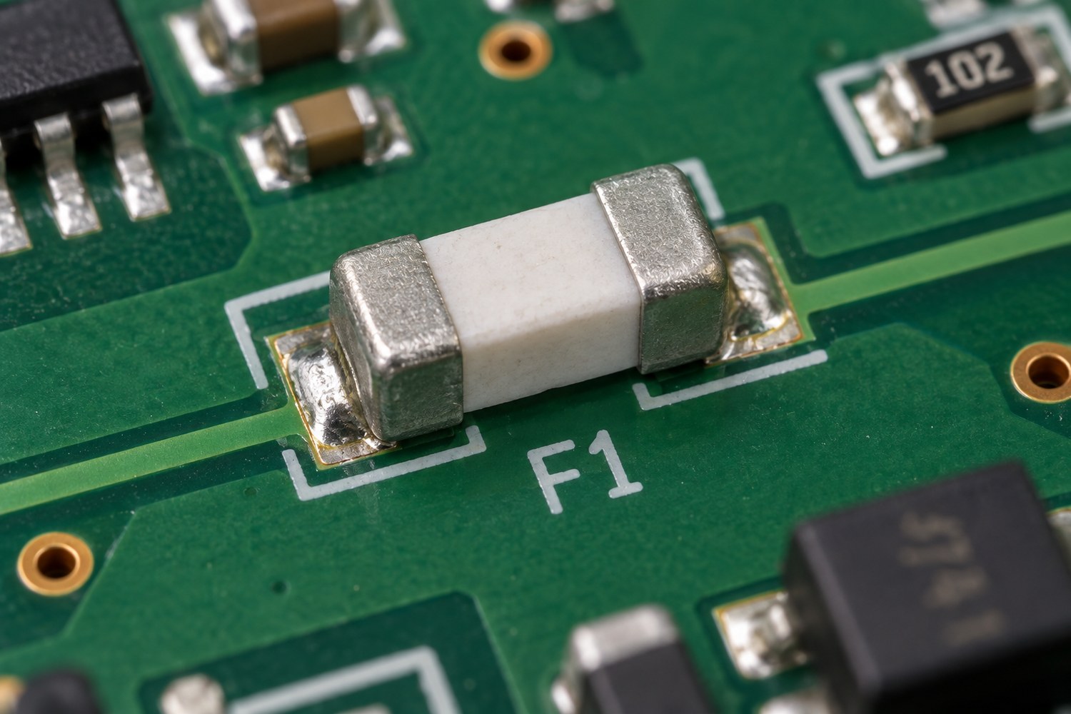
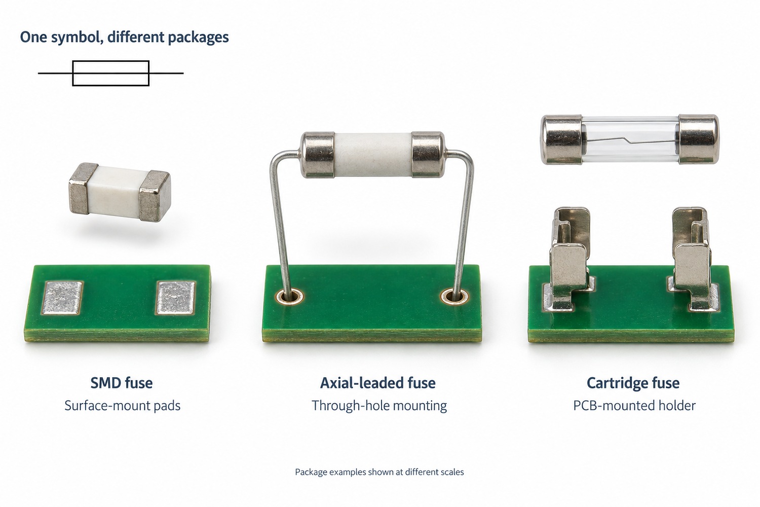
One basic schematic symbol can represent several physical fuse packages. It may correspond to a small SMD chip, a leaded fuse, or a cartridge fitted into a holder.
| Design element | What it describes |
|---|---|
| Schematic symbol | Electrical function and circuit connections |
| BOM part number | The specified device and its characteristics |
| PCB footprint | Pads or holes needed for the mounted component |
| Assembly reference | Where that component belongs on the board |
For a cartridge fuse, the PCB may carry the holder, while the replaceable fuse sits inside it. The board footprint must therefore match the holder’s terminals and dimensions.
Changing to another fuse with the same current rating may still require a different footprint, holder, or assembly process. The symbol alone does not establish mechanical compatibility.
Does a Fuse Symbol Show Whether the Fuse Has Blown?
An ordinary schematic fuse symbol does not report the fuse’s present condition. It identifies the device and its connection in the intended circuit.
A fault-analysis drawing may explicitly show an open fuse, while another drawing may include a fuse-operated alarm contact. Those details need to be interpreted through the drawing notes or legend; they are not live status indications by themselves.
The physical fuse’s condition requires inspection or measurement. For a conventional fuse, continuity testing is performed with power disconnected and stored energy discharged. Parallel circuit paths can produce a misleading reading, so isolation may be necessary. A printed symbol or an intact-looking fuse body is not sufficient evidence that the fuse is working.
FAQs About Fuse Symbols
Do AC and DC fuses use different symbols?
The basic symbol can be the same. AC and DC suitability is established by the specified fuse’s ratings, not by its symbol alone. An AC voltage rating does not automatically establish an equivalent DC rating.
How is a thermal fuse different from an ordinary fuse?
A thermal fuse opens at a specified temperature, while an ordinary overcurrent fuse responds to heating caused by current through its element. Thermal-fuse drawings may include a temperature notation or a distinct library symbol. Its electrical ratings still matter.
Is a resettable PTC the same as a fuse?
No. A resettable PTC increases its resistance when it trips, limiting current rather than creating the permanent open circuit of a melted fuse element. It can recover after the fault is removed and it cools, subject to the device’s operating conditions.
Does an SMD fuse need a special schematic symbol?
Usually, the basic fuse symbol is sufficient. The BOM and footprint distinguish an SMD package from a leaded or cartridge version. A tiny code printed on the component may be a manufacturer-specific rating code.
Are car fuse-box icons the same as schematic fuse symbols?
Not necessarily. A fuse-box cover may use icons to identify the protected function, such as lighting or a power outlet. A schematic fuse symbol identifies the protective device within the electrical circuit. The vehicle’s legend explains its particular icons.
For a PCB assembly project, the fuse symbol, specified part, and physical footprint should describe the same intended device. EBest Circuit can support fabrication, sourcing, and assembly from your approved files. Discuss your next build with us at sales@bestpcbs.com.