PCB manufacturing PCB manufacturing
Home > Blog

aluminum pcb design

Long Aluminum PCB: LED Lighting, Flatness and Manufacturing
Friday, October 9th, 2026

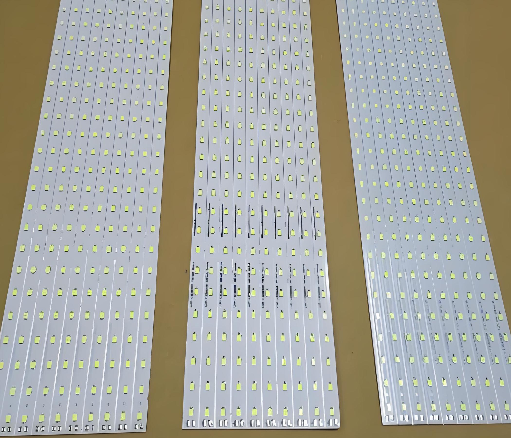
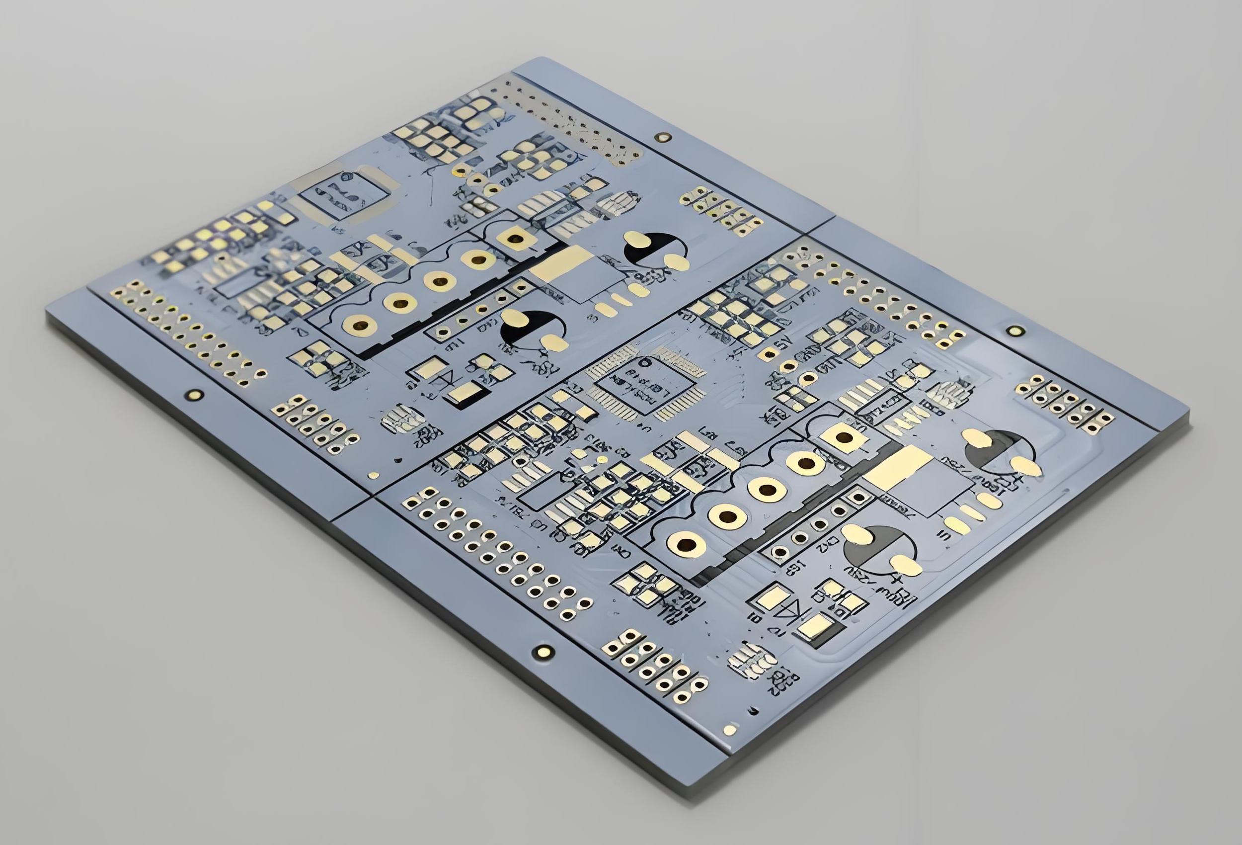
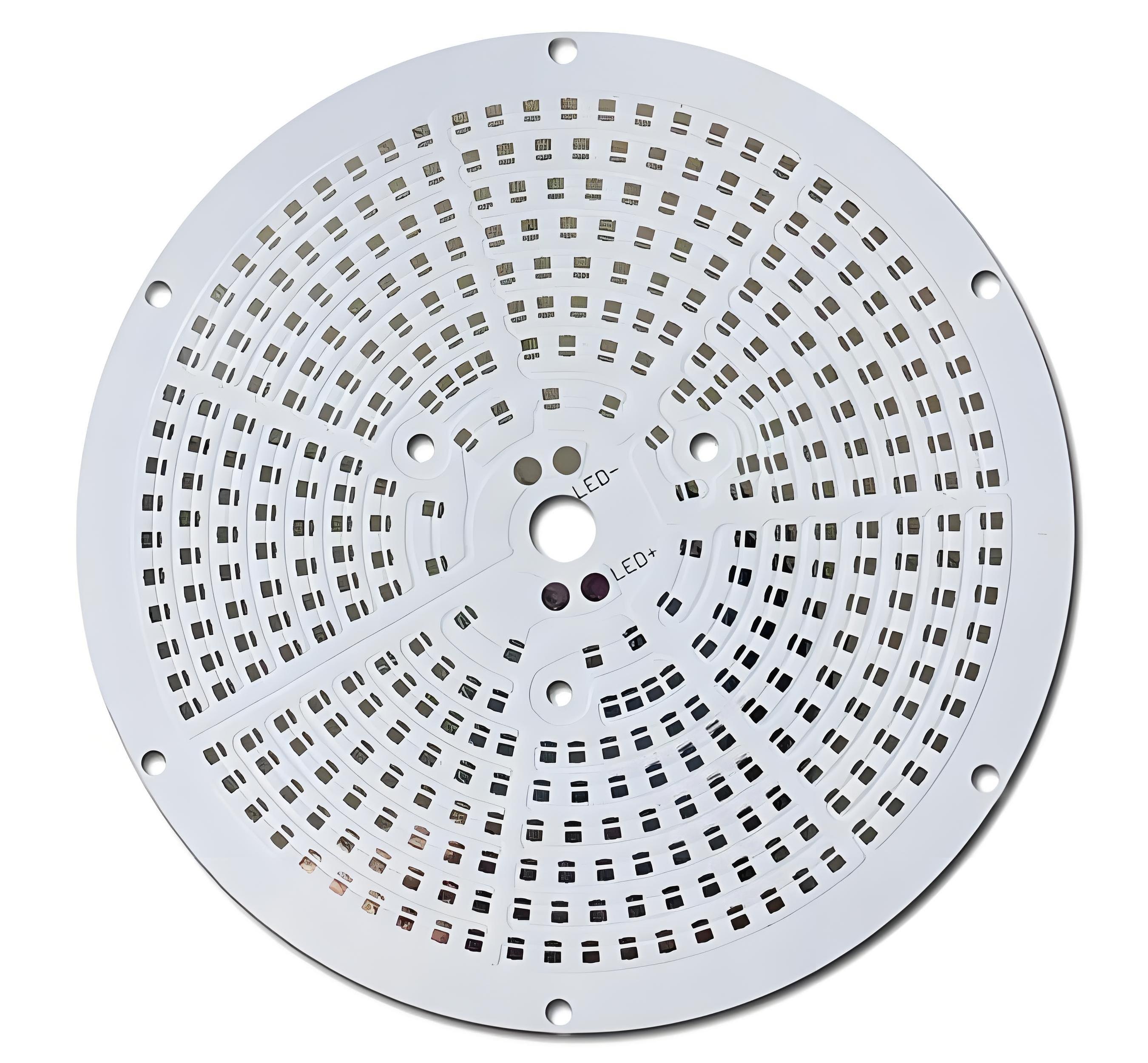
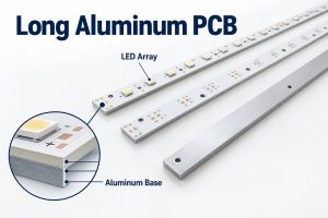
A long aluminum PCB is an elongated metal-core circuit board that carries an LED array and transfers heat toward the light fixture’s heatsink. Its copper circuit is separated from the aluminum base by a thermally conductive electrical insulation layer. For a 1.2-meter design, the main questions are usable manufacturing length, flatness after processing, and compatibility with the assembly line—not length alone.

At EBest Circuit, we support aluminum PCB fabrication, component sourcing and PCB assembly. Send your board drawing and thermal requirements for a DFM review before fixing the material or production layout.
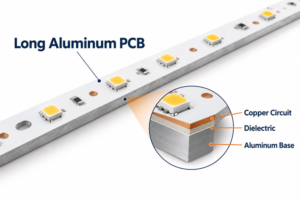
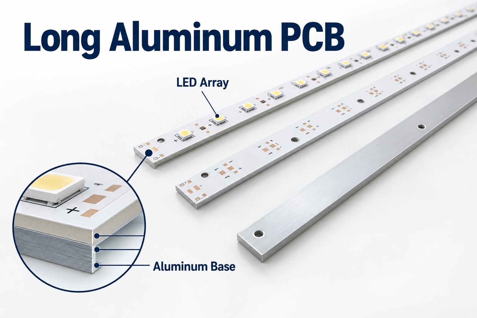
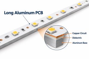
Long aluminum LED PCB with a magnified copper, dielectric and aluminum base cross section

Key Takeaways

  • A long aluminum PCB combines electrical routing with a metal heat-spreading base for linear LED lighting.
  • Our MCPCB capability table lists 480 × 1180 mm regular aluminum large-sheet dimensions and 1600 × 480 mm special single-sided processing. Finished-board and assembly dimensions require separate confirmation.
  • A 1.2-meter strip needs an agreed flatness limit, measurement condition and heatsink mounting arrangement.
  • Dielectric options include 1, 2 and 3 W/m·K grades. Thickness and thermal resistance matter alongside conductivity.
  • Long-board process planning must address support, profiling, handling and soldering—not just the laminate size.
  • Marine lighting requires coordinated moisture, corrosion and enclosure design. A bare PCB does not establish a luminaire’s environmental rating.
  • Quote files should define the mechanical drawing, material, quantities and acceptance tests, with BOM and placement data for PCBA.

What Is a Long Aluminum PCB?

A long aluminum PCB is a rigid aluminum-based circuit board whose elongated shape suits a linear product, such as an LED light bar. “Long” describes the geometry; it is not a separate electrical technology or a standardized length class.

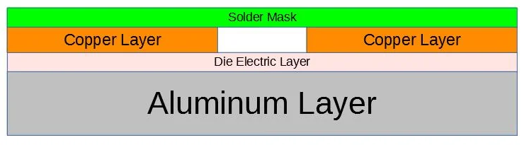
A typical single-sided aluminum PCB stackup contains these layers:

Layer Function
Copper circuit Connects LEDs, resistors and power connections.
Thermally conductive dielectric Electrically isolates the circuit from the metal while conducting heat.
Aluminum base Supports the board and spreads heat toward the mounting surface.

Solder mask covers the circuit except at exposed pads. Aluminum boards belong to the metal core PCB family; the metal base is not automatically an electrical ground connection.

Why Are Long Aluminum PCBs Used in LED Lighting?

Long aluminum PCBs fit continuous LED rows while providing a heat-transfer path to a linear heatsink or housing. A single board can also reduce the number of connectors between shorter LED modules.

They suit architectural light bars, linear fixtures and selected marine lighting assemblies. The board supports LED placement along the optical path, but uniform brightness still depends on the driver, LED spacing, bin selection and optical design.

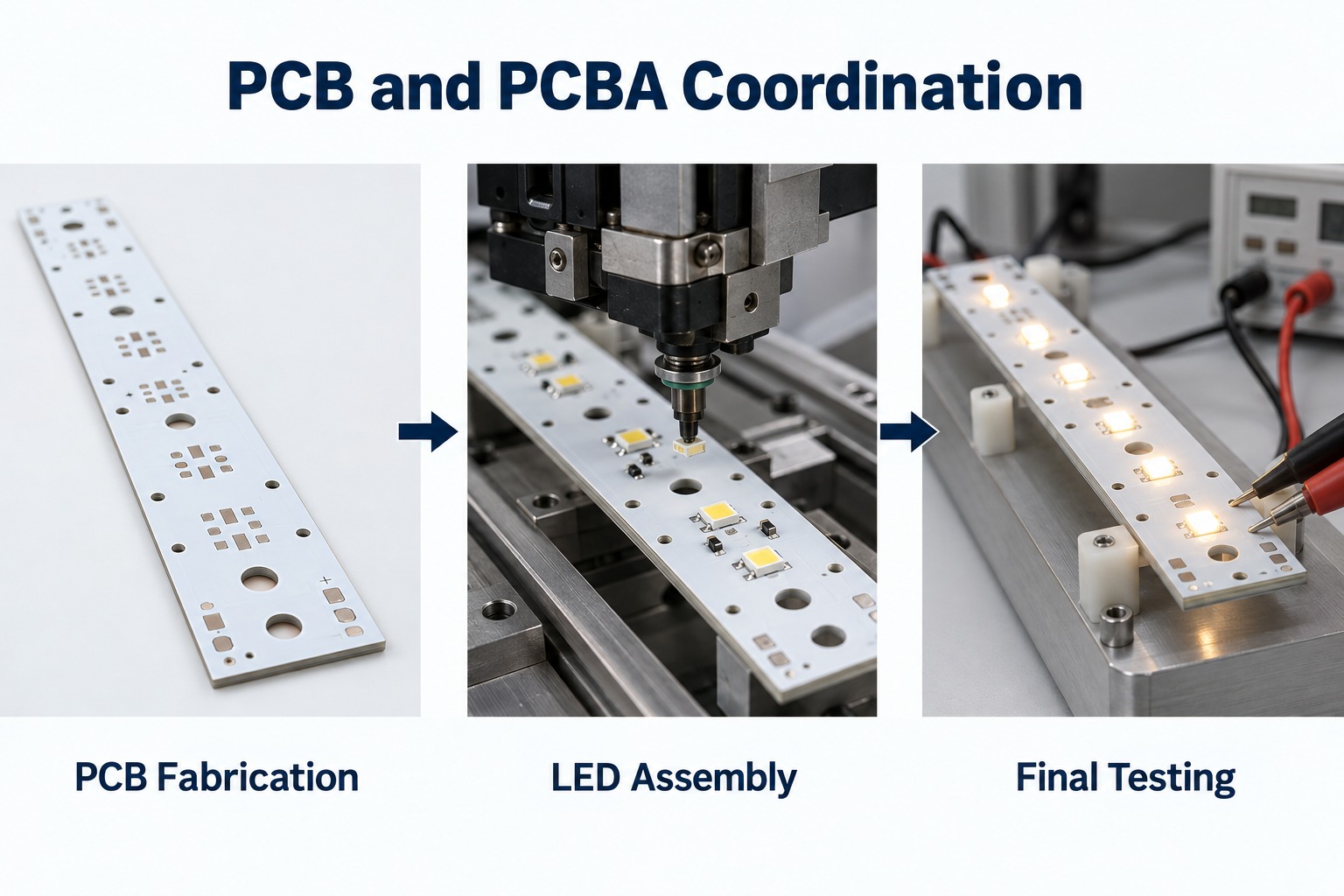
We can bring the aluminum light board and a separate FR-4 driver or control board into the same PCB/PCBA project. This lets the mechanical interfaces, connectors and test requirements be reviewed together. It does not require forcing a complex driver circuit onto the LED board.

How Long Can an Aluminum PCB Be?

Our MCPCB capability table lists 1600 × 480 mm for special single-sided aluminum processing, alongside a regular aluminum large-sheet size of 480 × 1180 mm. These figures describe different processing categories, not a blanket maximum for every finished board.

A 1200 mm finished strip exceeds the listed regular sheet length. It therefore needs a special-process review, including tooling space and the usable area remaining after manufacturing margins.

Capability item Listed range or condition
Regular aluminum large sheet 480 × 1180 mm
Special single-sided aluminum processing 1600 × 480 mm; project review required
Regular processing thickness 0.8–3.0 mm
Thicker material 4.0 and 5.0 mm by material order and confirmation
1 oz copper line/space 0.20/0.20 mm regular; 0.15/0.15 mm special

These parameters are not guaranteed in every combination. Before releasing a long-board order, confirm three dimensions separately: the finished PCB, the fabrication panel, and the assembly carrier or panel. The printer, placement machine, reflow transport and inspection equipment each need to accommodate the approved format.

Why Is Flatness Difficult on a 1.2-Meter Aluminum PCB?

A 1.2-meter aluminum PCB makes small curvature more visible because the unsupported span is long. Its copper, dielectric and aluminum layers also respond differently to heating and cooling.

  • Material and copper distribution: an asymmetric construction can develop uneven stress through processing.
  • Thermal history: curing and soldering cycles can change the board’s free-state shape.
  • Profiling and support: a narrow strip may move when it is separated from a larger panel.
  • Handling and mounting: unsupported lifting or forcing the strip against uneven screw positions can introduce deformation.
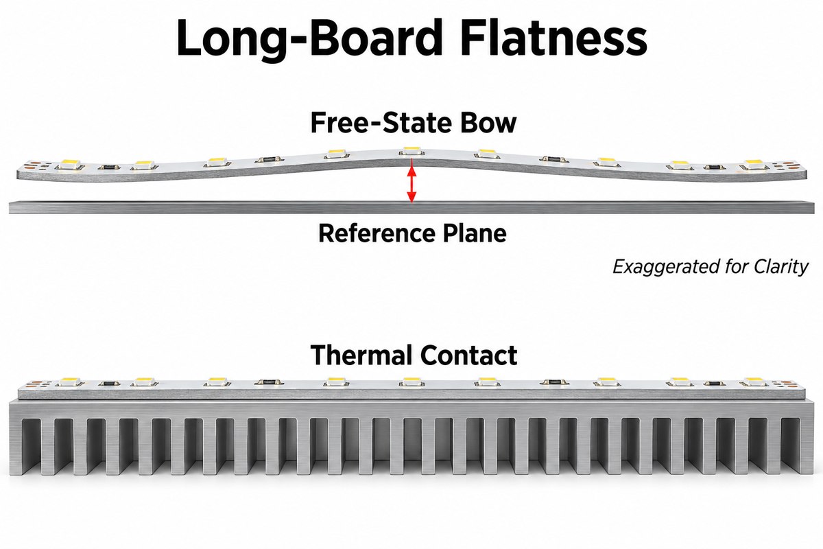
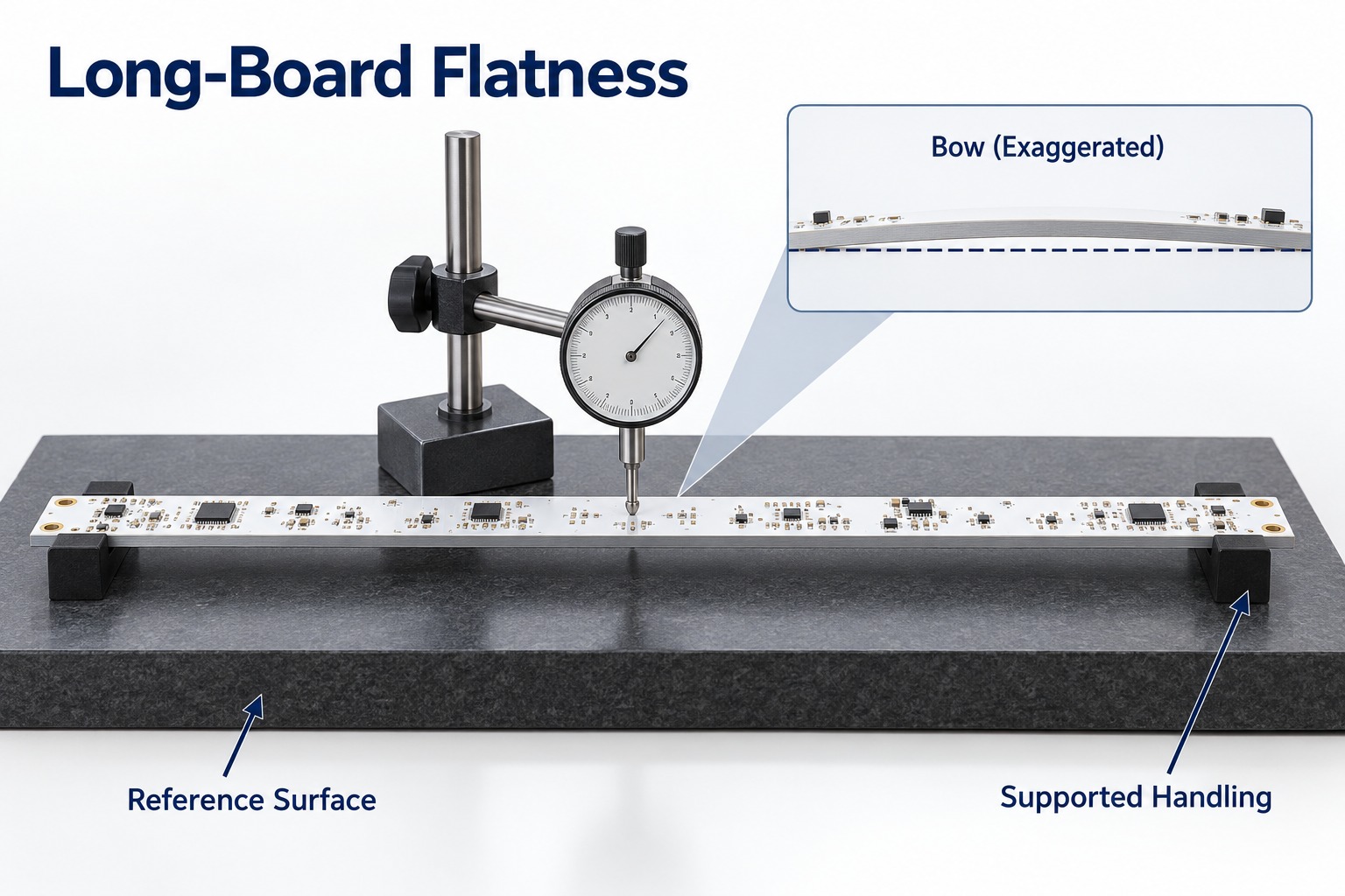
Exaggerated free-state bow in a long LED board compared with flat contact on a heatsink

Specify flatness in the drawing with a measurement method. State whether the board is free or restrained, where it is supported, and whether inspection occurs before or after assembly. For illustration only, 0.5% of 1200 mm is 6 mm: a percentage that appears small can allow a large gap. This is not a recommended acceptance limit or an IPC test calculation.

How Do We Maintain Yield on Long, Narrow Aluminum PCBs?

Our starting point is a DFM review that connects the long-board layout with a practical fabrication and inspection plan. The detailed support method and process settings must be qualified for the selected design.

For long, narrow boards, the production review should resolve:

  1. Material and panel layout: confirm the selected laminate is available in the required usable size. Include tooling and handling margins.
  2. Support during processing: establish how the strip is held during machining, inspection and any assembly operation.
  3. Profile and hole quality: check edge clearances, mounting-hole positions and burr control against the drawing.
  4. First-article release: verify dimensions, flatness and electrical results before approving the production arrangement.
  5. Handling and packing: support the board along its length and prevent bending loads during transport.

For assembly, add stencil support and a soldering profile validated on the actual aluminum construction. Aluminum PCB design decisions should be reviewed before tooling is ordered; correcting a support or mounting problem after production starts adds rework. A meaningful yield figure must refer to a defined product and inspection plan, not an unrelated short-board run.

How Should You Choose Dielectric Thermal Conductivity for an LED Aluminum PCB?

Start by comparing the available 1, 2 and 3 W/m·K dielectric grades against the LED temperature budget, then check dielectric thickness and electrical insulation requirements. Our material table lists higher-conductivity 3–8 W/m·K options as requiring a material inquiry.

Aluminum PCB thermal conductivity is often quoted as the dielectric value—not the conductivity of the aluminum base or the complete board. Our listed regular dielectric thickness for specified material families is 100–110 ”m; 150 and 200 ”m options require confirmation.

For an ideal uniform layer, thermal resistance is proportional to thickness divided by conductivity and heat-transfer area: R = t/(kA). At equal area, doubling conductivity halves that layer’s calculated resistance; doubling thickness cancels that benefit. The complete LED-to-ambient path also includes the package, solder connection, mounting interface and heatsink.
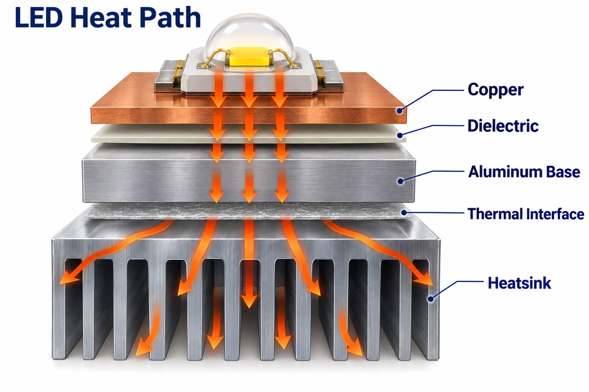
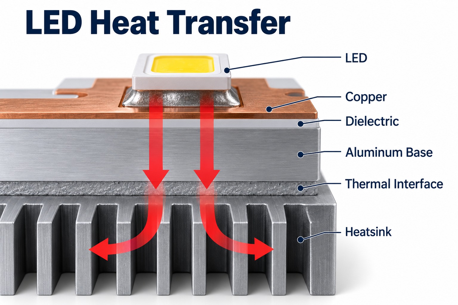
Illustrated heat path from an LED through the dielectric and aluminum base to a heatsink

Request the exact laminate grade and its test method rather than comparing unlabeled conductivity numbers. Confirm insulation performance separately, and validate LED temperature in the intended housing at the specified operating current and ambient temperature. Higher conductivity alone does not establish an acceptable junction temperature.

What Should Be Checked for Marine LED Lighting PCBs?

Marine LED lighting PCBs need checks for moisture exposure, corrosion paths and insulation, together with the luminaire’s sealing and heat-transfer design. Interior cabin lighting and an exposed exterior fixture do not face identical conditions.

  • Water entry and condensation: define the expected exposure and how the enclosure, seals and cable entries manage it.
  • Exposed metal: review board edges, mounting holes and dissimilar-metal contacts for the intended environment.
  • Coating or potting: specify coverage and keep-outs for LEDs, connectors and heat-transfer surfaces; check material compatibility.
  • Mechanical installation: assess mounting stress, vibration and connector strain relief.
  • Electrical protection: define operating voltage, insulation requirements and the driver’s protection needs.
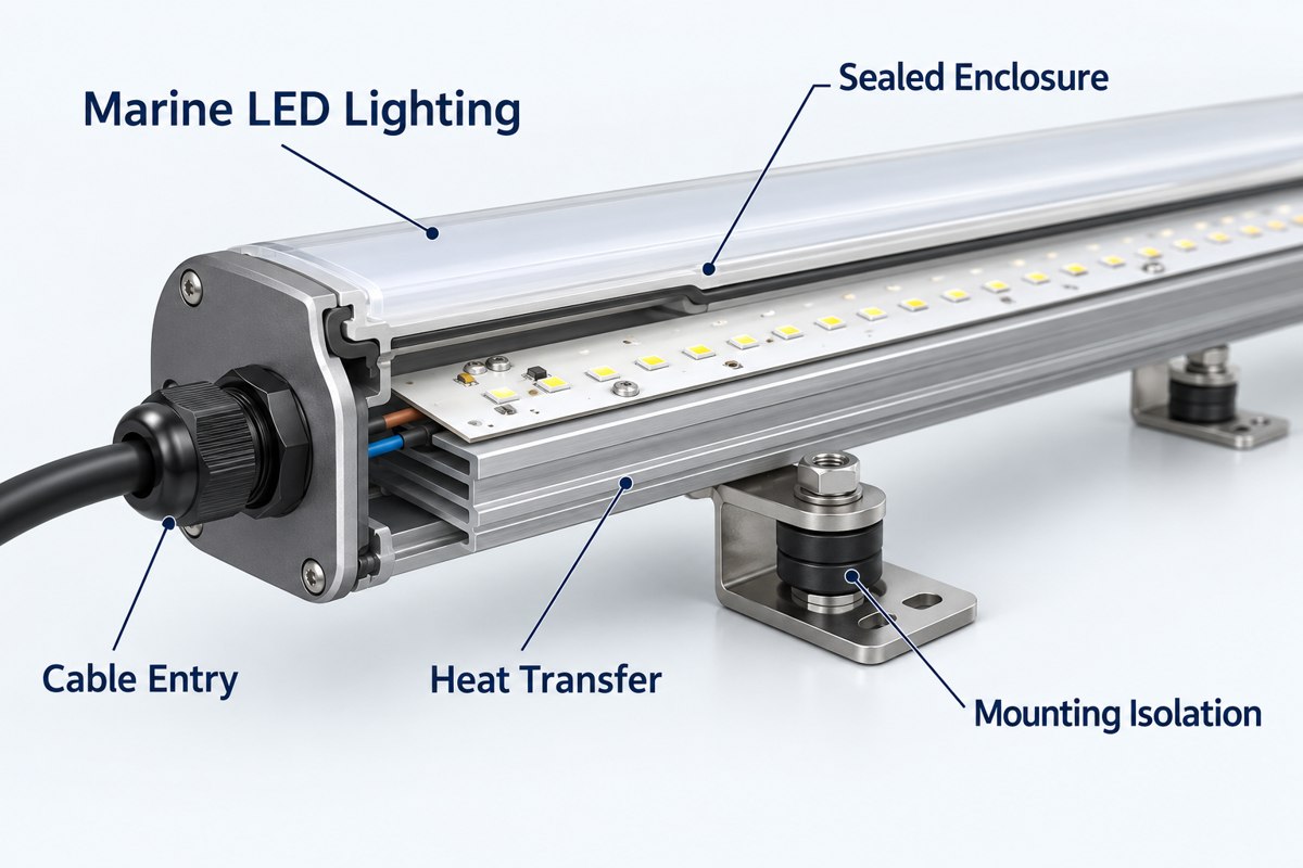
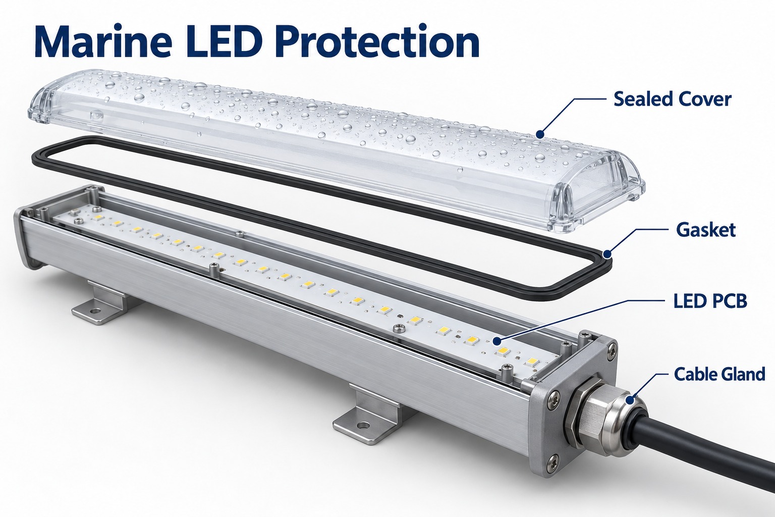
Conceptual cutaway of a marine linear LED light showing enclosure, cable entry, mounting isolation and heat transfer

The qualification plan should identify tests for the PCB, PCBA and complete fixture separately. A coating on the board does not by itself establish an IP rating, and a company quality-system certificate is not marine product approval.

What Tests Are Important for Long Aluminum PCBs?

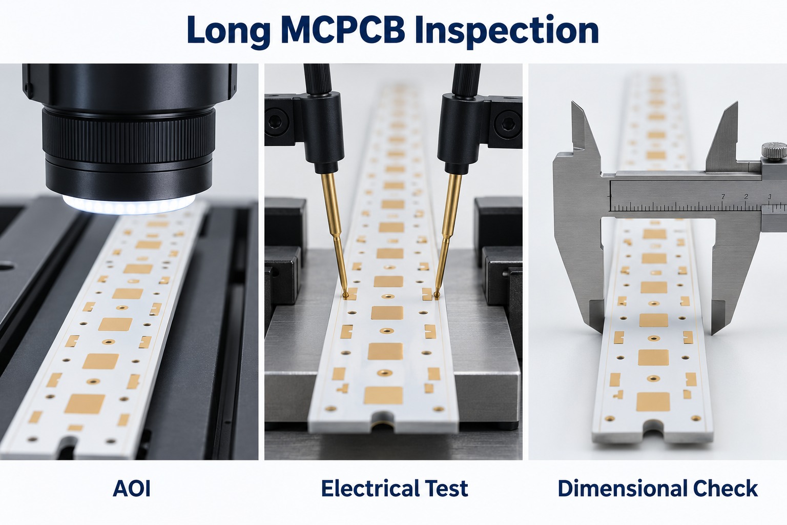
Long aluminum PCBs need dimensional and flatness checks plus electrical continuity and short-circuit testing. Assembled LED boards also need solder-joint inspection and the functional checks defined for the lighting circuit.

Stage Check What it verifies
Bare PCB Dimensions, holes and flatness Fit against the released mechanical drawing
Bare PCB Open/short electrical test Circuit connectivity against approved data
PCB or PCBA, as specified Insulation resistance or dielectric withstand Insulation under the agreed test conditions
PCBA Paste and solder inspection Deposit quality, placement and inspectable solder joints
PCBA Powered functional test LED polarity, string operation and specified electrical behavior
Qualification build Thermal and environmental validation Performance in the defined installation and exposure
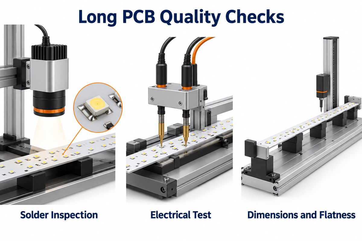
Conceptual optical inspection, electrical probing and dimensional checking of long LED PCBs

Our listed inspection resources include AOI, electrical testing, dimensional measurement, SPI, X-ray and functional testing. The selected methods, equipment size coverage and acceptance criteria must match the actual long-board project. X-ray is relevant where a joint cannot be assessed adequately by optical inspection; it is not a substitute for a functional test.

Agree the test voltage, duration, limits and sampling plan before ordering. Separate qualification tests from routine production tests so neither cost nor acceptance depends on an unstated assumption.

What Should Buyers Ask an Aluminum PCB Manufacturer?

Ask an aluminum PCB manufacturer to confirm the usable finished-board size and the corresponding assembly route in writing. A maximum sheet dimension alone does not answer whether your long LED strip can be built and tested.

  • Which laminate grade, dielectric thickness and copper thickness are included in the quote?
  • How will flatness be measured, and which limit applies after soldering?
  • Which fabrication and assembly operations are in-house, and which need another facility or a special process?
  • What first-article records and production test results will be supplied?
  • What are the prototype and repeat-order quantities, lead times and tooling charges?
  • How are approved material substitutions and LED bin requirements controlled?
  • How will long strips be packed, and what purchasing commitments apply to forecast or stocked material?

Compare quotations using the same drawing revision and test scope. A lower bare-board price can conceal different material, inspection or packaging assumptions.

What Files Should You Send for an Aluminum PCB Quote?

Send fabrication data and a dimensioned drawing first; add the BOM, placement file and assembly drawing when you need a populated LED board.

  • PCB data: Gerber or ODB++ files, drill data, outline and revision.
  • Mechanical requirements: length, width, thickness, mounting holes, flatness limit and measurement condition.
  • Material specification: laminate grade or required dielectric properties, copper thickness, solder mask and surface finish.
  • Assembly data: manufacturer part numbers, approved alternatives, LED bin requirements, placement coordinates and polarity notes.
  • Validation scope: electrical limits, functional test procedure and any thermal or environmental qualification requirements.
  • Commercial information: prototype quantity, production lot sizes, forecast and required delivery schedule.

A heatsink or enclosure drawing is useful when board contact and mounting affect acceptance. Our PCB design guides provide additional background, but the released project drawing should define the actual requirements.

FAQ About Long Aluminum PCBs

Can a long aluminum PCB replace a flexible LED strip? Only where the installation accepts a rigid board. A conventional aluminum PCB cannot follow curves like a flexible strip, so the mechanical layout and mounting method may need to change.

Is white solder mask an electrical insulation layer? No. In the basic metal-core stackup, the specified dielectric isolates the copper circuit from the aluminum base. White solder mask covers the circuit surface and must not be treated as a replacement for that insulation.

Can LEDs and their driver use the same aluminum board? They can share a board if routing, insulation, thermal conditions and assembly access permit. A separate FR-4 driver board may be more practical when the driver requires more complex routing.

Does increasing aluminum thickness always solve overheating? No. It can change heat spreading and stiffness, but it does not remove resistance in the dielectric or a poor board-to-heatsink interface. Check the complete thermal path before changing thickness.

Can a long board be divided into shorter modules? Yes, if the optical and electrical design allows it. The trade-off is easier handling against additional interconnections, mechanical joints and possible gaps in the light pattern.

Why Choose EBest Circuit for Long Aluminum PCB and PCBA Projects?

We connect aluminum PCB fabrication with component sourcing and PCB assembly, so the light board, components and inspection requirements can be reviewed as one build. Our MCPCB capability table distinguishes regular materials and processing from special long-board requirements instead of treating every design as a standard panel.

For a new long-strip project, send the board drawing, Gerber files, material requirements and quantities to sales@bestpcbs.com. Include the BOM and test requirements if assembly is needed. We can then identify the engineering questions that must be resolved before prototype and production quotations are finalized.
You may also like

Long Aluminum PCB for LED Lighting: Manufacturing Guide
Thursday, October 8th, 2026

A long aluminum PCB is commonly used in linear LED lighting, architectural luminaires, commercial fixtures, transit lighting, and marine lighting. Its aluminum base helps support the board mechanically while transferring heat away from the LED area.

When board length approaches 1,000–1,200 mm, manufacturing becomes more demanding. Flatness, registration, thermal stress, testing, and handling all need tighter control, especially for long and narrow LED boards.

At EBest Circuit, we review aluminum PCB fabrication and LED assembly requirements together, including board dimensions, materials, handling, and inspection before production.

Long aluminum LED PCBs showing LED array and aluminum base

Key Takeaways

  • Long aluminum PCBs are widely used in linear LED lighting because they provide mechanical support and a direct path for heat spreading.
  • Once board length approaches 1,000–1,200 mm, flatness, registration, handling, and dimensional consistency become much harder to control.
  • Manufacturing difficulty depends on length, width, thickness, copper distribution, and panel design together, not board length alone.
  • Thermal conductivity is only one part of LED thermal design. Dielectric thickness, thermal resistance, copper weight, and heatsink contact also matter.
  • Long MCPCBs need tighter control of AOI, electrical testing, dimensional inspection, flatness, and packaging.
  • One-stop PCB and PCBA manufacturing can simplify traceability, LED bin control, DFM/DFA, SMT process matching, and volume ramp-up.

What Is a Long Aluminum PCB?

A long aluminum PCB is an elongated metal-core PCB used when LEDs or other components need to be arranged across a long, narrow board. It typically consists of a copper circuit layer, a thermally conductive dielectric, and an aluminum base. This aluminum PCB stackup separates the circuit from the metal base with an insulating dielectric.

A typical structure includes:

  • Copper circuit layer
  • Thermal dielectric
  • Aluminum base
  • Solder mask
  • Surface finish on exposed pads

The aluminum base provides mechanical support and helps transfer heat away from the circuit area. In LED lighting, long aluminum PCBs are commonly used for linear fixtures, LED strips, architectural lighting, and other applications that need both heat dissipation and a long board format.

Why Are Long Aluminum PCBs Used in LED Lighting?

Long aluminum PCBs are used in LED lighting because they support long LED arrays while creating a shorter thermal path from the LEDs to the fixture or heatsink.

LED heat path through copper dielectric aluminum base thermal interface and heatsink

Typical applications include:

  • Linear architectural lighting
  • Commercial LED luminaires
  • Cove lighting
  • Transit lighting
  • Marine lighting
  • Industrial linear fixtures
  • LED signage
  • Long LED strips

The typical thermal path is:

LED → solder joint → copper layer → dielectric → aluminum base → fixture or heatsink

This structure helps spread heat across the board instead of concentrating it around individual LEDs.

Many lighting products also use FR4 boards for driver, control, communication, or protection circuits. A complete lighting assembly may therefore include:

How Long Can an Aluminum PCB Be Manufactured?

The maximum aluminum PCB length depends on whether every production process can handle the required board size.

The main equipment limits are:

  • Imaging and exposure
  • Etching
  • Solder mask processing
  • Surface finish
  • Routing or V-scoring
  • AOI
  • Electrical testing
  • Handling and packaging
Board Length Main Manufacturing Concern
Below 600 mm Standard MCPCB processing in many factories
600–900 mm Equipment size and handling
900–1200 mm Flatness, registration, and dimensional consistency
Above 1200 mm Detailed equipment and process review required

For boards around 1,000–1,200 mm, the manufacturer should review the actual design before confirming production capability.

Important data includes:

  • Length and width
  • Aluminum thickness
  • Copper weight
  • Dielectric system
  • Surface finish
  • Panel layout
  • Dimensional tolerance

A factory being able to process a 1,200 mm sheet does not automatically mean every 1,200 mm PCB design is equally easy to manufacture.

Why Is Flatness Difficult on a 1.2-Meter Aluminum PCB?

Flatness is harder to control on a 1.2-meter aluminum PCB because small material and process stresses become more visible over a long distance.

Long aluminum PCB flatness inspection and exaggerated bow

The main factors include:

  • Long and narrow board shape
  • Aluminum thickness
  • Uneven copper distribution
  • Dielectric construction
  • Thermal processing
  • Routing stress
  • Storage method
  • Packaging pressure

Thin and narrow boards are usually more sensitive because they have less mechanical stiffness.

Copper balance also affects flatness. Large differences in copper coverage can create uneven stress during heating and cooling.

That is why long-board manufacturability should be evaluated using:

Length × Width × Thickness

For example:

  • 1200 × 20 × 1.0 mm
  • 1200 × 100 × 2.0 mm

Both are 1.2 meters long, but the first requires much more careful handling and flatness control.

How Do We Control Yield on Long, Narrow MCPCBs?

We control yield on long, narrow MCPCBs by reducing process variation from material preparation through final inspection.

Material and panel planning

Before production, we review:

  • Board dimensions
  • Aluminum thickness
  • Copper distribution
  • Trace layout
  • Panel method
  • Routing direction

A stable panel layout makes long boards easier to process and handle.

Registration control

Long boards are more sensitive to accumulated positional error. We therefore control:

  • Imaging alignment
  • Drilling accuracy
  • Solder mask registration
  • Hole-to-profile position
  • Final dimensions

Etching consistency

Trace width and copper geometry must remain stable across the full board length. This is especially important for long LED arrays with repeated circuit patterns.

Thermal process control

Heating and cooling conditions are controlled to reduce unnecessary internal stress and board deformation.

Mechanical handling

Long narrow boards require adequate support during:

  • Transfer
  • Inspection
  • Stacking
  • Storage
  • Packing

This helps prevent bending, scratching, and edge damage.

Inspection

Depending on the project, inspection can include:

  • Dimensional checks
  • AOI
  • Solder mask inspection
  • Flatness measurement
  • Electrical testing
  • Final visual inspection

For long MCPCBs, yield depends heavily on stable processing before final inspection rather than relying on sorting at the end.

What Thermal Conductivity Should an LED Aluminum PCB Use?

The correct thermal conductivity depends on the complete thermal design, not just the W/m·K rating of the dielectric. Specify aluminum PCB thermal conductivity together with dielectric thickness and insulation requirements.

Key parameters include:

  • Thermal conductivity
  • Dielectric thickness
  • Thermal resistance
  • Breakdown voltage
  • Copper thickness
  • LED power density
  • LED spacing
  • Heatsink contact
  • Operating temperature

A higher thermal conductivity value is useful only when the dielectric thickness and complete thermal path also support efficient heat transfer.

Application Main Thermal Concern
Low-power LED lighting Cost and basic heat spreading
Linear LED lighting Continuous heat transfer
High-density LED boards Local hotspot control
High-power LED modules Low thermal resistance
Marine LED lighting Thermal and environmental stability

For most LED projects, the better selection question is:

Which dielectric system provides the required thermal resistance, insulation, reliability, and cost?

This gives a more accurate result than selecting a board only because it is rated at 2 W/m·K or 3 W/m·K.

What Should Be Checked for Marine LED Lighting PCBs?

Marine LED lighting PCBs need both thermal control and environmental protection.

Marine LED luminaire cover gasket board and cable gland

The main points to check are:

  • Moisture resistance
  • Corrosion resistance
  • Surface finish
  • Conformal coating
  • Connector protection
  • Solder joint protection
  • Enclosure sealing
  • Thermal cycling performance

The PCB is only one part of the protection system.

A reliable marine lighting design normally depends on:

PCB material + assembly + coating + connector protection + enclosure sealing

Moisture or salt contamination that reaches the electronics can still cause failure even when the bare PCB itself is well manufactured.
What Tests Are Important for Long Aluminum PCBs?

Long aluminum PCBs need electrical, dimensional, and mechanical inspection before assembly.

AOI electrical testing and dimensional inspection of long MCPCBs
Inspection / Test Main Purpose
AOI Detect pattern defects, opens, shorts, and etching issues
Electrical Test Verify continuity and isolation
Dimensional Inspection Check length, width, holes, slots, and profile
Flatness Inspection Check bow and deformation
Solder Mask Inspection Verify registration and coverage
Surface Finish Inspection Check exposed pad quality
Material Verification Confirm aluminum and dielectric specification
Visual Inspection Detect scratches, dents, and edge damage

Electrical testing may use:

  • Flying probe
  • Dedicated fixture testing
  • Other netlist-based methods

After assembly, additional inspection may include:

  • SPI
  • AOI
  • X-ray
  • ICT
  • Functional testing

Bare-board inspection and PCBA inspection should remain separate control stages.

Why Is One-Stop PCB and PCBA Manufacturing Better for LED Lighting Buyers?

One-stop PCB and PCBA manufacturing gives LED lighting buyers better traceability, easier communication, and tighter coordination between board fabrication and assembly.

Long aluminum PCB fabrication LED assembly and final testing

PCB and PCBA problems are easier to trace

When one supplier manages both stages, it is easier to identify whether a defect comes from:

  • Bare PCB
  • Solder paste printing
  • LED placement
  • Reflow
  • Components
  • Assembly fixtures

This reduces repeated communication between separate PCB and SMT suppliers.

LED bin and BOM management becomes easier

LED projects often require tight control of:

  • LED bin
  • Color temperature
  • Forward voltage
  • Driver IC
  • Resistors
  • Connectors
  • Approved substitutions

Centralized material control makes batch traceability simpler.

SMT parameters can match the MCPCB

Aluminum PCBs have different thermal behavior from FR4 boards. Assembly settings should therefore be matched to the real MCPCB structure.

Important parameters include:

  • Preheating
  • Reflow profile
  • Solder paste behavior
  • Fixture support
  • Thermal balance

DFM and DFA can be reviewed together

The same engineering team can review:

  • PCB layout
  • Panelization
  • LED footprint
  • Component spacing
  • Fiducials
  • Tooling holes
  • Test points
  • Assembly direction

This reduces the risk of designing a board that is easy to fabricate but difficult to assemble.

Responsibility is clearer

Fewer manufacturing interfaces mean fewer delays when a problem needs to be investigated.
Prototype-to-volume transfer is smoother

Engineering changes, inspection findings, and process settings can remain within the same manufacturing system as production moves through:

  • Prototype
  • Pilot run
  • Volume production

At EBest Circuit, we support both MCPCB fabrication and PCB assembly, allowing our engineering team to review bare-board and assembly requirements together before production.
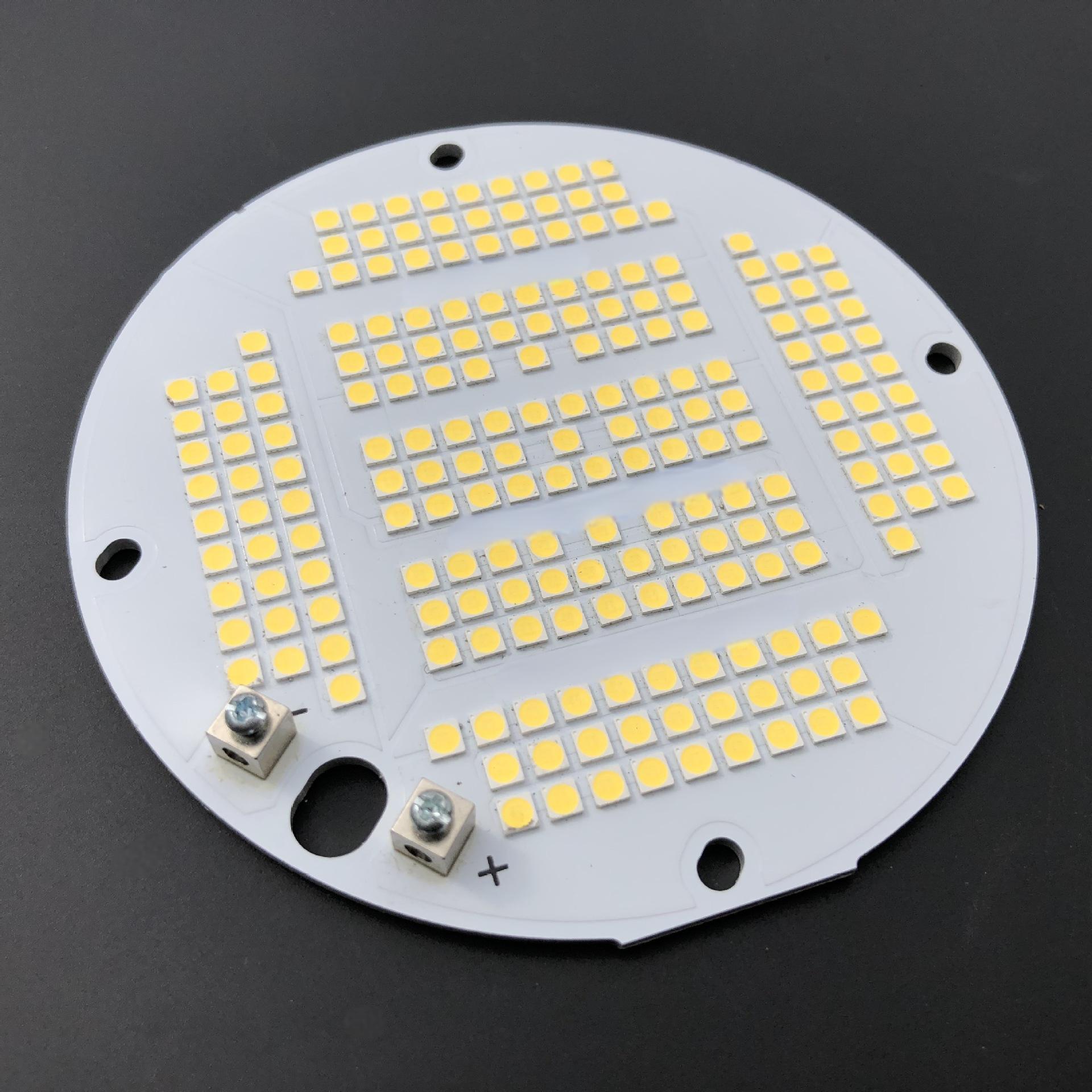
What Should Buyers Ask an Aluminum PCB Manufacturer?

Buyers should ask questions that confirm whether the supplier can control the actual board design and production process. Ask the supplier to review the actual aluminum PCB design.

A practical checklist includes:

  • What is your maximum board length?
  • What is your maximum panel size?
  • What aluminum thicknesses are available?
  • What copper weights can you produce?
  • What dielectric options do you offer?
  • What thermal conductivity options are available?
  • Can you provide thermal resistance data?
  • What breakdown voltage can the dielectric support?
  • What surface finishes are available?
  • What flatness can you control?
  • What IPC class can you support?
  • Do you use AOI?
  • How is electrical testing performed?
  • How are long boards dimensionally inspected?
  • What are the prototype and production lead times?
  • What is the MOQ?
  • Are tooling or NRE charges required?
  • Can you provide PCB assembly?
  • How is lot traceability managed?
  • What quality certifications do you hold?

For long narrow boards, buyers should also ask how the supplier handles the PCB during routing, inspection, storage, and packaging.

These steps have a direct impact on final flatness and mechanical condition.

What Files Should You Send for an Aluminum PCB Quote?

For an accurate aluminum PCB quotation, send enough information for the manufacturer to review dimensions, materials, tolerances, and production requirements.

For bare aluminum PCB projects:

  • Gerber files
  • Fabrication drawing
  • Board dimensions
  • Board thickness
  • Copper weight
  • Aluminum specification
  • Dielectric requirement
  • Thermal conductivity
  • Surface finish
  • Quantity
  • Annual demand, if available
  • Flatness requirement
  • Critical tolerances
  • Electrical test requirements

For PCB assembly projects:

  • BOM
  • Pick-and-place file
  • Assembly drawing
  • Gerber files
  • LED bin requirements
  • Approved component manufacturers
  • Substitution rules
  • Test requirements
  • Prototype quantity
  • Production quantity
  • Forecast, if available

For LED lighting projects, LED bin requirements should be clearly defined when color temperature, brightness, or forward-voltage matching is important.

FAQ About Long Aluminum PCBs

Can a long aluminum PCB replace a flexible LED strip? Only where the installation accepts a rigid board. A conventional aluminum PCB cannot follow curves like a flexible strip, so the mechanical layout and mounting method may need to change.

Is white solder mask an electrical insulation layer? No. In the basic metal-core stackup, the specified dielectric isolates the copper circuit from the aluminum base. White solder mask covers the circuit surface and must not be treated as a replacement for that insulation.

Can LEDs and their driver use the same aluminum board? They can share a board if routing, insulation, thermal conditions and assembly access permit. A separate FR-4 driver board may be more practical when the driver requires more complex routing.

Does increasing aluminum thickness always solve overheating? No. It can change heat spreading and stiffness, but it does not remove resistance in the dielectric or a poor board-to-heatsink interface. Check the complete thermal path before changing thickness.

Can a long board be divided into shorter modules? Yes, if the optical and electrical design allows it. The trade-off is easier handling against additional interconnections, mechanical joints and possible gaps in the light pattern.

Why Choose EBest Circuit for Long Aluminum PCB and PCBA Projects?

EBest Circuit combines aluminum PCB fabrication, component sourcing, and PCB assembly, allowing the bare board, LEDs, BOM, assembly process, and inspection requirements to be reviewed as one project.

For long and narrow LED boards, our engineering review can cover:

  • Board length, width, and thickness
  • Aluminum and dielectric selection
  • Copper weight and circuit layout
  • Flatness and dimensional requirements
  • Panelization and routing
  • LED bin and BOM control
  • SMT process requirements
  • AOI and electrical testing
  • PCBA inspection and functional testing
  • Packaging for long boards

We treat long-board requirements separately from standard MCPCB production because equipment size, handling, flatness, and dimensional control can become more critical as board length increases.

If your project involves a long aluminum PCB, LED MCPCB, FR4 control board, or complete PCB assembly, send your Gerber files, BOM, drawings, quantities, and manufacturing requirements to sales@bestpcbs.com. If assembly is required, include the BOM, pick-and-place file, and test requirements as well.

Our engineering team can review manufacturability, thermal requirements, assembly conditions, and production planning before quotation.

You may also like

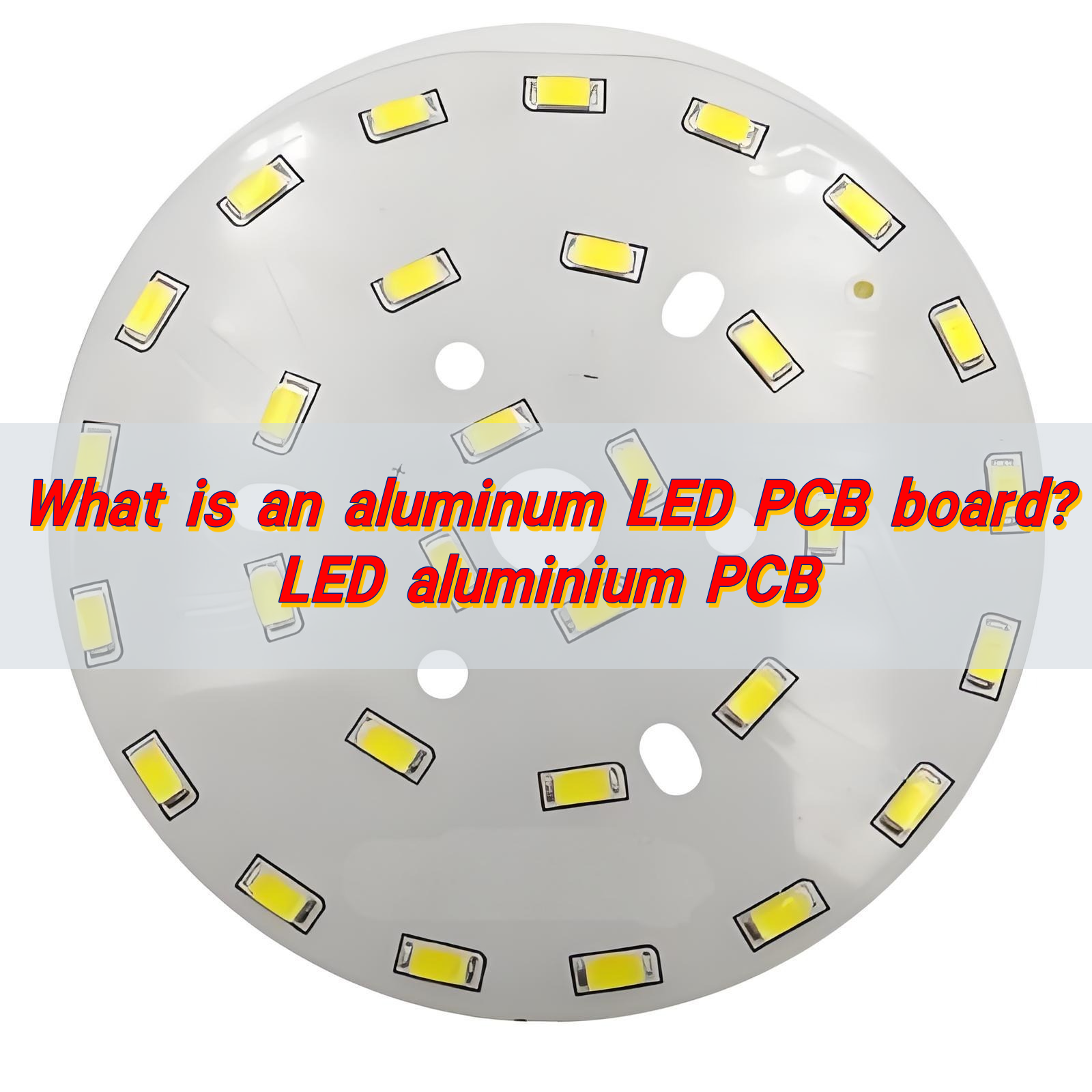
What is an aluminium LED PCB board? LED aluminium PCB
Friday, August 8th, 2025

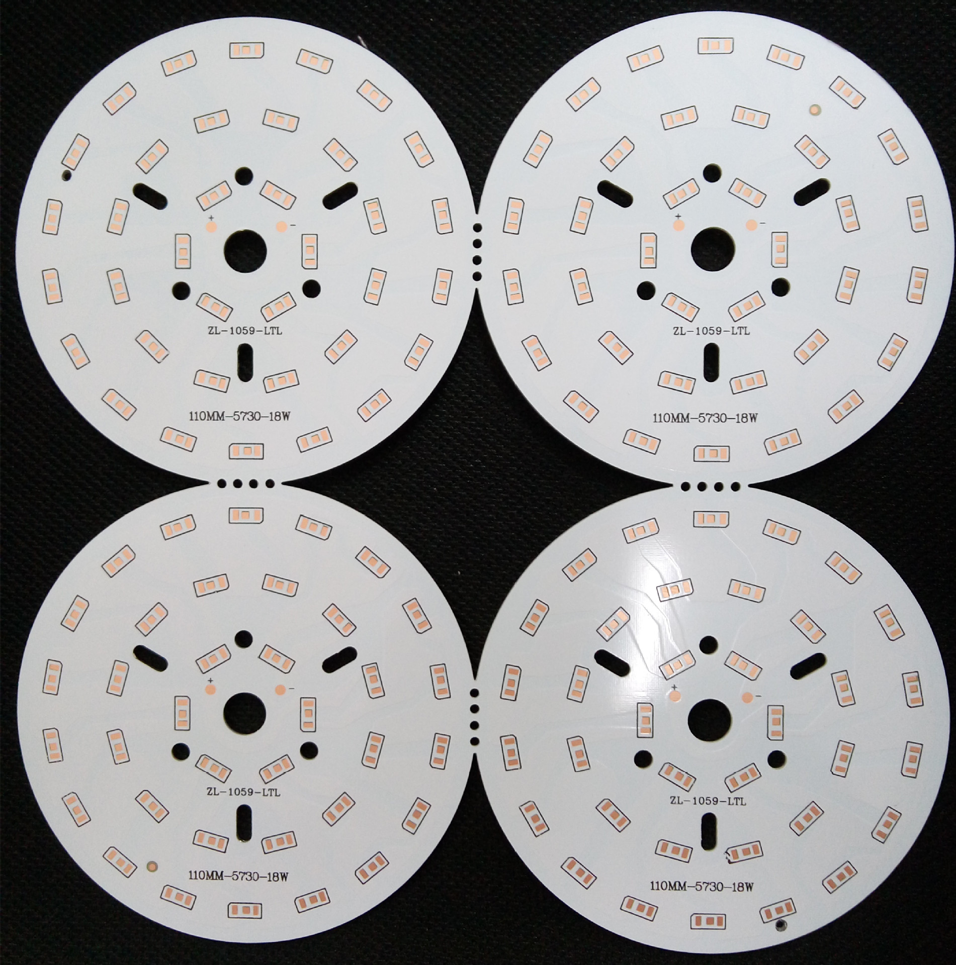
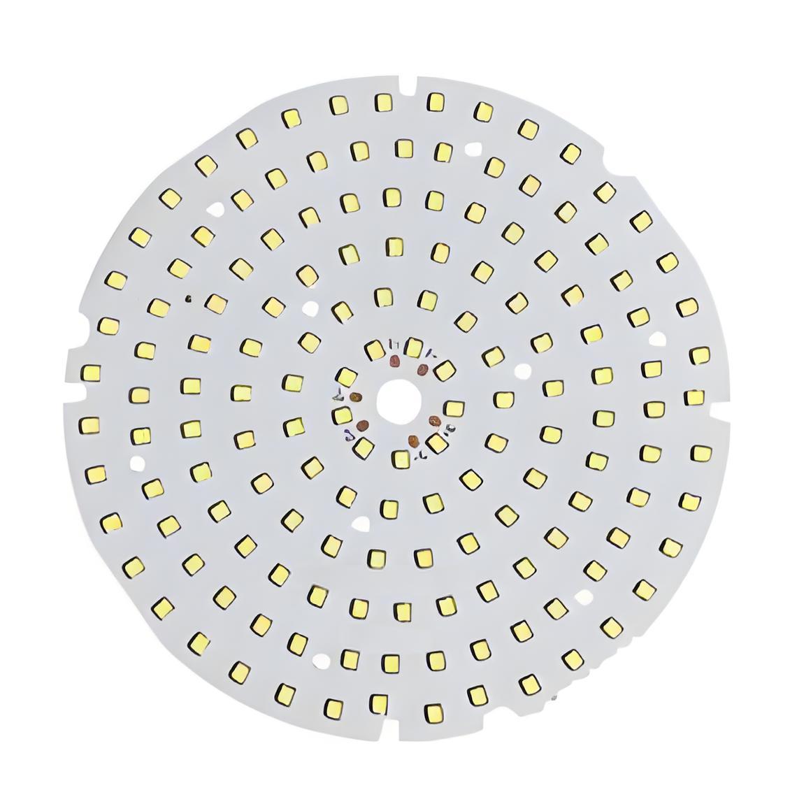
An aluminium LED PCB board is a circuit board with an aluminum base that quickly removes heat from LED components. This keeps the lights cooler, brighter, and longer-lasting. Known for its durability and efficiency, it’s widely used in LED lighting for homes, cars, and industrial devices.

What is an aluminum LED PCB board? LED aluminium PCB

What is an LED aluminium PCB?

An aluminium LED PCB board is a printed circuit board that uses aluminium as the base material. This layer replaces the traditional fiberglass or epoxy base you’ll find in standard PCBs. The board usually consists of three layers: a copper circuit layer, an insulating layer, and the aluminium base.

Why aluminium? Because it dissipates heat much better than other materials. LEDs generate a significant amount of heat, and if it’s not managed well, performance and lifespan suffer. This is where aluminium boards shine.

You might also hear terms like aluminum pcb board, led aluminum plate pcb board, or aluminium led pcb circuit board. They all refer to the same thing.

Why use aluminium PCB board for LED?

LEDs are efficient but sensitive to heat. A high temperature not only dims the brightness but also reduces the LED’s lifespan. That’s why aluminium is the material of choice for LED PCBs.

Here are the reasons why the market chooses aluminum LED PCB boards:

  • Superior heat dissipation: Keeps the LED cool.
  • Stable performance: Even after long hours of operation.
  • Longer lifespan: Your LEDs will last much longer.
  • Lightweight: Ideal for slim lighting devices.
  • Cost-effective: Fewer cooling components are needed.
What is an aluminum LED PCB board? LED aluminium PCB

What are the advantages of aluminium LED PCB?

  • 1. Thermal conductivityThe main benefit is exceptional heat transfer. It quickly pulls heat away from LEDs, helping them work efficiently and safely.
  • 2. DurabilityAluminium is tough. It can handle mechanical stress better than fiberglass boards.
  • 3. Lightweight structureDespite being metal, aluminium is light.
  • 4. Lower energy consumptionCooler operation means LEDs run at optimal performance, using less energy.
  • 5. Eco-friendlyAluminium is recyclable. That makes LED aluminium PCBs a better choice for sustainable manufacturing.
  • 6. High reliabilityThe performance remains stable, even in harsh conditions.

How to design a aluminium pcb circuit board?

Designing an aluminum pcb design takes careful planning. Here are the essential steps:

  • 1. Choose the right stack-upA basic aluminium PCB has a metal base, a dielectric layer, and a copper circuit.
  • 2. Heat analysisKnow where heat will concentrate. Plan the board so thermal paths lead to the aluminium base efficiently.
  • 3. Layout for efficiencyPlace high-heat components away from each other. Spread them out to prevent hotspots.
  • 4. Use thermal viasThey help transfer heat from the top layer to the aluminium base.
  • 5. Pick the correct thicknessA thicker aluminium base offers better heat dissipation but adds weight.
  • 6. Surface finish mattersGo for a finish that resists corrosion and ensures strong soldering.

Aluminium LED PCB vs standard PCB: What’s better?

Let’s compare a standard FR4 PCB with an aluminium led pcb board:

FeatureStandard PCBAluminium LED PCB
Heat DissipationPoorExcellent
LifespanShorterLonger
DurabilityModerateHigh
WeightLightLight
CostLower upfrontSaves on cooling costs
ReliabilityLowerVery high
What is an aluminum LED PCB board? LED aluminium PCB

For high-power applications like LED lighting, the aluminium PCB is clearly the better choice.

What affects aluminium board price for LEDs?

You may be wondering what impacts the aluminium board price or aluminum board price? Several factors determine the cost:

  • Board thickness: Thicker boards cost more.
  • Copper layer weight: Heavier copper increases durability—and cost.
  • Dielectric material: High-grade insulation adds to the price.
  • Board size and shape: Custom shapes are more expensive.
  • Order quantity: Bulk orders typically get better pricing.
  • Surface finish: Extra coatings like ENIG or OSP raise the cost.
  • Lead time: Faster delivery can add urgency charges.

Applications of aluminium LED PCB

These boards are found in a wide range of lighting applications. Here’s where aluminium pcb board for LED really shines:

What is an aluminum LED PCB board? LED aluminium PCB
  • Home lighting: LED bulbs, ceiling lights, and decorative strips.
  • Street lights: Long hours and extreme temperatures demand aluminium PCBs.
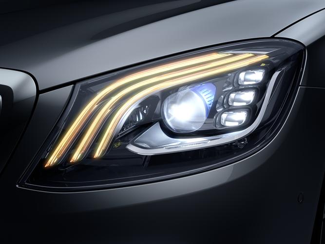
  • Automotive lighting: Headlights and interior LED systems.
  • Backlighting: TVs, monitors, and advertising displays.
  • Medical lighting: Surgical and diagnostic tools need precision and reliability.
  • Industrial lighting: High-bay and warehouse lights.
  • Consumer electronics: Flashlights, phone lights, and wearable devices.

Conclusion:

The aluminium LED PCB board is ability to handle heat, maintain performance, and last longer gives it a huge edge over traditional PCBs. With rising demands for energy-saving and durable solutions, switching to aluminium pcb board for LED is the smart choice.

At EBest Circuit (Best Technology), we specialize in premium-quality aluminium LED PCB boards tailored to your needs. From design to full production, we offer dependable, cost-effective solutions with a quick turnaround.

Get in touch today: sales@bestpcbs.com

You may also like

What is an aluminium PCB board? Aluminum PCB Design
Tuesday, August 5th, 2025

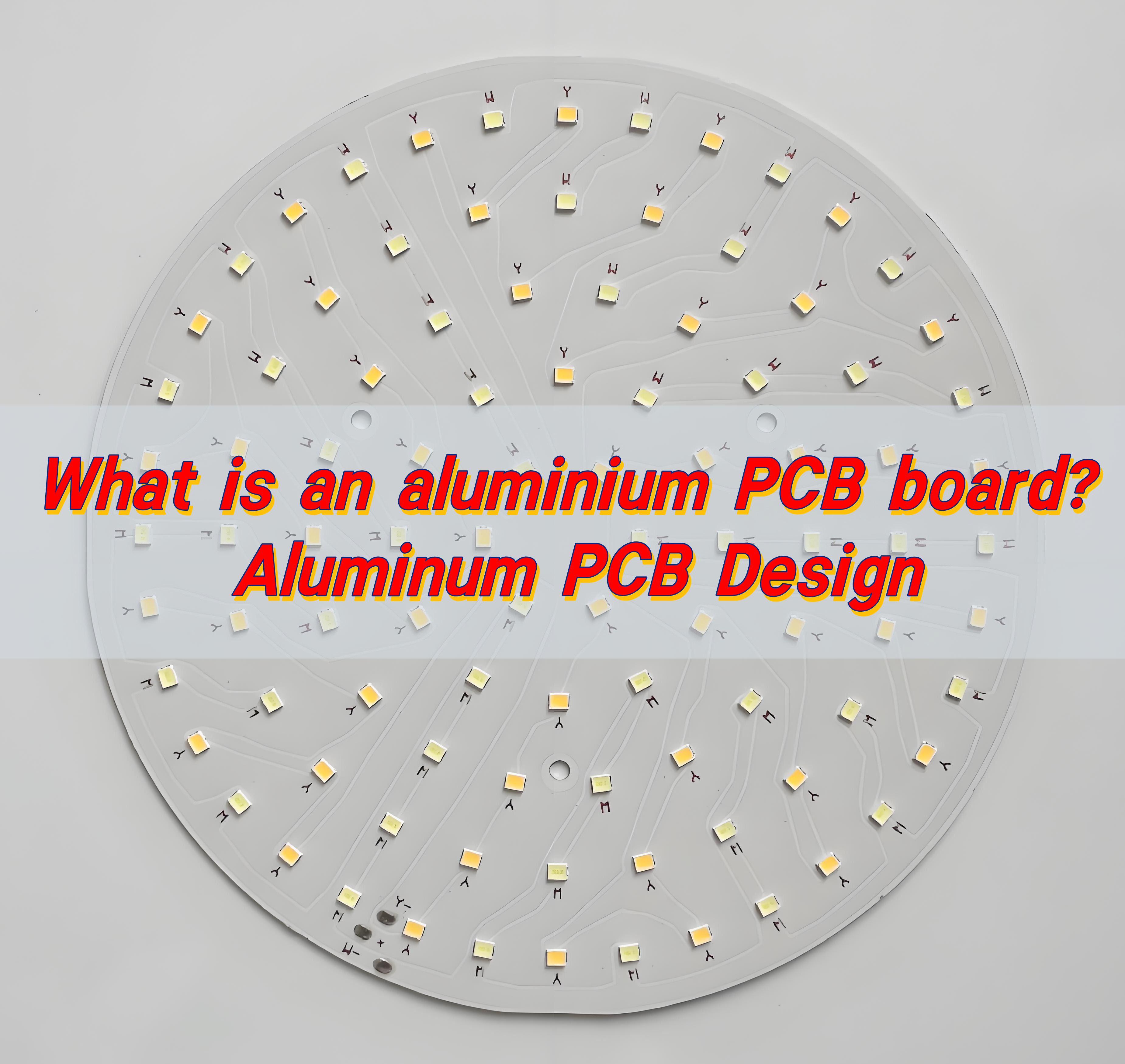
Aluminium PCB boards are metal-based printed circuit boards with an aluminum alloy substrate. Their thermal conductivity is dozens of times higher than that of traditional FR-4, allowing them to quickly dissipate heat from chips and prevent failures caused by hot spots. Combined with highly reflective white oil and a thin insulating layer, they serve as both a circuit and a heat sink, making them widely used in LED lamps, power modules, and automotive electronics.

What is an aluminium PCB board? Aluminum PCB Design

How to make aluminium PCB board?

Making an aluminium PCB board involves precision and the right materials. It starts with choosing a quality aluminium substrate. It’s then coated with an insulating dielectric layer, which isolates the conductive copper from the metal.

Next comes copper lamination. A thin sheet of copper is pressed onto the dielectric surface. This copper layer will form the circuit paths. Once laminated, the board is cleaned and coated with a photoresist. Ultraviolet (UV) light exposure follows, using a circuit design mask to harden certain parts of the photoresist.

Unexposed areas are washed away, revealing the pattern. The exposed copper is then etched off, leaving behind the circuit layout. After this, any remaining photoresist is stripped. Now the board is cleaned and goes through a surface finish process, such as HASL or ENIG, depending on the end-use.

Finally, the board is cut into shape and tested for functionality. Every step is crucial for ensuring electrical performance and heat resistance.

How does the aluminium PCB manufacturing process work?

The aluminium PCB manufacturing process includes several refined steps to deliver a high-quality board. Here is a simplified overview:

  • Material preparation: Choose an aluminium base, usually with a thickness of 0.8mm to 3.0mm. Apply a thermal insulation layer and copper foil.
  • Lamination: Bond the dielectric and copper layers tightly to the aluminium. Heat and pressure ensure this bond holds firm.
  • Imaging: Apply a photoresist film and expose the board under UV light. The light hardens the areas forming the copper traces.
  • Etching: Remove unwanted copper using chemical solutions. Only the protected areas from imaging remain.
  • Drilling and Plating: Drill precise holes for component leads or vias. Plate these holes if needed.
  • Solder Mask and Surface Finish: Apply a protective solder mask to non-conductive areas. Add a surface finish to enhance solderability and corrosion resistance.
  • Testing: Perform electrical tests to check for shorts, open circuits, and reliability.
  • Profiling: Cut the board to the desired size and shape.

These steps are controlled tightly. That’s why working with an experienced aluminium PCB manufacturer is critical.

How to design an efficient aluminum PCB?

Designing an effective aluminium PCB starts with understanding its strengths. Heat management is the top reason to use aluminium. Start by placing high-power components closer to the metal core. This reduces thermal buildup.

Keep trace lengths short and direct. This minimizes resistance and power loss. Use wider traces for higher current paths. Layer stack-up also matters. A single-layer design is often enough for LED and power circuits. For more complex boards, consider a multilayer design.

Thermal vias can help in spreading heat, especially in multilayer boards. Select the right thickness for your dielectric layer to ensure proper insulation and heat flow.

What is an aluminium PCB board? Aluminum PCB Design

When choosing the surface finish, think about the end application. ENIG works well for fine-pitch components. HASL is good for general use.

Excellent aluminum PCB design balances electrical, mechanical, and thermal performance. Choose BEST Technology, you will get the best aluminum PCB design

What are the layers of aluminum PCB?

Aluminium PCB boards generally have three layers:

  • Aluminium Base Layer: This is the mechanical support and heat conductor. It’s usually made of alloy 5052 or 6061 for strength and heat resistance.
  • Dielectric Layer: Placed between the base and copper foil. This insulation layer resists heat and electrically isolates the copper traces. Thickness varies from 50”m to 200”m.
  • Copper Layer: This is the conductive layer where the circuit forms. Thickness can range from 1oz to 3oz depending on current requirements.

Some designs include additional layers:

  • Solder Mask: Applied over the copper to prevent oxidation and short circuits.
  • Silkscreen: For labeling component placements and orientation.

These layers combine to offer durability, high thermal conductivity, and efficient current flow in one compact board.

What is the highest temperature aluminum PCB can withstand?

Aluminium PCBs are built to handle high heat. Their metal base and insulating layer offer much better thermal management than standard FR4 boards. Depending on the material used, aluminium PCBs can endure temperatures between 120°C to 150°C continuously.

For short durations or pulse heating, they can handle spikes up to 250°C. Some high-grade aluminium PCBs, with advanced dielectric materials, may go even higher.

This heat resistance makes them ideal for LED lighting, automotive controls, and power converters. Proper design and material selection can ensure your board works reliably in high-heat environments.

Can aluminum PCB support high frequency signals?

Yes, aluminium PCB boards can support high frequency signals. But it depends on the quality of the dielectric layer. A low-loss dielectric material ensures signal stability.

In high-frequency applications, such as communication devices and radar systems, signal integrity is crucial. Aluminium PCBs with high-performance dielectric can deliver clear, uninterrupted signals.

Design also plays a role. Keep signal paths short and separate analog from digital traces. Ground planes and impedance control improve performance even more.

What is an aluminium PCB board? Aluminum PCB Design

Though aluminium PCBs aren’t the first choice for all RF applications, they work well in many mid-frequency designs.

How strong is FR4 compared to aluminum?

FR4 is the standard fiberglass material used in many PCBs. It’s lightweight, low-cost, and electrically reliable. But when it comes to strength and heat resistance, aluminium is superior.

Aluminium offers better mechanical support. It doesn’t warp under heat like FR4. It also dissipates heat much faster, which is vital in LED or power circuits.

FR4 works well for multi-layer signal processing boards. But for durability, thermal control, and stability, aluminium PCBs outperform FR4 in harsh conditions.

So, if your project demands strength and heat resistance, aluminium PCB is the better choice.

How does aluminum PCB compare to rigid flex and HDI PCB?

Aluminium PCBs, rigid flex PCBs, and HDI PCBs each serve different needs.

  • Aluminium PCB: Best for heat-intensive applications. Offers strong thermal management and mechanical strength.
What is an aluminium PCB board? Aluminum PCB Design
  • Rigid Flex PCB: Combines flexibility and rigidity. Perfect for compact devices with moving parts like cameras or foldable screens.
  • HDI PCB: Designed for high-density circuits with microvias. Used in smartphones, tablets, and miniaturized electronics.

If your design demands heat dissipation and durability, aluminium wins. If space-saving and flexibility are key, go with rigid flex. For high-speed, high-density circuits, HDI is the way to go.

Conclusion:

Aluminium PCB boards are powerful and reliable. In many cases, they outperform traditional solutions in terms of heat dissipation and mechanical strength. Whether you’re working on LED lighting, power electronics, or high-frequency devices, Aluminium PCB boards provide a solid foundation.

Choose a professional partner to get the best results. At EBest Circuit (Best Technology), we specialize in high-quality aluminium PCB boards with custom design support and fast delivery.

Reach out to us today at sales@bestpcbs.com

You may also like

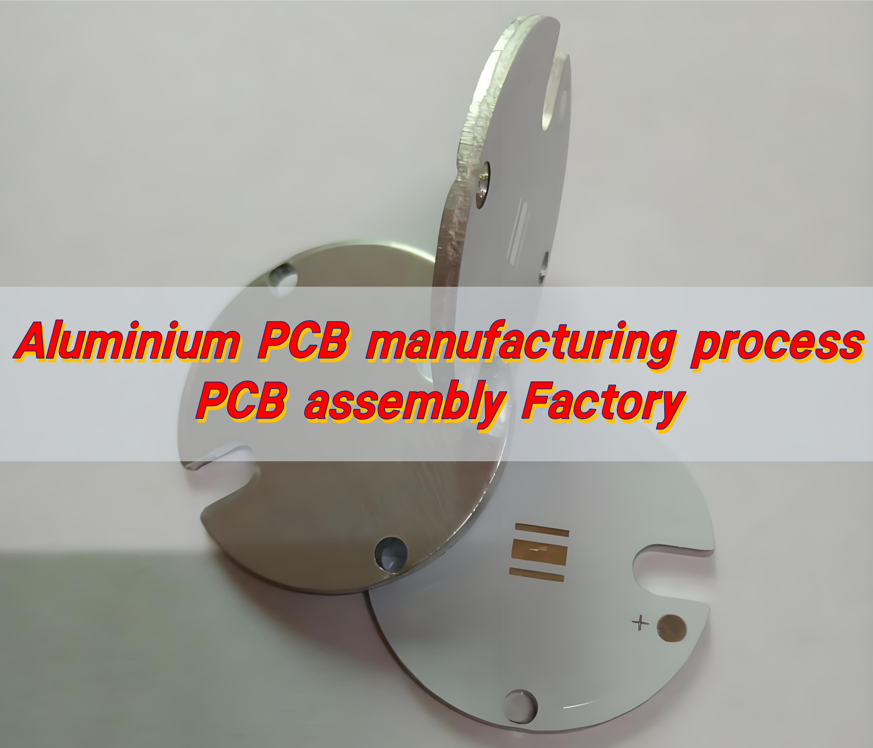
Aluminium PCB manufacturing process, PCB assembly factory
Friday, August 1st, 2025

As a professional aluminum PCB manufacturer, EBest Circuit (Best Technology) delivers reliable, cost-effective solutions with a complete in-house aluminium PCB manufacturing process—from raw material sourcing to final assembly.

How is aluminium PCB made?

Unlike standard FR4 boards, aluminium boards require special materials, customized layering, and high-precision etching to perform reliably under high temperatures.

It begins with a base of aluminium, selected for its thermal conductivity and strength. This base acts as the backbone of the entire structure. Over this, a dielectric layer is added—a thermally conductive yet electrically insulating material. This layer allows heat to pass through to the metal core without shorting the circuit.

Next comes the copper foil. This conductive layer is laminated onto the dielectric using heat and pressure. Once bonded, the copper is patterned using photolithography. Then, etching forms the conductive tracks that carry current across the board.

Finally, the surface is coated with a protective solder mask. The board is drilled, tested, and cut into its final shape, ready for assembly. Every step is controlled to ensure high precision and reliability.

What are the raw materials for aluminum manufacturing?

For aluminium PCBs. The base material is an aluminium alloy, often 5052 or 6061, known for corrosion resistance and good mechanical performance. These alloys are lightweight yet robust, ideal for handling mechanical stress and thermal loads.

Next is the dielectric layer. Typically made of epoxy resin or a ceramic-filled polymer, this layer must be thermally efficient. The goal is to transfer heat quickly without compromising electrical insulation.

The conductive layer is pure copper, usually between 1oz and 3oz thick. This copper sheet is what gets etched to form the traces. To finish, a solder mask is applied to protect the copper and prevent short circuits.

Each material plays a crucial role. Choosing the right combination impacts performance, durability, and cost. That’s why experienced manufacturers like EBest Circuit (Best Technology) take material quality and testing very seriously.

What are the layers of aluminum PCB?

Unlike traditional PCBs, these boards typically have three core layers:

  • Copper Layer: It’s where all the routing happens. The thickness varies based on current load, usually between 35ÎŒm and 105ÎŒm.
  • Dielectric Layer: It insulates the circuit while transferring heat to the metal base. Its thickness affects thermal resistance.
  • Aluminium Base Layer: This bottom layer supports the entire board. It also acts as a heat sink, dissipating excess energy and maintaining stable temperatures.

What are the manufacturing processes for Aluminium?

The aluminium PCB manufacturing process differs slightly from FR4, due to the metal base and heat-sensitive applications.

  • Material Preparation: Aluminium base sheets are cleaned and coated with the dielectric layer.
  • Copper Lamination: A copper foil is bonded using thermal pressure.
  • Image Transfer: Photolithographic techniques are used to apply the circuit pattern.
  • Etching: Unwanted copper is removed, leaving the circuit traces.
  • Drilling: Holes are drilled for vias and mounting points.
  • Plating: If needed, through-holes are plated for multi-layer connectivity.
  • Solder Mask Application: A protective coating is applied to prevent oxidation.
  • Silkscreen Printing: Labels, logos, and identifiers are printed.
  • Surface Finish: ENIG, HASL, or OSP finishes are applied based on customer needs.
  • Final Testing: Each board is electrically tested for continuity and shorts.
  • Routing and Packaging: Boards are cut, inspected, and packed for delivery.

Every step must meet tight tolerances. Even minor defects can affect performance, especially in LED, automotive, and power systems.

What are the pros and cons of aluminum PCB?

Aluminium PCBs have their strengths—and a few limitations.

Pros:

  • Superior Heat Dissipation: Aluminium spreads heat fast. This reduces hotspots and extends component life.
  • High Mechanical Strength: These boards are robust, reducing the risk of cracks and warping.
  • Lightweight Yet Durable: Aluminium provides rigidity without the weight of steel or ceramic.
  • Cost-Effective: Compared to ceramic substrates, aluminium PCBs are more affordable for high-performance needs.
  • Eco-Friendly: Aluminium is recyclable, making it a greener choice.

Cons:

  • Limited Flexibility: Aluminium is rigid. It’s not suitable for flexible PCB applications.
  • Single-Sided Complexity: Most aluminium PCBs are single-layered. Multi-layer designs are possible but more complex and costly.
  • Processing Requirements: Special tools are needed for drilling and etching, raising initial setup costs.

Still, the benefits far outweigh the downsides in most high-power applications. That’s why aluminium boards dominate industries like LED, power electronics, and automotive lighting.

How thick is aluminum PCB?

Thickness matters. It affects strength, heat transfer, and overall reliability.

For aluminium PCBs, the metal base typically ranges from 0.8mm to 3.2mm. The most common thickness is 1.6mm, offering a good balance between strength and heat dissipation. Some high-power applications may use up to 5mm for extra thermal control.

Thickness also depends on the product’s end use. For compact devices like LED bulbs, thinner substrates are preferred. For industrial use, thicker bases ensure long-term performance under heavy loads.

What is the thermal resistance of aluminum PCB?

Thermal resistance is crucial. It determines the heat dissipation performance of the PCB board. The lower the thermal resistance, the better the heat transfer effect, which is one of the advantages of aluminum PCB boards.

A typical aluminium PCB has a thermal resistance between 0.3°C/W and 1.0°C/W. The exact value depends on the dielectric material and its thickness.

The dielectric is designed to transfer heat quickly from the copper layer to the metal base. This lowers component temperature, improves performance, and extends lifespan.

How thick is the dielectric layer of aluminum PCB?

The dielectric layer not only ensures the passage of heat, but also acts as an insulator. The thickness of the dielectric layer directly affects the insulation performance and thermal resistance.

Most dielectric layers are between 50ÎŒm and 150ÎŒm thick. Thinner layers offer better heat transfer but may reduce electrical insulation. Thicker layers improve isolation but limit thermal performance.

Choosing the right thickness is about balance. It depends on voltage requirements, power density, and end-use environment.

How do aluminium PCBs work?

Aluminium PCBs work by balancing three critical needs: electrical conduction, mechanical support, and heat dissipation. They combine a conductive copper layer with a heat-spreading aluminium base, connected by a special dielectric.

When current flows through the copper traces, it generates heat. The dielectric layer moves this heat down to the aluminium base, which then spreads it across the board and out to the environment. This keeps components cool, even under heavy load.

When to use aluminum PCB?

Aluminum PCBs are widely used in applications where heat is an issue. That includes:

  • LED Lighting: Heat control improves brightness, lifespan, and efficiency.
  • Power Supplies: High-current paths stay cool and stable.
  • Automotive Electronics: High vibration resistance is perfect for engine bays and dashboards.
  • Communication Equipment: Enhanced thermal management ensures signal reliability.
  • Industrial Controllers: Strong mechanical support reduces failure under stress.

If your design involves high-power components or tight thermal tolerances, aluminium PCBs are the solution.

Conclusion:

Aluminum substrates have good thermal conductivity, mechanical strength and cost-effectiveness. Whether you’re building LED lights, industrial controls, or automotive systems, aluminium PCBs provide a solid foundation. Their superior heat management protects components, improves efficiency, and extends service life.

If you’re ready to upgrade your design with dependable aluminium PCBs, our experts at EBest Circuit (Best Technology) are here to help. With advanced equipment, experienced engineers, and quick turnaround, we deliver quality you can trust. Contact us now at sales@bestpcbs.com

You may also like