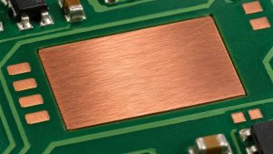
A filled and capped via can still leave a depression or a raised area on a BGA land. Inspect the finished pad surface relative to an agreed datum; inspect fill and cap integrity separately. A feature that passes electrical continuity can still be unsuitable for the intended assembly.
Consider a hypothetical high-density processor board with some BGA pads directly over filled vias. The design owner wants to compare those lands with neighboring pads before the first board is assembled.
Identify the Surface That Will Receive Solder
Measure the solderable land after the specified fabrication and finish steps. A flat surface before final plating or finish is not necessarily the final geometry. Name the inspection stage and identify which pads contain the via.

Compare Three Inspections That Answer Different Questions
No single inspection proves every part of the construction.
| Inspection | Can address | Does not establish alone |
| Surface profile | Dimple, protrusion or height difference | Internal void or cap continuity |
| Cross-section | Fill, cap and barrel structure on the section | Every pad on the panel |
| Electrical test | Connectivity and isolation at test time | Assembly planarity or solder behavior |
Define Flatness Parameters Before Quoting a Limit
The drawing needs an explicit datum, a method and separate decision limits where applicable. Eurocircuits’ via filling overview describes filling and planarization as process steps; it does not establish the limits for this example.
| Field | Report as | Purpose |
| Local depression | µm below a defined reference | Identify the recessed region |
| Local protrusion | µm above that reference | Identify a raised region |
| Pad-to-pad height | µm with the agreed datum | Check relative land elevations |
| Sampling | Pad IDs, panel location and method | Reproduce the result |
Separate a Dimple From Board-Level Bow
A dimple is local to the pad or via region. Board-level shape changes the height over a wider area. A tilted sample can make a profile look sloped; document the leveling and reference before calling the shape a cap defect.
Include a Neighboring Reference Land
Use a reference surface agreed in advance, such as an adjacent unaffected area when that is appropriate for the measurement. Compare like finish and geometry where possible. Avoid selecting the reference after seeing the result simply because it makes the number smaller.
Read a Simple Height Example
If an illustrative surface profile is zero at the agreed reference and reaches −8 µm at the center, the local depression is 8 µm by that definition. If another point reads +5 µm, report that separately as a protrusion. These numbers are teaching inputs, not acceptance limits.
Choose an Inspection Method That Can Resolve the Feature
Ask what the instrument can resolve on the actual pad material and size. The report should name the method, location and how the datum was applied. An ordinary microscope image can show a visible feature but should not be treated as a calibrated height result by itself.

Distinguish a Surface Signature From Its Cause
A recess alone does not prove a particular fill defect or process setting. Check whether the signature follows via geometry, pad type or panel location. Use the fabrication history and a targeted section when necessary to determine whether the fill, planarization or plating requires investigation.
Verify the Cap and the Fill When the Drawing Requires It
If the assembly needs a defined cap and filled structure, specify the agreed checks independently of top surface profile. A smooth-looking land cannot rule out an internal defect. A section also has sampling limits, so identify which land and region it represents.
Inspect a Useful First-Article Sample
Select pads and panel locations that represent the constructions being released. Include via-bearing and comparable non-via lands where relevant. Retain the map so the assembler can connect any later solder finding to the corresponding pad type rather than the panel average.
Carry Surface Data Into Assembly Review
If the first assembly shows a solder anomaly, compare the actual pad, stencil, package and reflow evidence. Do not assume a via caused the issue just because it sits below the land. Use the surface report to guide the investigation, not to replace it.
Release the Land Geometry and Its Evidence Together
State the pad construction, finish, datum, measurement method, sampling and response to exceptions. See the Best Technology via-in-pad guide for the general filled-and-capped construction; this inspection applies to the finished surface.
FAQ
Does filling the via guarantee a flat land?
No. Filling and making a finished pad surface are related but different operations. Check the completed surface under the agreed method, and use the required separate inspection for the fill and cap structure. Do not infer compliance from the word filled on a purchase line.
Can I judge height from the color of a gold pad?
No. Lighting and surface reflectivity can change the appearance without a corresponding height change. Use an appropriate and verified profile measurement when the requirement is in micrometers. A photograph may help locate the feature but does not replace the measured height.
Is there a single dimple limit for all BGAs?
Do not assume one. The accepted value depends on the governing drawing, construction and assembly requirements. Agree on the definition and datum with the responsible teams before fabrication, especially when different suppliers may use different inspection methods or report the result differently.
What if the measurement includes solder mask?
Check whether the datum is supposed to reference the solderable land or a different feature. A mask edge can change a profile and make readings incomparable. The report should show where the scan crossed the surface and how unrelated regions were excluded.
Does X-ray directly measure a pad dimple?
Do not use a general X-ray observation as proof of local surface height. X-ray can support different inspection tasks depending on the equipment and method. For a specified dimple or protrusion, use the agreed surface measurement and correlate any structural findings separately.
Can I average several pads to pass a local limit?
Only if the governing requirement specifically defines such an average. A mean can hide one outlying pad. When the rule is a maximum local deviation, record individual locations and values so the owner can assess the actual worst case before assembly.
Why check both depression and protrusion?
They describe opposite departures from the agreed reference and can affect the assembly differently. A single unsigned number can hide whether the surface was raised or recessed. Keep both directions in the report and compare them with the appropriate requirements for the design.
When should I repeat first-article checks?
Review them when a material, via construction, finish, process route or other relevant variable changes. The appropriate sample depends on the approved control plan. Keep the old and new configuration identifiers together so an inspection result cannot be assigned to the wrong build.
Prepare a BGA Land Review
Send the stackup, via and BGA pad drawing, proposed measurement method and acceptance limits to the Best Technology team.